MULTIPLEX COMMUNICATION
-
GENERAL
-
The Controller Area Network (CAN) is a serial data communication network for real time application. It is a multiplex communication network equipped in a vehicle, and has communication speeds of 500 kbps (HS-CAN) and 250 kbps (MS-CAN), and the ability to detect malfunctions.
-
The HS-CAN consists of the Bus 2, Bus 3, Bus 5, V bus, Sub Bus 15 and local bus.
-
The MS-CAN consists of the Sub Bus 1.
-
The central gateway ECU has a gateway function and is used to transmit data between the Bus 2, Bus 3, Bus 5 and V bus.
-
The main body ECU (multiplex network body ECU) has a gateway function and is used to transmit data between the Bus 2 and Sub Bus 1.
-
The CAN has 2 terminating resistors which are necessary for accurate judgment of communication on the main bus.
-
The communication wire used is a twisted-pair wire. The bus line has a high line (2.5 V to 3.5 V of voltage is applied) and a low line (1.5 V to 2.5 V of voltage is applied).
-
-
SYSTEM DIAGRAM
Figure 1. Bus 5
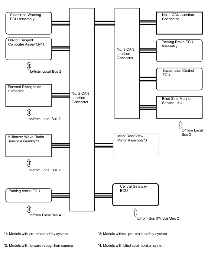
Figure 2. Bus 3 for LHD
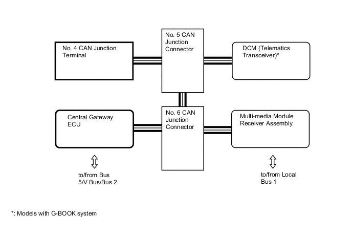
Figure 3. Bus 3 for RHD
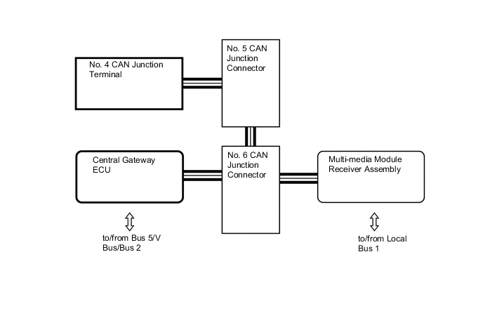
Figure 4. V Bus
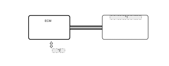
*1 Central Gateway ECU *2 to/from Bus 5/Bus 3/Bus 2 Figure 5. Bus 2 for LHD 1
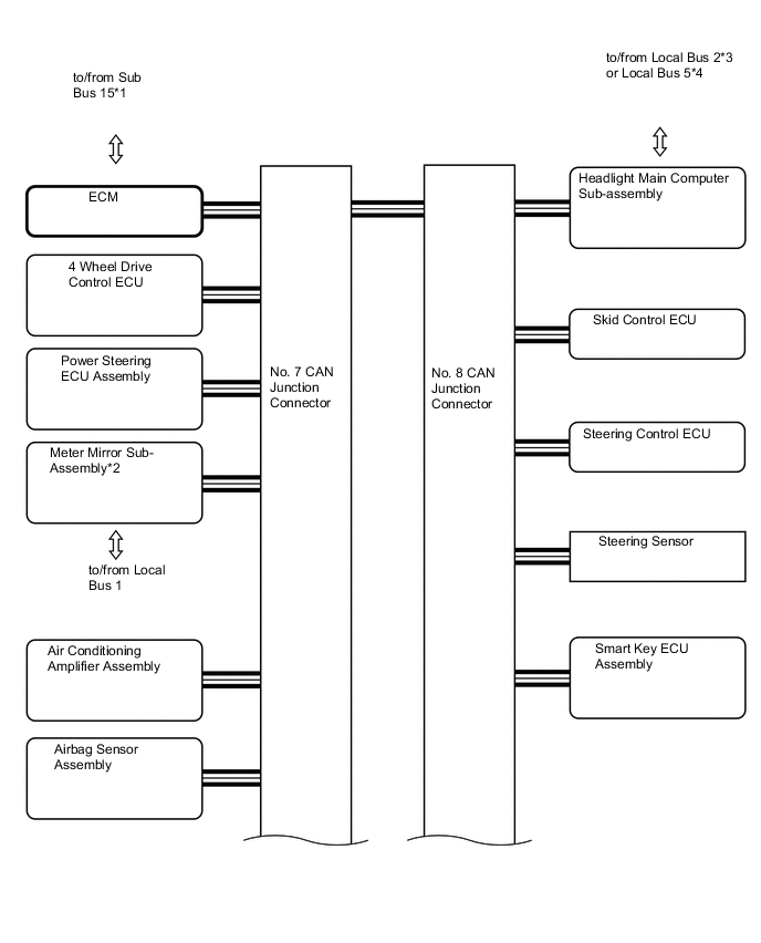
Figure 6. Bus 2 for LHD 2
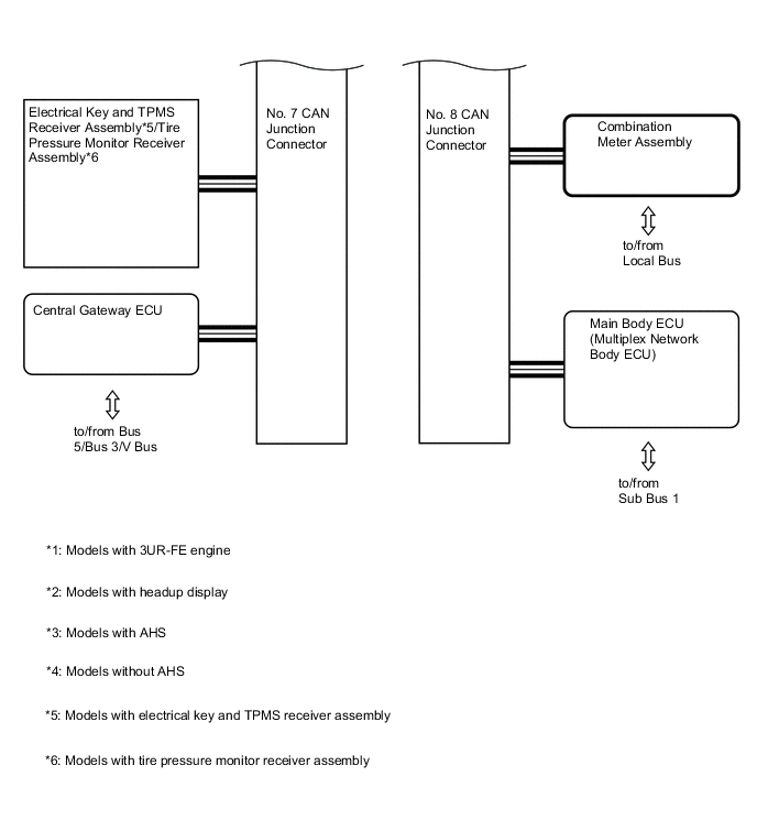
Figure 7. Bus 2 for RHD 1
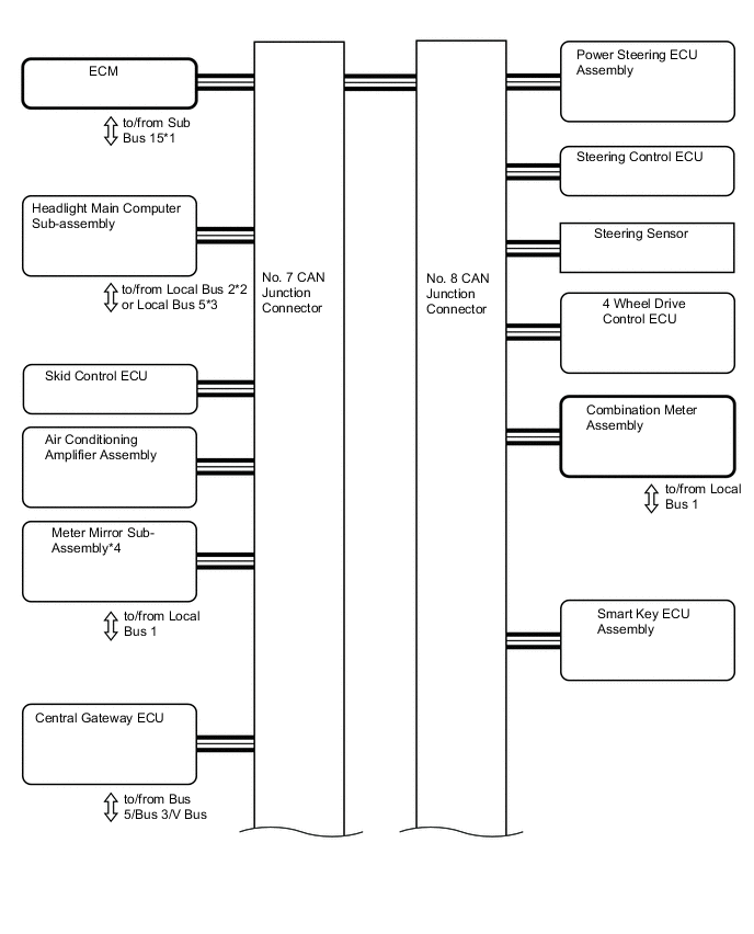
Figure 8. Bus 2 for RHD 2
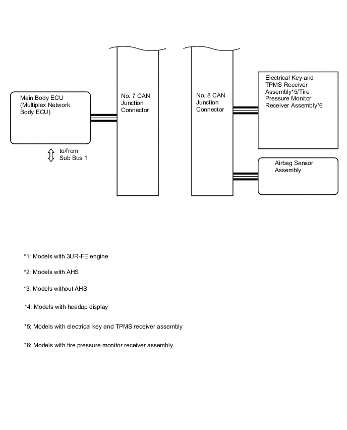
Figure 9. Sub Bus 15(Models with 3UR-FE Engine)
*1 Transmission Control Computer Assembly *2 to/from Bus 2 Figure 10. Sub Bus 1 for LHD
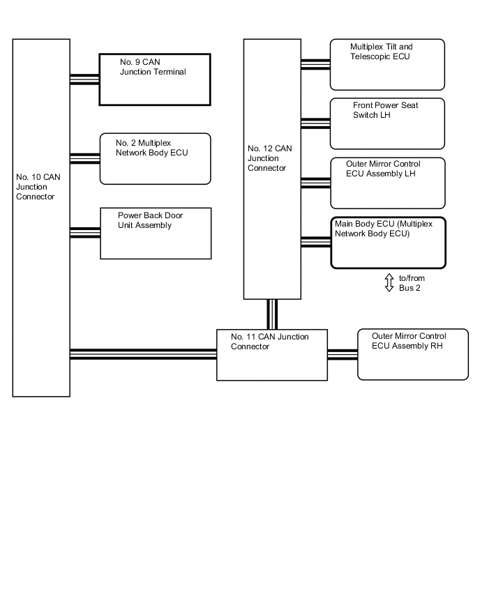
Figure 11. Sub Bus 1 for RHD
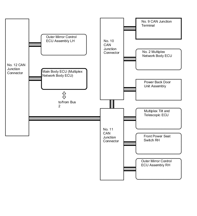
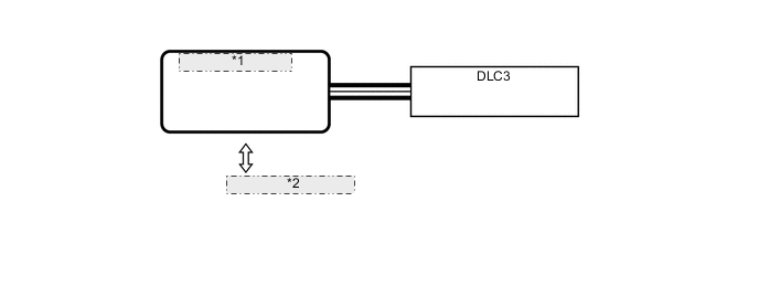
Figure 12. Local Bus 1
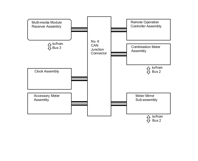
Figure 13. Local Bus 2
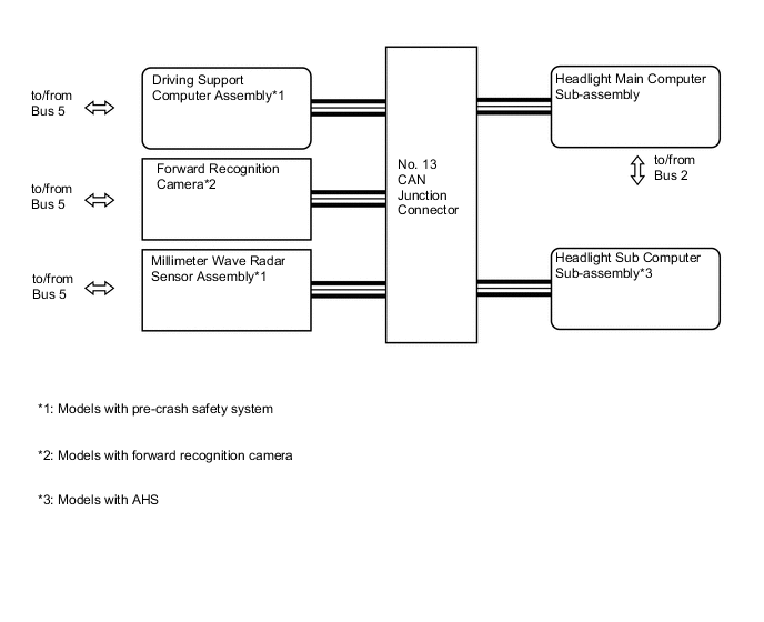
Figure 14. Local Bus 3
Figure 15. Local Bus 4
Figure 16. Local Bus 5 (Models without AHS)
*1 Headlight Main Computer Sub-assembly *2 Headlight Sub Computer Sub-assembly *3 to/from Bus 2 -
LAYOUT OF MAIN COMPONENTS
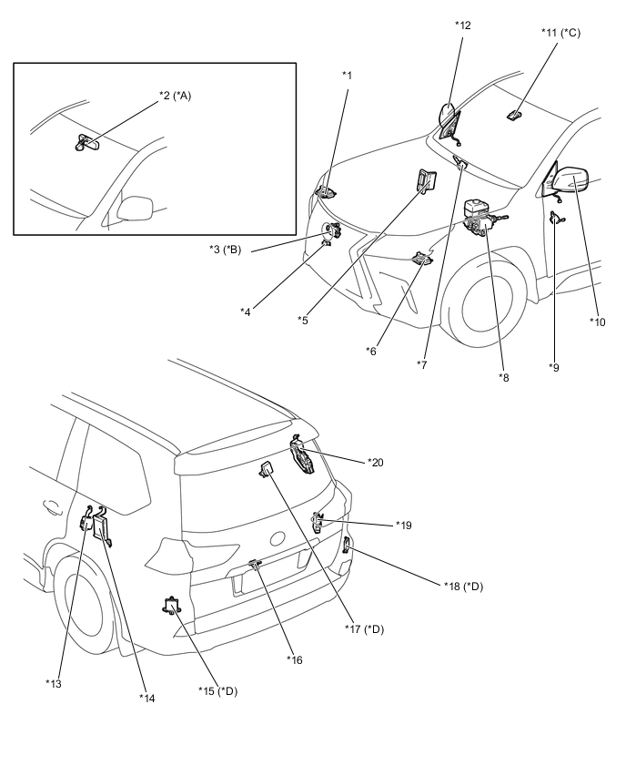
*A Models without Pre-crash Safety System *B Models with Pre-crash Safety System *C Models with Forward Recognition Camera *D Models with Blind Spot Monitor System *E Models with Electrical Key and TPMS Receiver Assembly - *1 Headlight Sub Computer Sub-assembly *2 Inner Rear View Mirror Assembly *3 Millimeter Wave Radar Sensor Assembly *4 Front Television Camera Assembly *5 ECM *6 Headlight Main Computer Sub-assembly *7 Outer Mirror Control ECU Assembly RH *8 Skid Control ECU *9 Outer Mirror Control ECU Assembly LH *10 Outer Rear View Mirror Assembly LH *11 Forward Recognition Camera *12 Outer Rear View Mirror Assembly RH *13 Parking Brake ECU Assembly *14 Suspension Control ECU *15 Blind Spot Monitor Sensor LH *16 Rear View Camera (Television Camera with Dynamic Guide Line Assembly) *17 Electrical Key and TPMS Receiver Assembly *18 Blind Spot Monitor Sensor RH *19 No. 2 Multiplex Network Body ECU *20 Power Back Door Unit Assembly 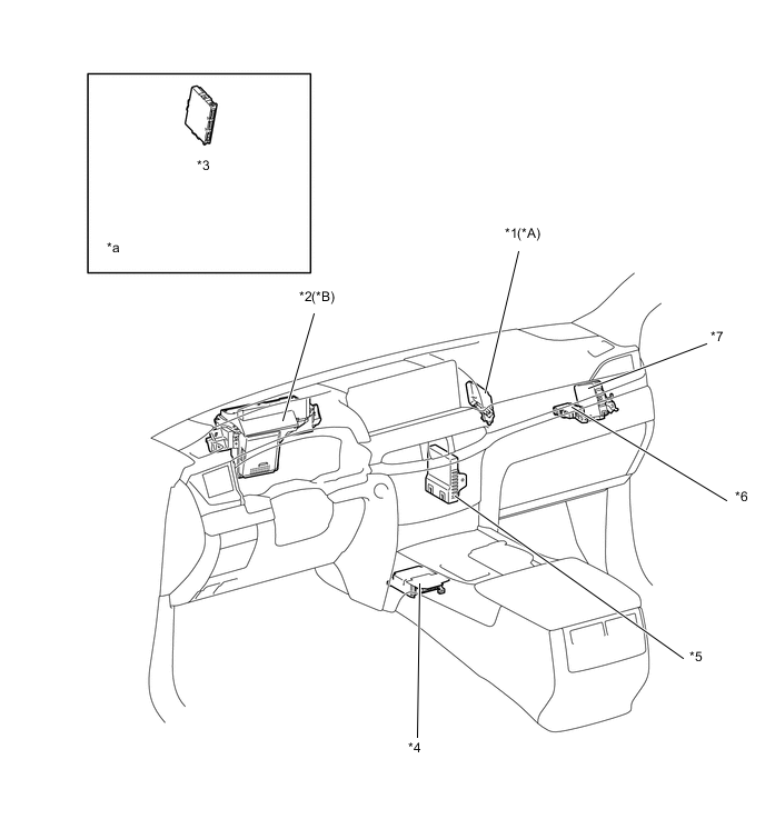
*A Models with Pre-crash Safety System *B Models with Headup Display *1 Driving Support Computer Assembly *2 Meter Mirror Sub-assembly *3 Smart Key ECU Assembly *4 Airbag Sensor Assembly *5 Air Conditioning Amplifier Assembly *6 Central Gateway ECU *7 4 Wheel Drive Control ECU - - *a Refer to the Service Bulletin for the installation position of the part. - - 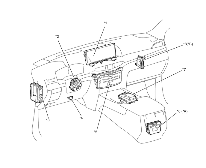
*A Models with G-BOOK System *B Models with 3UR-FE Engine *1 Accessory Meter Assembly *2 Steering Sensor *3 Main Body ECU (Multiplex Network Body ECU) *4 DLC3 *5 Multi-media Module Receiver Assembly *6 DCM (Telematics Transceiver) *7 Remote Operation Controller Assembly *8 Transmission Control Computer Assembly 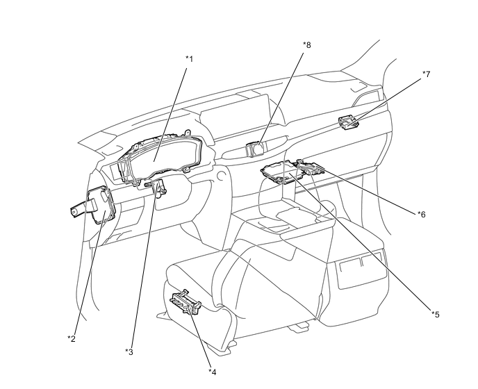
*1 Combination Meter Assembly *2 Steering Control ECU *3 Multiplex Tilt and Telescopic ECU *4 Front Power Seat Switch LH *5 Parking Assist ECU *6 Clearance Warning ECU Assembly *7 Power Steering ECU Assembly *8 Clock Assembly -
DIAGNOSIS
-
If a malfunction occurs on the CAN communication line, the ECU that is connected to the CAN communication line stores the DTC (Diagnostic Trouble Code) in its memory.
-
For details, refer to the Repair Manual
-