BRAKE
-
General
-
The brake control system has the following functions:
Function Outline Multi-terrain Anti-lock Brake System (ABS) The ABS helps prevent the wheels from locking when the brakes are applied firmly or on a slippery surface. In addition to the existing ABS function, the multi-terrain ABS automatically selects the optimum ABS control for the off-road situation such as a dirt road or a sandy road, providing the most suitable brake force for the ground surface. Electronic Brake force Distribution (EBD) The EBD utilizes multi-terrain ABS, realizing the proper brake force distribution between front and rear wheels in accordance with the driving conditions. In addition, during cornering braking, it also controls the brake forces of right and left wheels, helping to maintain the vehicle behavior. Brake Assist The primary purpose of the brake assist is to provide an auxiliary brake force to assist the driver who cannot generate a large brake force during emergency braking, thus helping draw the vehicle's brake performance. Active Traction Control (A-TRC) During rugged off-road driving, this function controls the engine output and the brake fluid pressure that is applied to the slipping wheel, and distributes the drive force that would have been lost through the slippage to the remaining wheels in order to achieve an Limited Slip Differential (LSD) effect. As a result, the vehicle's off-road drivability and ability to free itself from bumping have been increased. Vehicle Skid Control (VSC) The VSC system helps prevent the vehicle from slipping sideways as a result of strong front wheel skid or strong rear wheel skid during cornering. Trailer Sway Control If the tongue load is not properly adjusted while towing a trailer, trailer sway may be caused due to crosswinds, bumpy roads, steering operation, etc. Trailer sway control detects sway and regulates the brake of each wheel and the motive force output in order to suppress trailer sway. Hill-start Assist Control When the vehicle starts off on a steep or a slippery hill, hill-start assist control detects the backward descent of the vehicle and effects 4-wheel hydraulic pressure control to reduce the backward speed of the vehicle. As a result, the vehicle can be started off on a hill more easily. CRAWL (with Turn Assist Function)
-
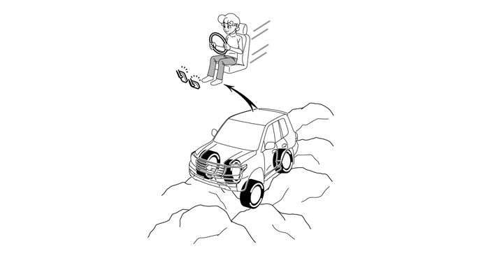
When the vehicle runs on extremely bumpy rough ground or a slippery road, the CRAWL is activated to regulate the engine output and the hydraulic pressure of the 4 wheels, allowing the driver to drive the vehicle at the desired speed and keep that speed with virtually no accelerator or brake pedal operation. As a result, the off-road ground covering performance has been more improved.
-
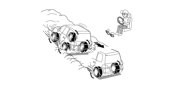
When driving through a tight corner that cannot easily be passed through without cutting the steering wheel in the opposite direction, a control is implemented by using the turn assist function to improve turning performance in response to the driver's steering while constant low speed is maintained by CRAWL control, thus reducing the driver's steering operation.
Tech Tips
When the brake control system is activated, the brake pedal could shudder, which is a normal occurrence of the system in operation and should not be considered as a malfunction.
-
-
-
Multi-terrain Select
-
General
-
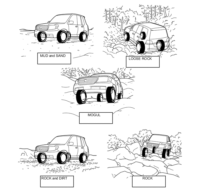
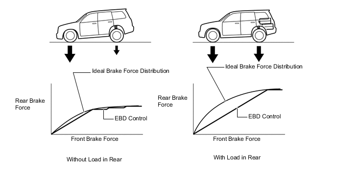
When driving on off-roads of varying surfaces, multi-terrain select starts controlling when a road mode is selected by operating the mode select switch.
-
The following road modes; MUD & SAND, LOOSE ROCK, MOGUL, ROCK & DIRT and ROCK can be selected. The brake control is automatically switched to A-TRC, thus achieving a superior off-road traction.
-
To optimally control the wheel spin and wheel lock in response to the road surfaces, a superior traction is ensured on slippery road surfaces and on uphills with steep inclines.
-
-
Multi-terrain Select Control
-
A-TRC and engine output control are performed in accordance with the road mode selected by the driver.
-
The CRAWL control is activated when the accelerator pedal is released and the multi-terrain select is activated in the AUTO mode when the accelerator pedal is depressed.
-
When the CRAWL control is deactivated, one of the 5 road modes of MUD & SAND, LOOSE ROCK, MOGUL, ROCK & DIRT, and ROCK can be selected with the mode selector switch.
-
The AUTO mode will be selected automatically when the CRAWL control is activated.
-
The multi-terrain select indicator light, slip indicator light, CRAWL indicator light and multi-information display operate to inform the driver of the multi-terrain select operating conditions.
Multi-terrain Select Road Mode Transfer Drive Mode Control A-TRC Control Results Mud and Sand L4 The wheels are allowed to slip more than usual. Outputs a large amount of drive force and suppresses deceleration feeling by assuming that the vehicle is driving on a soft, slippery road surface. Loose Rock L4 The wheels are allowed to slip more than usual. Outputs a large amount of drive force and suppresses deceleration feeling by assuming that the vehicle is driving on slippery or loose-graveled uphill slopes. Mogul L4 The wheels are made to grip more than usual. Suppresses deceleration feeling to achieve smooth driving on hills while improving LSD function by assuming that the vehicle is driving on a highly bumpy road surface. Rock and Dirt L4 The wheels are made to grip more than usual. Gives the wheels grip and improves the LSD function by assuming that the vehicle is driving on a highly bumpy road surface. Rock L4 The wheels are made to grip more than usual. Gives the wheels grip and improves the LSD function by assuming that the vehicle is driving on a highly bumpy road surface. Auto L4 The control is optimized in response to the vehicle speeds set in the CRAWL control. An optimum A-TRC will automatically be selected by further depressing the accelerator pedal to add more traction force while running with the CRAWL control activated. -
Each indicator lights and multi-information display operate as follows:
Indicator Light Condition Multi-terrain Indicator Light CRAWL Indicator Light Slip Indicator Light Multi-terrain Select Operates ○ - - A-TRC Operates ○ - ▲ CRAWL is activated and the accelerator pedal is depressed. ○ ○ ▲ CRAWL is activated and the accelerator pedal is released. ○ ○ ▲ System Malfunctions X - ○ Tech Tips
○: Illuminates
▲: Blinks
X: Turns off
-: Not applicable
Multi-information Display Condition Multi-information Display Multi-terrain Select Operates Displays The Road Mode Being Selected. A-TRC Operates Displays The Road Mode Being Selected. CRAWL is activated and the accelerator pedal is depressed. Multi-terrain Select "AUTO" CRAWL is activated and the accelerator pedal is released. CRAWL Operates System Malfunctions -
-
-
Multi-terrain Operation Condition
-
By selecting the road mode through the mode select switch operation when all of the following conditions are met, the control status will become READY and the multi-terrain select indicator light will turn on. In addition, if all of the following conditions cannot be met, the multi-terrain select indicator light will turn off to finish control.
-
When A-TRC operates in this condition, the slip indicator light will flash.
Multi-terrain Select Operate Condition
-
Transfer drive mode is in L4.
-
The VSC OFF switch is off.
-
The brake control system is normal.
-
-
-
-
Outline of Brake Control Functions
-
Multi-terrain Anti-lock Brake System (ABS)
-
General
-
The conventional ABS regulates the hydraulic brake pressure of all the wheels by monitoring the wheel speeds during braking, and prevents the wheels from locking when braking to ensure the vehicle stability and the steering maneuverability. The newly provided multi-terrain ABS has a function that detects the off-road ground conditions such as sand, mud, or gravel via information such as the engine output, vehicle acceleration rate, and wheel speeds, and then selects the optimum ABS control in accordance with the situation. As a result, the braking feel in off-road driving has been enhanced.
-
-
Effectiveness of Multi-terrain ABS
-
Through the addition of the engine output information to the existing control information, the accuracy of determining the road surface conditions has been more improved. By changing the slip rate in accordance with the road surface, it secures superior braking performance on the off-road surface.
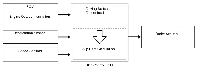
Figure 1. Hydraulic Pressure Control Image of Multi-terrain ABS
-
-
-
Electronic Brake force Distribution (EBD)
-
General
-
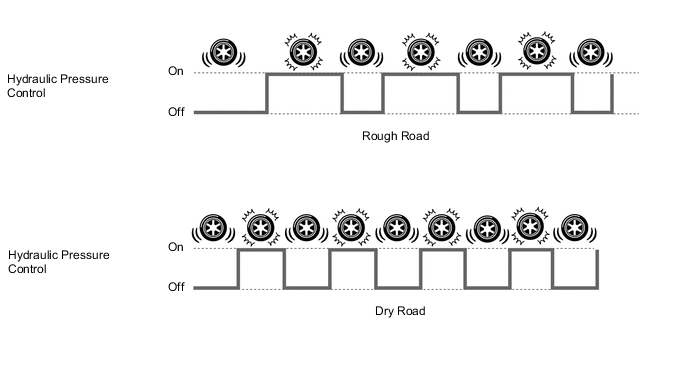
The EBD control utilizes the multi-terrain ABS, realizing the proper brake force distribution between the front and rear wheels in accordance with the driving conditions. In addition, during cornering braking, it also controls the brake forces of the right and left wheels, helping to maintain the vehicle behavior.
-
-
Front/Rear Wheels Brake Force Distribution
-
This function controls the brake force that acts on the rear wheels in accordance with the changes in the vehicle conditions such as load factors or deceleration, in order to ensure excellent braking performance.
Figure 2. EBD Control Concept
-
-
Right/Left Wheels Brake Force Distribution (During Cornering Braking)
-
During cornering braking, this function controls the brake force that acts on the left and right wheels in accordance with the vehicle conditions at that time. This ensures vehicle stability and excellent braking performance.

*1 Control Moment *2 Brake Force
-
-
-
Brake Assist
-
The primary purpose of the brake assist is to provide an auxiliary brake force to assist the driver who cannot generate a large brake force during emergency braking, thus helping draw the vehicle's brake performance.
-
Based on the signals from the master cylinder pressure sensor, the skid control ECU calculates the speed and the amount of the brake pedal application and then determines the intention of the driver to make an emergency braking. If the skid control ECU determines that the driver intends the emergency braking, this function activates the brake actuator to increase the brake fluid pressure, which increases the brake force.
Figure 3. In case that the driver's depressing force is small when applying emergency braking
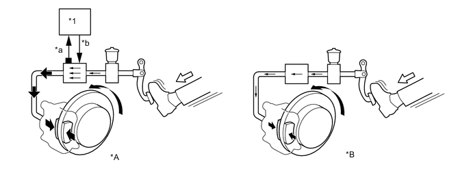
*A Models with Brake Assist *B Models without Brake Assist *1 Skid Control ECU - - *a Master Cylinder Pressure Sensor Signal *b The fluid pressure is increased by the hydraulic brake booster. 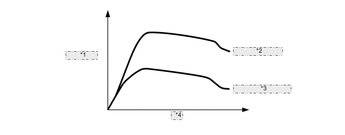
*1 Brake Force *2 With Brake Assist *3 Without Brake Assist *4 Time Tech Tips
There is no difference of the maximum brake performance between the vehicles with and without brake assist.
-
-
Active Traction Control (A-TRC)
-
General
-
If a tire slips while the vehicle is being driven on a snow-covered road or a rough road, the function of the differential gear causes a large amount of drive force to be applied to the tire that is slipping.
-
The A-TRC function helps restrain the slippage by controlling the engine output and brake fluid pressure that is applied to the slipping wheel, and distributes the drive force that would have been lost through the slippage to the remaining wheels in order to achieve an effect that is similar to the Limited Slip Differential (LSD).
-
It independently controls the brake hydraulic pressure to the 4 wheels in accordance with the extent of the slippage at the wheels, as detected by the skid control ECU.
Figure 4. With A-TRC
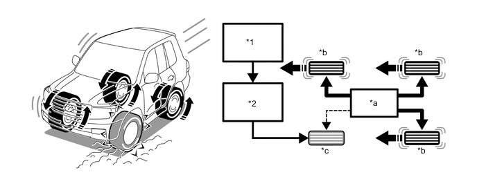
*1 Skid Control ECU *2 Hydraulic Brake Booster *a Driving Force *b Traction *c Braking - - Figure 5. Without A-TRC
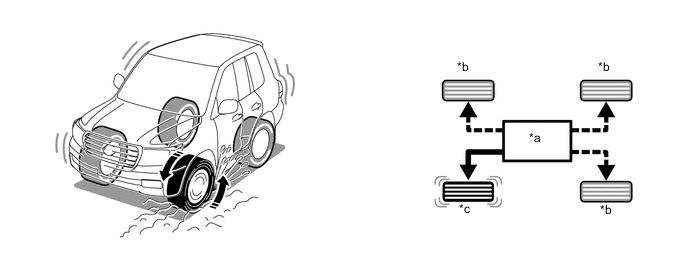
*a Driving Force *b No Traction *c Slipping - -
-
-
Effectiveness of A-TRC
-
The effectiveness of the A-TRC is as follows:
-
Off-road drivability that is equivalent to having the center differential locked and limited slip differential on both front and rear differentials has been realized.
-
This function makes the operation of the differential lock switches basically unnecessary to ensure the ease of driving.
-
While realizing the off-road drivability that is equivalent to having the center and rear differentials locked, as compared to the differential gear in the locked state, the prevention of tight corner braking phenomenon ensures the ease of nimble steerability.
-
-
-
Vehicle Stability Control (VSC)
-
The followings are two examples that can be considered as circumstances in which the tires exceed their lateral grip limit. The VSC is designed to help control the vehicle behavior by controlling the engine output and the brakes at each wheel when the vehicle is under one of the conditions indicated below.
-
When the front wheels lose grip in relation to the rear wheels (front wheel skid tendency).
-
When the rear wheels lose grip in relation to the front wheels (rear wheel skid tendency).

*a Front Wheel Skid Tendency *b Rear Wheel Skid Tendency
-
Method for Determining Vehicle Condition
-
To determine the condition of the vehicle, sensors detect the steering angle, vehicle speed, vehicle's yaw rate, and vehicle's lateral acceleration, which are then calculated by the skid control ECU.
-
Determining Front Wheel Skid
-
Whether the vehicle is in the state of the front wheel skid or not is determined by the difference between the target yaw rate and the vehicle's actual yaw rate. When the vehicle's actual yaw rate is smaller than the yaw rate (a target yaw rate that is determined by the vehicle speed and steering angle) that should be rightfully generated when the driver operates the steering wheel, it means the vehicle is making a turn at a greater angle than the locus of travel. Thus, the skid control ECU determines that there is a large tendency to front wheel skid.

*a Actual Locus of Travel (Actual Yaw Rate) *b Locus of Travel Based on the Target Yaw Rate -
Determining Rear Wheel Skid
-
Whether the vehicle is in the state of the rear wheel skid or not is determined by the values of the vehicle's slip angle and the vehicle's slip angular velocity (time-dependent changes in the vehicle's slip angle). When the vehicle's slip angle and the slip angular velocity are large, the skid control ECU determines that the vehicle has a large rear wheel skid tendency.

*a Travel Direction of Vehicle's Center or Gravity *b Slip Angle *c Movement of Vehicle - -
-
-
Method for VSC Operation
-
When the skid control ECU determines that the vehicle has a tendency to front wheel skid or rear wheel skid, it decreases the engine output and applies the brake of a front or rear wheel to control the vehicle's yaw moment.
-
The basic operation of the VSC is described below. However, the control method differs depending on the vehicle's characteristics and driving conditions.
-
Dampening Front Wheel Skid
-
When the skid control ECU determines that there is a large front wheel skid tendency, it counteracts in accordance with the extent of that tendency. The skid control ECU controls the engine output and applies the brake of the front wheel of the outer circle in the turns and rear wheels in order to restrain the front wheel skid tendency.
Figure 6. Dampening a Front Wheel Skid (Marking a Right Turn)
*a Control Moment - - 
Brake Force - - -
Dampening Rear Wheel Skid
-
When the skid control ECU determines that there is a large rear wheel skid tendency, it counteracts in accordance with the extent of that tendency. It applies the brakes of the front and rear wheels of the outer circle of the turn, and generates an outward moment of inertia in the vehicle, in order to help restrain the rear wheel skid tendency. Along with the reduction in the vehicle speed caused by the brake force, the excellent vehicle's stability is ensured.
-
In some cases, the skid control ECU applies the brake of the rear wheels as necessary.
Figure 7. Dampening a Rear Wheel Skid (Marking a Right Turn)

*a Control Moment - - Brake Force - -
-
-
-
Trailer Sway Control
-
General
-
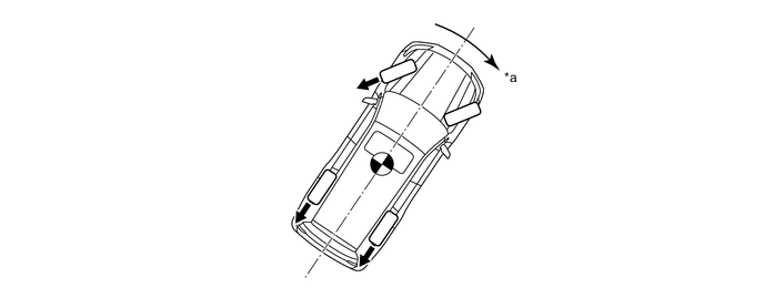
If the vehicle is towing a trailer with an inappropriate hitch load, trailer sway could be caused by crosswinds, or by imbalance caused by load or the driver's steering. Trailer sway control reduces trailer sway by controlling the engine output and the braking of each wheel.
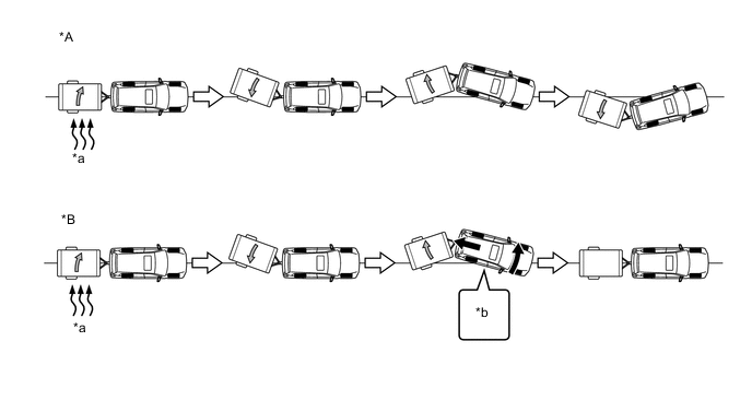
*A Models without Trailer Sway Control *B Models with Trailer Sway Control *a Side Wind *b Brake Control + Engine Output Control Note
-
Trailer sway control is a part of the VSC function. Accordingly, if the VSC OFF mode or VSC is not functioning normally, trailer sway control will not operate.
-
Trailer sway control will be unable to stabilize the vehicle if a trailer is being towed which cannot be physically controlled due to the influence of the vehicle, road surface, driving conditions and so on.
-
-
-
Trailer Sway Control Operation
-
The skid control ECU detects the occurrence of trailer sway based on signals from the yaw rate and deceleration sensor and the steering angle sensor.
-
Trailer sway can be reduced by decelerating the vehicle. When the skid control ECU detects trailer sway, it controls the brakes of each wheel while simultaneously requesting engine output control from the ECM and reducing vehicle speed.
-
Moreover, by using brake control to reduce the yaw moment caused by trailer sway, trailer sway can be reduced more quickly than by simply decelerating the vehicle.
-
The slip indicator light on the combination meter flashes when trailer sway control is in operation. Also, the stop light illuminates to inform vehicles behind that the vehicle is decelerating.
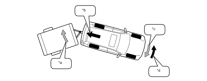
*a Trailer Sway *b Deceleration Force Caused by Brake Control and Engine Output Control *c Yaw Moment Caused by Trailer Sway *d Control Moment Caused by Brake Control 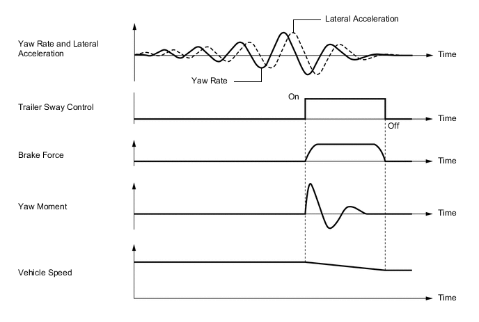
-
-
-
Hill-start Assist Control
-
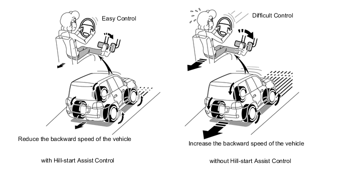
When the vehicle starts off on a steep or slippery hill, the vehicle could descend backward while the driver switches from the pedal brake to the accelerator pedal, thus making it difficult for the vehicle to start off. To prevent this from occurring, hill-start assist control temporarily (approximately 5 seconds at the maximum) applies the brakes to the 4 wheels in order to reduce the backward speed of the vehicle.
-
Without hill-start assist control, the driver must quickly and precisely switch from the brake pedal to the accelerator pedal. With hill-start assist control, however, the driver can start off easily and operate the pedal in a relaxed manner because hill-start assist control reduces the backward speed of the vehicle.
-
The hill-start assist control operates when all of the following conditions have been met:
Hill-start Assist Control Operate Condition
-
The shift lever is in the D or S positions.
-
The brake pedal is not pressed.
-
The skid control ECU has detected the backward movement of the vehicle when the driver is starting off on a hill.
-
-
-
CRAWL with Turn Assist Function
-
General
-
The CRAWL is a driving support system that regulates the engine output and the brake force, enabling the vehicle to be driven at a constant speed on rough ground or slippery roads.
-
When driving through a tight corner that cannot easily be passed through without cutting the steering wheel in the opposite direction, a control is implemented by using the turn assist function to improve turning performance in response to the driver's steering while constant low speed is maintained by CRAWL control, thus reducing the driver's steering operation.
-
-
CRAWL Operation
-
When the vehicle drives across rough grounds such as extremely bumpy rough roads, the driver needs to pay attention to the steering, braking and acceleration operations. However, with the CRAWL, the driver can concentrate on steering, without worrying about the accelerator pedal or brake pedal.
-
The CRAWL ensures good vehicle stability in situations such as when the vehicle is running on a slippery or steep road because the chances of the wheels spinning or locking are minimized by regulating the engine output and the brake force.
-
Each indicator lights and multi-information display operate as follows:
Indicator Light Condition CRAWL Indicator Light Turn Assist Indicator Light Slip Indicator Light CRAWL Operates (Only CRAWL) ○ - ▲ Operates (CRAWL and Turn Assist Function) ○ ○ ▲ Operates → Control Releases ▲ → X X X Operates → Control Releases (Only Turn Assist Function) ○ X ▲ Stops Control Temporarily ▲ ▲* X System Malfunctions - - ○ Operates → System Malfunctions ▲ → X X ○ Tech Tips
○: Illuminates
▲: Blinks
X: Turns off
-: Not applicable
Multi-information Display Condition Multi-information Display Master Warning Indicator Light CRAWL Operates (Only CRAWL) CRAWL Operates - Operates (CRAWL and Turn Assist Function) CRAWL Operates - Operates → Control Releases CRAWL Has Been Deactivated - Operates → Control Releases (Only Turn Assist Function) Turn Assist Function Has Been Deactivated - Stops Control Temporarily - - System Malfunctions Check VSC ○ Operates → System Malfunctions CRAWL Not Available Select L4 and Shift to [D] or [R] Position - CRAWL Not Available Check System Operation Conditions Turn Assist Function Not Available Activate CRAWL Control Turn Assist Function Not Available Check System Operation Conditions
-
-
CRAWL Operation Condition
-
When the CRAWL ON/OFF switch is pressed with all of the following conditions met, the CRAWL starts operating. The activation of the control causes the CRAWL indicator light to illuminate and the slip indicator light to blink.
CRAWL Operation Condition
-
Shift position is in any position other than P or N.
-
Transfer is L4.
-
2nd start switch is off.
-
ATF temperature is not too high.
-
Hydraulic brake booster temperature is not too high.
-
VSC system is operating normally.
-
Driver's door is closed.
Tech Tips
When the 2nd start switch is on, the CRAWL starts with only the brake control activated. In this case, the same operation indicator as that of the normal operation remains on.
-
-
When the vehicle speed exceeds approximately 25 km/h (16 mph) while the CRAWL is operating, the CRAWL will be suspended and the CRAWL indicator light will flash. In this case, the CRAWL will resume when the vehicle speed decreases below the said vehicle speed.
-
When any one of the following conditions is met, the skid control buzzer will sound, the CRAWL indicator light will start flashing, and the CRAWL will terminate. Also, when the operation is terminated through the CRAWL ON/OFF switch, the buzzer will not sound and the indicator light will go off.
CRAWL Operation Termination Condition
-
CRAWL ON/OFF switch is turned off.
-
Shift position is in any position other than P or N.
-
Transfer is changed to H4.
-
Driver's door is opened.
-
ATF temperature is too high.
-
Brake actuator temperature is too high.
-
VSC malfunctions. (If this happens, take appropriate actions such as stopping the vehicle.)
-
Target vehicle speed cannot be reached and the skid control ECU determines that the CRAWL cannot operate.
-
-
When the 2nd start switch is operated (turned on) while the CRAWL is operating, only the engine control is terminated, the brake control continues. In this case, the same operation indicator as that of the normal operation will remain on.
-
-
Turn Assist Function
-
The driver's intention to turn is judged in accordance with a steering sensor signal, thus controlling and increasing the brake hydraulic pressure of the rear wheels in the inner side of turning.
-
The rear wheels in the inner side of turning are locked [the wheel speed is 0 km/h (0 mph)] and the brake hydraulic pressure is maintained. When the wheels have been locked for a certain amount of time, brake hydraulic pressure will be reduced. As a result, the brake hydraulic pressure is controlled and increased until the wheels are locked again after they have started to move.
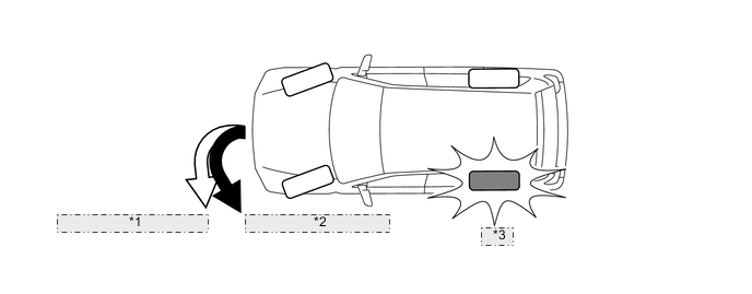
*1 Turn Assist Function Off *2 Turn Assist Function On *3 Brake
-
-
Turn Assist Function Operation Condition
-
When all of the following conditions are met, the turn assist function will operate. When the turn assist function can be operated, the turn assist indicator light will turn on.
Turn Assist Function Operation Conditions
-
The CRAWL is on.
-
The turn assist switch is on.
-
The center differential lock switch is off.
-
Vehicle speed is 10 km/h (6.2 mph) or less.
-
The accelerator pedal and brake pedal are not depressed.
-
The shift lever is in D or S.
-
Steering angle is large.
-
-
-
-
-
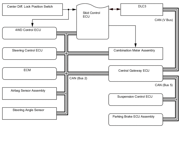
System Diagram

-
Layout of Main Components
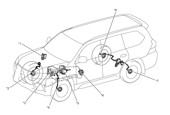
*1 ECM *2 Front Speed Sensor RH *3 Engine Room Relay Block
-
BRK LP Relay (Brake Light Relay)
*4 Front Speed Sensor LH *5 Hydraulic Brake Booster
-
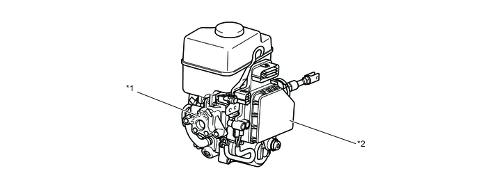
Skid Control ECU
-
Brake Booster with Accumulator Pump Assembly
-
Brake Fluid Level Warning Switch
*6 Transfer Shift Actuator Assembly
-
Center Diff. Lock Position Switch
*7 Rear Speed Sensor LH *8 Rear Speed Sensor RH 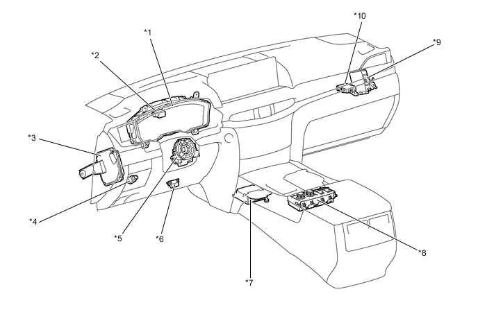
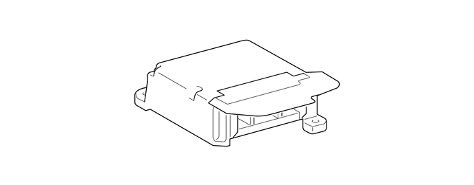
*1 Combination Meter Assembly *2 Stop Light Control Relay Assembly *3 Steering Control ECU *4 Stop Light Switch *5 Steering Angle Sensor *6 DLC3 *7 Airbag Sensor Assembly *8 Integration Control and Panel Assembly
-
VSC OFF Switch
-
Turn Assist ON/OFF Switch
-
CRAWL ON/OFF Switch
-
CRAWL Speed/MTS Mode Select Switch
*9 4WD Control ECU *10 Central Gateway ECU -
-
Function of Main Components
Component Function Hydraulic Brake Booster
-
Assists with the brake pedal effort applied to the brake pedal.
-
Changes the brake fluid path based on the signals from the skid control ECU during the operations of the multi-terrain ABS, EBD, brake assist, A-TRC, VSC, trailer sway control, hill-start assist control, and CRAWL in order to control the fluid pressure that is applied to the wheel cylinders.
Hydraulic Brake Booster Master Cylinder Pressure Sensor Detects the master cylinder pressure. Accumulator Pressure Sensor Detects the accumulator pressure. Pressure Control Sensor* Detects the control hydraulic pressure output by the accumulator. Brake Fluid Level Warning Switch Detects the brake fluid level. Skid Control ECU Judges the vehicle driving condition based on signals from each sensor, and sends brake control signals to the brake actuator. Solenoid Relay Supplies or cuts off power to control solenoid valves and switching solenoid valves in the brake actuator. Motor Relay Supplies or cuts off power to pump motor. Combination Meter Assembly Brake Warning Light
-
Lights up to alert the driver when a malfunction occurs in the EBD or skid control ECU.
-
Lights up to alert the driver that the hydraulic pressure of the accumulator in the hydraulic brake booster has decreased.
-
Lights up to alert the driver when the brake fluid in the reservoir tank reaches the low level.
ABS Warning Light Lights up to alert the driver when the skid control ECU detects a malfunction in the Multi-terrain ABS, EBD or brake assist system. Slip Indicator Light Blinks to inform the driver when the A-TRC, VSC, trailer sway control, hill-start assist control, or CRAWL is operated. TRC OFF Indicator Light Lights up to inform the driver when the A-TRC OFF mode is entered using the VSC OFF switch. VSC OFF indicator Light
-
Lights up to inform the driver that the VSC OFF mode is selected using the VSC OFF switch.
-
When the skid control ECU detects a malfunction and determines that the A-TRC, VSC or trailer sway control is not available, the VSC OFF indicator light blinks to alert the driver.
CRAWL Indicator Light Lights up to inform the driver when the CRAWL ON/OFF switch is turned on. Turn Assist Indicator Light Lights up to inform the driver when the turn assist function is operated. Multi-terrain Indicator Light Lights up to inform the driver when the multi-terrain select is operated. Center Diff. Lock Indicator Light Lights up to inform the driver when the center differential condition is locked. Multi-information Display Informs the driver of the status of the brake control system. Master Warning Light Informs the driver of the status of the brake control system. Integration Control and Panel Assembly VSC OFF Switch
-
By pressing the switch, only the A-TRC engine control is brought to a halt.
-
By pressing the switch for more than 3 seconds, both the A-TRC and VSC stop operating.
CRAWL ON/OFF Switch Turns the CRAWL on and off. CRAWL Speed Selector Switch / MTS Mode Switch
-
Used to select the target vehicle speed when the CRAWL is active.
-
Used to select the road mode when the multi-terrain select is active.
Turn Assist Function Switch Turns the turn assist function on and off. Speed Sensor Detects the wheel speed and rotating direction of each of 4 wheels. Steering Angle Sensor Detects the steering direction and angle of the steering wheel. Airbag Sensor Assembly Yaw Rate Sensor Detects the vehicle's yaw rate. Linear G Sensor Detects the vehicle's acceleration and deceleration in the forward, rearward, and lateral directions. Stop Light Control Relay Turns on the stop light during hill-start assist control, or CRAWL, or dynamic radar cruise control, or pre-collision brake operation. Stop Light Switch Detects the brake pedal depressing signal. ECM Controls the throttle valve opening angle based on the signals receives from the skid control ECU, in order to control the engine output. Also, sends the throttle valve opening angle signal, accelerator pedal position signal, and engine speed signal to the skid control ECU. 4WD Control ECU Detects the transfer condition shifted in the L4 and sends the L4 signal to the skid control ECU. *: Models with pre-crash safety system
-
-
Construction of Main Components
-
Hydraulic Brake Booster
-
General
-
The hydraulic brake booster consists of the brake pressure generation portion, power supply portion, and brake control portion.
-
The brake pressure generation portion consists of a master cylinder and brake booster and a master cylinder pressure sensor.
-
The power supply portion is a pump, pump motor, relief valve, reservoir tank, brake fluid level warning switch, accumulator and accumulator pressure sensor.
-
The brake control portion consists of a skid control ECU and master cylinder solenoid.
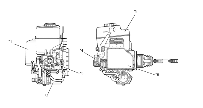
*1 Accumulator *2 Pump and Pump Motor *3 Master Cylinder Solenoid
-
Switching Solenoid Valves
-
Control Solenoid Valves
*4 Master Cylinder and Brake Booster *5 Brake Master Cylinder Reservoir Sub-assembly
-
Brake Fluid Level Warning Switch
*6 Skid Control ECU -
-
-
Components of Hydraulic Brake Booster
-
The hydraulic brake booster consists of the following components:
Components Function Brake Pressure Generation Portion Master Cylinder and Brake Booster
-
Generates the hydraulic pressure that is provided to the wheel cylinders during normal brake.
-
Regulates the accumulator pressure in accordance with the pedal effort that is applied to the brake pedal and introduce this pressure to the booster chamber in order to provide a power assist to the brakes.
Master Cylinder Pressure Sensor Detects the master cylinder pressure and outputs this signal to the skid control ECU. Power Supply Portion Pump and Pump Motor Draws up the brake fluid from the reservoir tank and provides high hydraulic pressure to the accumulator. Accumulator Stores the hydraulic pressure that was generated by the pump. The accumulator is filled with high-pressure nitrogen gas. Accumulator Pressure Sensor Monitors the hydraulic pressure of the accumulator and outputs this signals for the pump motor control. Relief Valve Returns the brake fluid to the reservoir tank to prevent excessive pressure if the pump operates continuously due to a malfunction of the pressure sensor. Reservoir Tank Stores the brake fluid. Brake Fluid Level Warning Switch Detects the low brake fluid level. Brake Control Portion Switching Solenoid Valves Switches the brake hydraulic path when the brake control system is activated. Control Solenoid Valves Controls the hydraulic pressure that is applied to the wheel cylinders during brake control. Pressure Control Sensor* In the brake control of the pre-crash safety system, hydraulic pressure is applied from the accumulator to each wheel cylinder, generating braking force automatically. The control pressure sensor detects the control hydraulic pressure at that time. Skid Control ECU
-
Judges the vehicle driving condition based on signals from each sensor, and controls Multi-terrain ABS with EBD, brake assist, A-TRC, VSC, trailer sway control, hill-start assist control, and CRAWL.
-
Operates the brake booster pump assembly to control brake booster accumulator assembly pressure based on accumulator pressure sensor signal.
*: Models with pre-crash safety system
Figure 8. Hydraulic Circuit
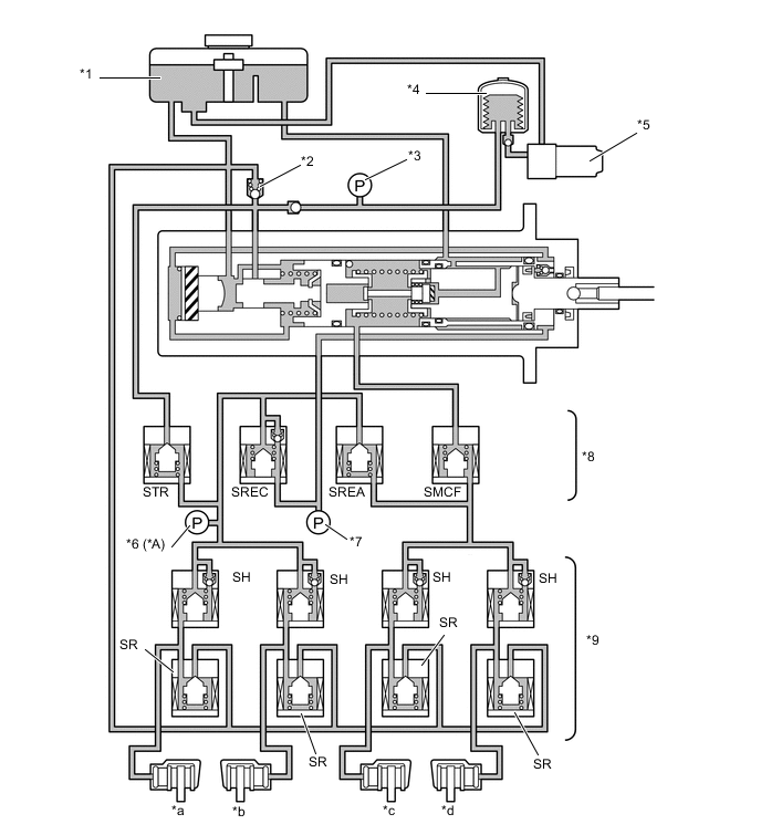
*A Models with Pre-crash Safety System - - *1 Reservoir Tank *2 Relief Valve *3 Accumulator Pressure Sensor *4 Accumulator *5 Pump and Pump Motor *6 Pressure Control Sensor *7 Master Cylinder Pressure Sensor *8 Switching Solenoid Valve *9 Control Solenoid Valve - - *a Rear LH *b Rear RH *c Front LH *d Front RH STR Traction Solenoid Valve (Accumulator Cut Solenoid Valve) SREC Regulator Cut Solenoid Valve SREA Regulator Apply for Front Solenoid Valve SMCF Master Cut for Front Solenoid Valve SH Pressure Holding Solenoid Valve SR Pressure Reduction Solenoid Valve -
-
-
-
Master Cylinder and Brake Booster
-
Construction
-
The master cylinder and brake booster consists of the brake booster portion, master cylinder portion, and regulator portion. These are positioned coaxially to achieve a simple and compact construction.
-
The brake booster portion consists of an operation rod, a power piston and a booster chamber.
-
The master cylinder portion consists of a master cylinder piston (large diameter piston and small diameter piston), a return spring and a center valve.
-
The regulator portion consists of a regulator piston, a return spring, a spool valve, a reaction rod, and a rubber reaction disc.
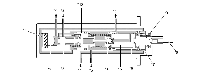
*1 Rubber Reaction Disc *2 Reaction Rod *3 Spool Valve *4 Center Valve *5 Master Cylinder Inner Piston (Small Diameter Piston) *6 Master Cylinder Outer Piston (Large Diameter Piston) *7 Booster Chamber *8 Operation Rod *9 Power Piston *10 Regulator Piston *a To Rear Brake *b To Front Brake *c To Reservoir Tank *d From Accumulator
-
-
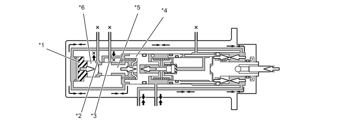
Operation
-
Pressure Increase (Low Pressure)
-
The pedal operation force transmits as follows: Operation Rod → Power Piston → Master Cylinder Piston (Small Diameter Piston)
-
The load setting of the master cylinder's return spring is higher than that of the regulator piston's return spring. Therefore, the regulator piston gets pushed before the fluid in the master cylinder becomes compressed.
-
The spool valve closes the port A (between the reservoir tank and booster chamber) and opens the port B (between the reservoir tank and accumulator). Then, the pressurized brake fluid is introduced into the booster chamber to provide a power assist to the pedal effort. The pressure of the pressurized brake fluid is transmitted to the large diameter master cylinder piston.
-
This time, the power assist overcomes the force of the master cylinder's return spring. This causes the fluid in the master cylinder to become compressed and increased the pressure that is applied to the front brakes. At the same time, the pressure in the booster chamber increases the pressure that is applied to the rear brakes.
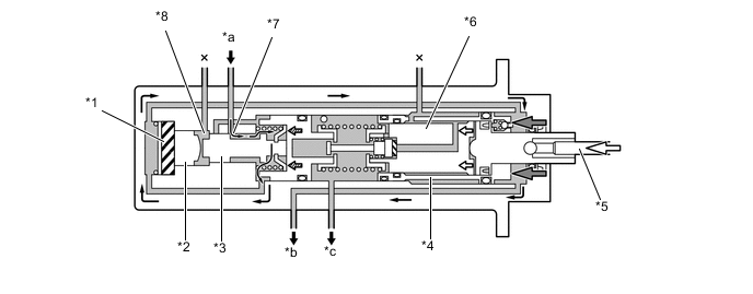
*1 Rubber Reaction Disc *2 Reaction Rod *3 Spool Valve *4 Master Cylinder Outer Piston (Large Diameter Piston) *5 Operation Rod *6 Master Cylinder Inner Piston (Small Diameter Piston) *7 Port B *8 Port A *a From Accumulator *b To Rear Brake *c To Front Brake - - -
During the initial stage of the brake operation, the booster pressure that is applied to the rubber reaction disc is small. Therefore, a return force in the rightward direction is not applied to the spool valve via the reaction rod.
-
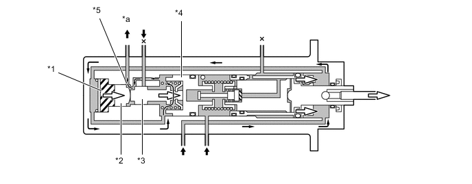
Pressure Increase (High Pressure)
-
In contrast to the time when the pressure is low, when the pressure is high, the booster pressure that is applied to the rubber reaction disc increases. Accordingly, the rubber reaction disc deforms and causes a return force in the rightward direction to be applied to the spool valve via the reaction rod. Therefore, in contrast to the time when the pressure is low, a greater reaction force is transmitted to the brake pedal.
-
As a result, a variable servo mechanism is realized, in which the servo ratio is lower during high pressure than during low pressure.
*1 Rubber Reaction Disc *2 Reaction Rod *3 Spool Valve - - *a Booster Pressure - - -
Holding
-
This is a state in which the force that is applied via the brake pedal and the master cylinder pressure are in balance.
-
The forces that are applied to the front and the rear of the regulator piston, in other words, the forces that are generated by the master cylinder pressure and the regulator pressure become balanced. This causes the spool valve to close both the port B (between the reservoir tank and the accumulator) and the port A (between the booster chamber and reservoir tank). As a result, the brake is in the holding state.
*1 Rubber Reaction Disc *2 Port A *3 Port B *4 Regulator Valve *5 Spool Valve *6 Reaction Rod -
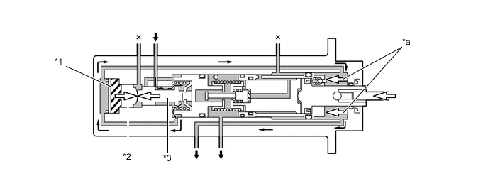
Pressure Reduce
-
When the pressure that is applied to the brake pedal is released, the master cylinder pressure decreases. Then, the regulator piston's return (rightward) force becomes relatively greater, causing the regulator piston and the spool valve to retract. As a result, the port A between the reservoir tank and the booster chamber opens.
-
The booster pressure becomes reduced in this state, creating a balance that corresponds to the change of brake pedal application force. This process occurs constantly to reduce the booster pressure and the master cylinder pressure in accordance with the force that is applied via the brake pedal.
*1 Rubber Reaction Disc *2 Reaction Rod *3 Spool Valve *4 Regulator Valve *5 Port A - - *a To Reservoir Tank - - -
During Power Supply Malfunction
-
If the accumulator pressure is affected by any malfunction, no hydraulic pressure will be supplied to the booster chamber. For this reason, a power assist cannot be provided to the force that is applied via the brake pedal and the pressure to the rear brakes cannot be increased. Since there is no pressurized brake fluid in the large diameter master cylinder piston at this time, the piston does not move from the original position.
-
However, the pressure to the front brakes will be increased at the small diameter master cylinder piston in accordance with the pedal effort applied to the brake pedal.
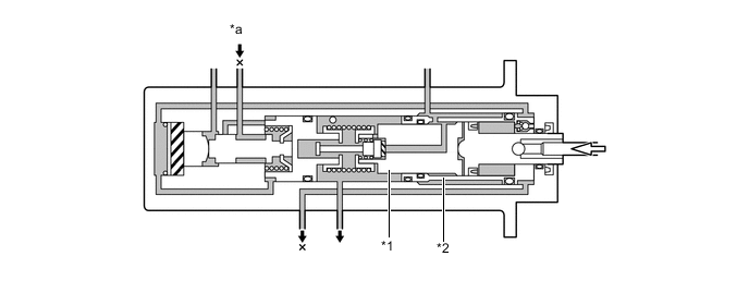
*1 Master Cylinder Inner Piston (Small Diameter Piston) *2 Master Cylinder Outer Piston (Large Diameter Piston) *a Accumulator Pressure - - -
Front Brake System Malfunction
-
If the front brake system malfunctions, the master cylinder piston is moved by the booster chamber pressure but the hydraulic pressure does not increase. The rear brake system operates the same as in the normal operation.
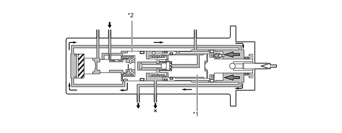
*1 Master Cylinder Piston *2 Regulator Valve
-
-
-
Pump and Accumulator
-
General
-
A plunger type pump is used. This pump is driven by the pump motor, and generates high hydraulic pressure, and then supplies the hydraulic pressure to the accumulator.
-
Inside the accumulator, the high-pressurized nitrogen gas is charged and sealed. In addition, metallic bellows-formed tube is used, in order to enhance the gastight performance of the accumulator.
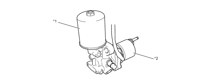
*1 Accumulator *2 Pump Motor Figure 9. Simplified Diagram
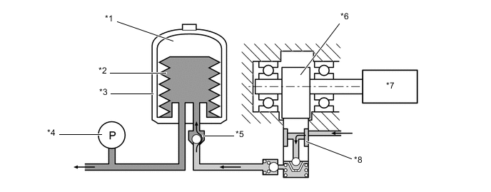
*1 Nitrogen Gas *2 Bellows-formed Tube *3 Accumulator *4 Accumulator Pressure Sensor *5 Check Valve *6 Camshaft *7 Pump Motor *8 Pump
-
-
Operation
-
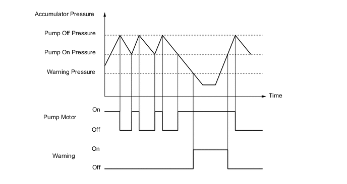
The power supply portion operates based on the accumulator pressure sensor signal as shown in the timing chart below.
-
When the accumulator pressure drops to "pump on pressure", the skid control ECU operates the pump and pump motor.
-
When the accumulator pressure increases to "pump off pressure", the skid control ECU stops the pump and pump motor.
-
When the accumulator pressure drops below the "warning pressure" level, the skid control ECU illuminates the warning and indicator lights, displays messages on the multi-information display, and sounds the multi buzzer in the combination meter assembly.
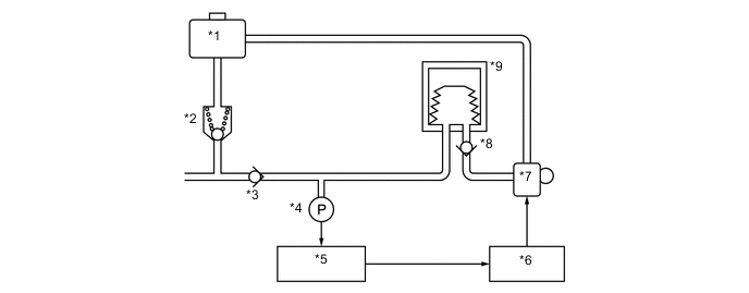
*1 Reservoir Tank *2 Relief Valve *3 Check Valve *4 Accumulator Pressure Sensor *5 Skid Control ECU *6 Motor Relays *7 Pump Motor *8 Check Valve *9 Accumulator - - Figure 10. Timing Chart
-
-
-
Master Cylinder Solenoid
-
General
-
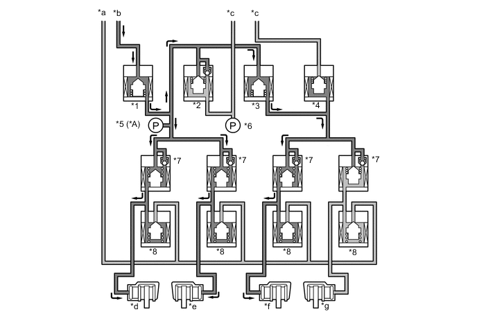
The master cylinder solenoid consists of switching solenoid valves and control solenoid valves.
*1 Master Cylinder Solenoid *2 Skid Control ECU Figure 11. Hydraulic Circuit
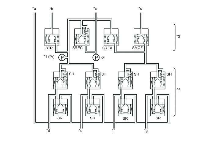
*A Models with Pre-crash Safety System - - *1 Pressure Control Sensor *2 Master Cylinder Pressure Sensor *3 Switching Solenoid Valve *4 Control Solenoid Valve *a To Reservoir Tank *b From Accumulator *c From Master Cylinder and Brake Booster *d Rear LH *e Rear RH *f Front LH *g Front RH - - STR Traction Solenoid Valve (Accumulator Cut Solenoid Valve) SREC Regulator Cut Solenoid Valve SREA Regulator Apply for Front Solenoid Valve SMCF Master Cut for Front Solenoid Valve SH Pressure Holding Solenoid Valve SR Pressure Reduction Solenoid Valve
-
-
Solenoid Valve
-
There are 2 types of solenoid valves: the switching solenoid valve and the control solenoid valve. The pressure increase mode, the pressure holding mode, and the pressure reduction mode are effected based on the combination of these valves that are turned on and off, in order to control the hydraulic pressure that is applied to each of the wheel cylinders.
-
A total of 4 switching solenoid valves are used: 2 (SMCF, SREA) in the front brake fluid path, 1 (SREC) in the rear brake fluid path, and 1 (STR) in the accumulator fluid path. The switching valves open and close in accordance with the control signals from the skid control ECU in order to switch the respective brake fluid paths.
-
A total of 8 control solenoid valves are used for the 4 wheels (2 types per wheel: pressure holding solenoid and pressure reduction solenoid).
-
-
-
Console Switch
-
The CRAWL ON/OFF switch, turn assist ON/OFF switch, CRAWL speed/MTS mode select switch, and VSC OFF switch are built into the integration control and panel assembly (console module switch), integrating them on the console and allowing the driver to keep his/her driving posture when using those traction and drive related switches.
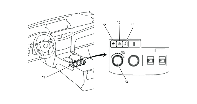
*1 Integration Control and Panel Assembly *2 Turn Assist ON/OFF Switch *3 CRAWL Speed/MTS Mode Select Switch *4 VSC OFF Switch *5 CRAWL ON/OFF Switch - - -
The VSC OFF switch can stop the engine control of the VSC function and A-TRC function regardless of the position of the transfer range or the condition of the center differential switch.
VSC OFF Switch Operation Contents Press the switch once
-
The A-TRC engine control stops operating.
-
The control can be resumed by pressing the switch again or when the vehicle speed increases.
Press and hold the switch for more than 3 seconds when the vehicle is stationary.
-
The A-TRC and VSC stop operating.
-
The A-TRC and VSC can be resumed by pressing the switch.
Tech Tips
-
The A-TRC and VSC functions control brake hydraulic pressure and engine output to ensure vehicle stability. Therefore, operate the VSC OFF switch (stop the operation of the A-TRC and VSC functions) only when it is necessary.
-
When the transfer is in the L4 range and the center differential is not locked, even when both the A-TRC and VSC are not operating, vehicle speeds less than 15 km/h (9 mph) may cause the A-TRC to be activated, however, this is not a malfunction.
-
-
The CRAWL control is switched between on and off by operating the CRAWL ON/OFF switch.
-
The CRAWL control vehicle speed is changed by operating the CRAWL speed select switch.
-
The turn assist control is switched between on and off by operating the turn assist ON/OFF switch.
-
The multi-terrain select road mode (MUD and SAND, LOOSE ROCK, MOGUL, ROCK and DIRT, ROCK) can be selected with the MTS mode select switch.
-
-
Speed Sensor
-
General
-
The active type speed sensor can detect the wheel rotation. This sensor contains a sensor IC, which consists of the Magnetic Resistance Elements (MREs).
-
The sensor rotor, which consists of N and S poles that are arranged in a circle, is integrated with the inner race of the hub bearing.
-
The differences between the passive type speed sensor (containing a pick-up coil to detect speeds) and the active type speed sensors are described below:
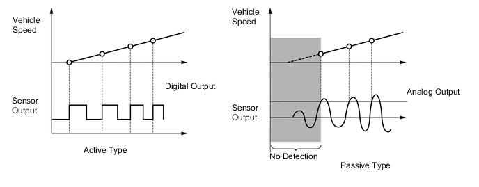
Figure 12. Active Type Speed Sensor
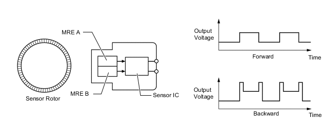
Figure 13. Passive Type Speed Sensor
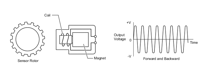
Type Active Passive Direction Detection Possible to judge both forward and backward Impossible to judge the wheel rotation direction Detection Speed Approx. 0 km/h (0 mph) 5 km/h (3 mph) or more Weight Approx. 1/3 of passive type -
-
-
Detection Method
-
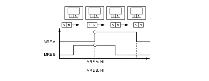
To detect the rotation direction, the output waves are used to determine the relationship of the pulses that are generated by the 2 MREs.
-
Upon receiving this signal, the sensor IC outputs a forward or backward wave.
Figure 14. Forward
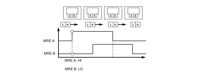
Figure 15. Backward
-
To detect the vehicle speed, the frequency of the output pulses is used. Because the active type sensor outputs digital pulses, it can detect vehicle speeds even when the vehicle is nearly stationary.
-
-
-
Yaw Rate Sensor and Deceleration Sensor
-
A yaw rate sensor and deceleration sensor are built into the airbag sensor assembly.
-
These sensors detects the yaw rate and lateral and longitudinal acceleration and deceleration, and sends this signal to the suspension control ECU.
-
-
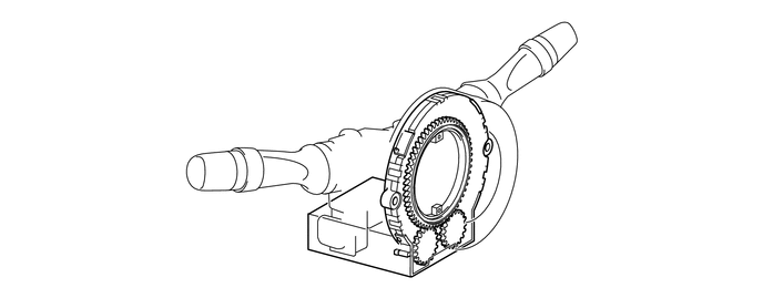
Steering Angle Sensor
-
A steering angle sensor is provided in the combination switch area. This sensor detects the amount of steering effort and the direction of steering wheel.
-
The sensor assembly contains two sets of magnetic reluctance elements that detect the rotational movement of a magnet that is built into the detection gear. Thus, the sensor detects the changes that occur in the magnetic reluctance elements along with the rotational movement of the detection gear, in order to detect the rotational movement of the steering wheel.
-
-
-
System Operation
-
Normal Braking
-
During normal braking, all solenoid valves are turned off.
*A Models with Pre-crash Safety System - - *1 Traction Solenoid Valve (Accumulator Cut Solenoid Valve) (STR) *2 Regulator Cut Solenoid Valve (SREC) *3 Regulator Apply for Front Solenoid Valve (SREA) *4 Master Cut for Front Solenoid Valve (SMCF) *5 Master Cylinder Pressure Sensor *6 Master Cylinder Pressure Sensor *7 Pressure Holding Solenoid Valve (SH) *8 Pressure Reduction Solenoid Valve (SR) *a To Master Cylinder Reservoir Sub-assembly *b From Brake Booster Accumulator Assembly *c From Master Cylinder *d Rear LH *e Rear RH *f Front LH *g Front RH - -
-
-
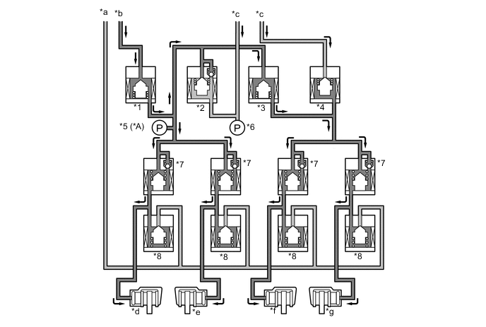
Multi-terrain ABS with EBD Operation
-
During braking, the load moves in the longitudinal direction of the vehicle. This reduces the ground load of the rear wheels, making them more susceptible to slipping than the front wheels.
-
The skid control ECU calculates speed and deceleration of each wheel, and checks wheel slipping condition based on signals from the 4 wheel speed sensors and airbag sensor assembly (yaw rate sensor and deceleration sensor signals) as well as the engine output information transmitted from the ECM.
-
The skid control ECU compares the speed sensor signals of the front and rear, judges the slipping condition of the rear wheel, and operates the EBD.
-
If the wheel is likely to be locked, the skid control ECU controls the pressure holding solenoid valve and pressure reduction solenoid valve as multi-terrain ABS operation in the following 3 modes: increase, hold, and reduce.
Figure 16. EBD Operation
*A Models with Pre-crash Safety System - - *1 Traction Solenoid Valve (Accumulator Cut Solenoid Valve) (STR) *2 Regulator Cut Solenoid Valve (SREC) *3 Regulator Apply for Front Solenoid Valve (SREA) *4 Master Cut for Front Solenoid Valve (SMCF) *5 Master Cylinder Pressure Sensor *6 Master Cylinder Pressure Sensor *7 Pressure Holding Solenoid Valve (SH) *8 Pressure Reduction Solenoid Valve (SR) *a To Master Cylinder Reservoir Sub-assembly *b From Brake Booster Accumulator Assembly *c From Master Cylinder *d Rear LH *e Rear RH *f Front LH *g Front RH - - Figure 17. Multi-terrain ABS Operation
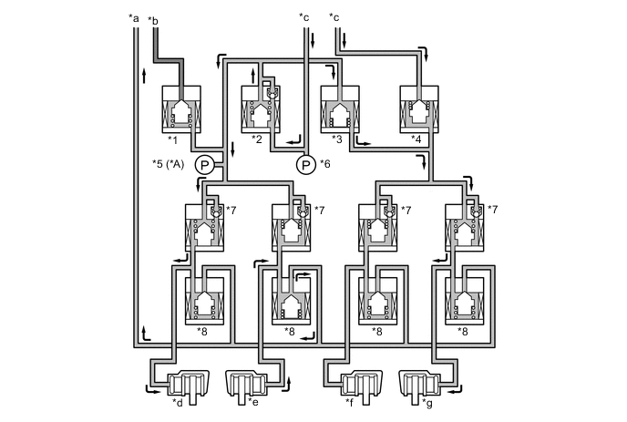
*A Models with Pre-crash Safety System - - *1 Traction Solenoid Valve (Accumulator Cut Solenoid Valve) (STR) *2 Regulator Cut Solenoid Valve (SREC) *3 Regulator Apply for Front Solenoid Valve (SREA) *4 Master Cut for Front Solenoid Valve (SMCF) *5 Master Cylinder Pressure Sensor *6 Master Cylinder Pressure Sensor *7 Pressure Holding Solenoid Valve (SH) *8 Pressure Reduction Solenoid Valve (SR) *a To Master Cylinder Reservoir Sub-assembly *b From Brake Booster Accumulator Assembly *c From Master Cylinder *d Rear LH (Increase) *e Rear RH (Reduction) *f Front LH (Holding) *g Front RH (Increase) - - Item Not Activated Multi-terrain ABS with EBD Activated Increase Mode Holding Mode Reduction Mode SREC Off (Open) ← ← ← STR Off (Closed) ← ← ← Front Brake SMCF*1 Off (Open) On (Closed) ← ← SREA*1 Off (Closed) On (Open) ← ← SH Off (Open) ← On (Closed) ← SR Off (Closed) ← ← On (Open) Wheel Cylinder Pressure - Increase Hold Reduce Rear Brake SH*2 Off (Open) ← On (Closed) ← SR Off (Closed) ← ← On (Open) Wheel Cylinder Pressure - Increase Hold Reduce Tech Tips
*1: While the front wheels are in multi-terrain ABS operation, SMCF and SREA are on. While only rear wheels are in multi-terrain ABS operation, SMCF and SREA are off.
*2: During EBD operation, only SH for both rear wheels is on (close).
-
-
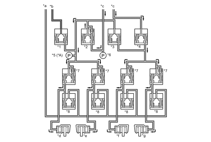
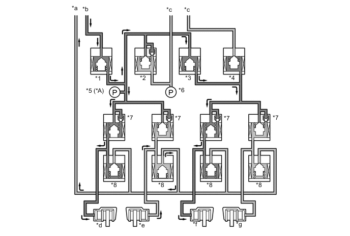
Brake Assist Operation
-
If an emergency braking situation has occurred, it is detected by the skid control ECU based on the vehicle speed signal from the speed sensor, the brake pedal application speed from the master cylinder pressure sensor, and the signal representing the amount of pedal effort. Then, the skid control ECU actuates each solenoid valve. As a result, the pressure from the accumulator is applied to the wheel cylinders. The accumulator pressure that is applied to the wheel cylinders generates a higher pressure than the master cylinder.
Figure 18. Brake Assist Operation
*A Models with Pre-crash Safety System - - *1 Traction Solenoid Valve (Accumulator Cut Solenoid Valve) (STR) *2 Regulator Cut Solenoid Valve (SREC) *3 Regulator Apply for Front Solenoid Valve (SREA) *4 Master Cut for Front Solenoid Valve (SMCF) *5 Master Cylinder Pressure Sensor *6 Master Cylinder Pressure Sensor *7 Pressure Holding Solenoid Valve (SH) *8 Pressure Reduction Solenoid Valve (SR) *a To Master Cylinder Reservoir Sub-assembly *b From Brake Booster Accumulator Assembly *c From Master Cylinder *d Rear LH *e Rear RH *f Front LH *g Front RH - - Figure 19. Brake Assist Timing
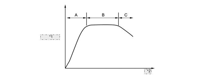
*1 Brake Force *2 Time Item Not Activated Brake Assist Activated A B C SREC Off (Open) On (Closed) ← Off (Open) STR Off (Closed) On (Open) ← Off (Closed) Front Brake SMCF Off (Open) On (Closed) ← ← SREA Off (Closed) On (Open) ← ← SH Off (Open) ← On (Closed) ← SR Off (Closed) ← ← On (Open) Rear Brake SH Off (Open) ← On (Closed) ← SR Off (Closed) ← ← On (Open) Wheel Cylinder Pressure - Increase Hold Reduce
-
-
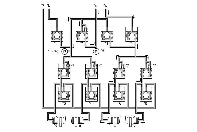
A-TRC Operation
-
Based on the vehicle speed that has been calculated from each speed sensor and signals of the airbag sensor assembly (yaw rate sensor and deceleration sensor signals), the skid control ECU computes the target control speed in accordance with the transfer range. The skid control ECU compares the target control speed and the speed of the wheels to determine whether or not slippage exists. Upon detecting slippage, the skid control ECU controls the solenoid valve of the hydraulic brake booster to control the brake fluid pressure that is applied to the slipping wheel. When the wheel speed becomes lower than the target control speed, the skid control ECU stops increasing the brake fluid pressure.
-
The engine output control of the A-TRC function varies in accordance with the range in which the transfer is engaged. When the transfer is engaged in the H4 range, this function effects engine output control that varies between stability-priority and drivability-priority in accordance with the amount of pedal effort applied to the accelerator pedal. When the transfer is engaged in the L4 range, it affects engine output control on a drivability-priority basis.
-
As shown in the table below, the target control speed and the brake fluid pressure control vary in accordance with the transfer range.
Road Condition Transfer Range Control Outline Ordinary Road H4 Target Control Speed Vehicle Speed + Slip Rate (H range set value) Control designed to ensure the ease of driving on low-friction roads, dirt roads, and general roads. Brake Control Gradual Fluid Pressure Control Engine Output Control Effects control only when center differential lock switch is off Rocky or Rough Road L4 Target Control Speed Vehicle Speed + Slip Rate (L range set value) Control designed for rugged off-road driving. Brake Control Sudden fluid Pressure Control Engine Output Control Not Control Downhill L4 + 1st gear Target Control Speed Vehicle speed when deceleration slippage has been determined during downhill driving. Designed for rugged, off-road downhill driving with the engine brake applied. It prevents the acceleration of the vehicle that could be caused by the release of the engine brake. Brake Control Fluid pressure control to the front wheels Note
When the A-TRC is operating continuously while the vehicle is being driven on a slippery surface, the temperature of the actuator in the hydraulic brake booster increases. After a prescribed length of time elapses, the skid control ECU alerts the driver of this condition by causing the multi buzzer to sound, and the slip indicator light to illuminate. Also, the A-TRC operation is momentarily interrupted to protect the actuator. When the temperature of the actuator decreases, the slip indicator light turns off, and the A-TRC is automatically restored to an operating state.
-
The fluid pressure control of the A-TRC independently controls the brake of each wheel by operating the individual solenoid valves in accordance with the signals received from the skid control ECU. The brake of each wheel is controlled in the following 3 modes: pressure reduction, pressure hold, and pressure increase modes.
Figure 20. A-TRC Operation
*A Models with Pre-crash Safety System - - *1 Traction Solenoid Valve (Accumulator Cut Solenoid Valve) (STR) *2 Regulator Cut Solenoid Valve (SREC) *3 Regulator Apply for Front Solenoid Valve (SREA) *4 Master Cut for Front Solenoid Valve (SMCF) *5 Master Cylinder Pressure Sensor *6 Master Cylinder Pressure Sensor *7 Pressure Holding Solenoid Valve (SH) *8 Pressure Reduction Solenoid Valve (SR) *a To Master Cylinder Reservoir Sub-assembly *b From Brake Booster Accumulator Assembly *c From Master Cylinder *d Rear LH (Increase) *e Rear RH (Reduction) *f Front LH (Increase) *g Front RH (Holding) - - Item Not Activated A-TRC Activated Increase Mode Holding Mode Reduction Mode SREC Off (Open) On (Closed) ← ← STR Off (Closed) On (Open) ← ← Front Brake SMCF Off (Open) On (Closed) ← ← SREA Off (Closed) On (Open) ← ← SH Off (Open) ← On (Closed) ← SR Off (Closed) ← ← On (Open) Wheel Cylinder Pressure - Increase Hold Reduce Rear Brake SH Off (Open) ← On (Closed) ← SR Off (Closed) ← ← On (Open) Wheel Cylinder Pressure - Increase Hold Reduce
-
-
VSC Operation
-
General
-
Based on the information provided by various sensors, switches, and the ECM, the skid control ECU determines the vehicle's yaw moment. Then, the skid control ECU controls the fluid pressure that is generated by the pump and pump motor and applies it by way of the solenoid valves to the brake wheel cylinder of each wheel in the following 3 modes: pressure reduction, pressure hold, and pressure increase modes. As a result, the tendency of the front wheels or the rear wheels to skid is restrained.
-
At this time, the skid control ECU outputs a VSC operate signal to the ECM and the combination meter assembly. Upon receiving this signal, the ECM affects fuel injection to regulate the engine output. The combination meter assembly causes the slip indicator light to blink.
-
-
Front Wheel Skid Restraining (Turning to the Right)
-
In front wheel skid restraining control, the brakes of the rear wheels and front wheel of the outer side of the turn is applied. Also, depending on whether the brake is on or off and the condition of the vehicle, there are circumstances in which the brake might not be applied to the wheels even if those wheels are targeted for braking. The diagram below shows the hydraulic circuit in the pressure increase mode, as it restrains a front wheel skid condition while the vehicle makes a right turn.
-
In other operating modes, the pressure holding valve and the pressure reduction valve are turned on/off according to the multi-terrain ABS with EBD operation pattern.
Figure 21. VSC Operation (Front Wheel Skid Restraining)
*A Models with Pre-crash Safety System - - *1 Traction Solenoid Valve (Accumulator Cut Solenoid Valve) (STR) *2 Regulator Cut Solenoid Valve (SREC) *3 Regulator Apply for Front Solenoid Valve (SREA) *4 Master Cut for Front Solenoid Valve (SMCF) *5 Master Cylinder Pressure Sensor *6 Master Cylinder Pressure Sensor *7 Pressure Holding Solenoid Valve (SH) *8 Pressure Reduction Solenoid Valve (SR) *a To Master Cylinder Reservoir Sub-assembly *b From Brake Booster Accumulator Assembly *c From Master Cylinder *d Rear LH *e Rear RH *f Front LH *g Front RH - - Item Not Activated VSC Activated Increase Mode Holding Mode Reduction Mode SREC Off (Open) On (Closed) ← ← STR Off (Closed) On (Open) ← ← Front Brake SMCF Off (Open) On (Closed) ← ← SREA Off (Closed) On (Open) ← ← SH RH Off (Open) On (Closed) ← ← LH Off (Open) ← On (Closed) ← SR RH Off (Closed) ← ← ← LH Off (Closed) ← ← On (Open) Wheel Cylinder Pressure RH - - - - LH - Increase Hold Reduce Rear Brake SH Off (Open) ← On (Closed) ← SR Off (Closed) ← ← On (Open) Wheel Cylinder Pressure - Increase Hold Reduce Note
-
When the brake pedal is depressed while the VSC is in operation, the brake pedal becomes more difficult to depress than it used to be, however, this is not a malfunction.
-
When the center differential is locked, the VSC is prohibited from operating. At this time, the center differential indicator light and the VSC OFF indicator light turns on. When the center differential is unlocked, the center differential indicator light and the VSC OFF indicator light go off, and the VSC turns on.
-
-
Rear Wheel Skid Restraining Control (Turning to the Right)
-
In rear wheel skid restraining control, the front wheel brake of the outer side of the turn is applied. Also, depending on whether the brake is on or off and the condition of the vehicle, there are circumstances in which the brake might be applied to the rear brake of the outer side the turn. The diagram below shows the hydraulic circuit in the pressure increase mode, as it restrains a rear wheel skid condition while the vehicle makes a right turn.
-
In other operating modes, the pressure holding valve and the pressure reduction valve are turned on/off according to the multi-terrain ABS with EBD operation pattern.
Figure 22. VSC Operation (Rear Wheel Skid Restraining)

*A Models with Pre-crash Safety System - - *1 Traction Solenoid Valve (Accumulator Cut Solenoid Valve) (STR) *2 Regulator Cut Solenoid Valve (SREC) *3 Regulator Apply for Front Solenoid Valve (SREA) *4 Master Cut for Front Solenoid Valve (SMCF) *5 Master Cylinder Pressure Sensor *6 Master Cylinder Pressure Sensor *7 Pressure Holding Solenoid Valve (SH) *8 Pressure Reduction Solenoid Valve (SR) *a To Master Cylinder Reservoir Sub-assembly *b From Brake Booster Accumulator Assembly *c From Master Cylinder *d Rear LH *e Rear RH *f Front LH *g Front RH - - Item Not Activated VSC Activated Increase Mode Holding Mode Reduction Mode SREC Off (Open) On (Closed) ← ← STR Off (Closed) On (Open) ← ← Front Brake SMCF Off (Open) On (Closed) ← ← SREA Off (Closed) On (Open) ← ← SH RH Off (Open) On (Closed) ← ← LH Off (Open) ← On (Closed) ← SR RH Off (Closed) ← ← ← LH Off (Closed) ← ← On (Open) Wheel Cylinder Pressure RH - - - - LH - Increase Hold Reduce Rear Brake SH Off (Open) ← ← ← SR Off (Closed) ← ← ← Wheel Cylinder Pressure - - - - -
-
-
Trailer Sway Function Operation
-
The operation of the solenoid valves under the trailer sway function is the same as the VSC operation.
-
-
Hill-start Assist Control Operation
-
Based on the information provided by various sensors, switches, and the ECM, the skid control ECU computes the backward movement of the vehicle that occurs when the vehicle starts off on a hill. Then, the skid control ECU controls the fluid pressure that is generated by the pump and pump motor and applies it by way of the solenoid valves to the brake wheel cylinder of each wheel in the following 3 modes: pressure reduction, pressure hold, and pressure increase modes.
-
The skid control ECU determines the state of the backward movement of the vehicle while the driver is attempting to drive uphill, based on the speed sensors and the park/neutral position switch.
-
The skid control ECU determines the gradient of the hill, the acceleration state of the vehicle, the locked state and the direction of rotation of each wheel through the speed sensors and the airbag sensor assembly (yaw rate sensor and deceleration sensor signals). Then, the skid ECU computes the amount of brake control that prevents the wheels from locking.
-
During this operation, the skid control ECU outputs a hill-start assist control operation signal to the combination meter assembly. This causes the slip indicator light to blink, outputs signals to the stop light control relay which turns on the stop light.
-
The hill-start assist control operates for approximately 5 seconds. At this time, the skid control ECU informs the driver by the slow and intermittent sound of the multi buzzer. After that, the skid control ECU alerts the driver by using the quick and intermittent sound of the multi buzzer, and gradually releases the brake hydraulic pressure in order to end the hill-start assist control operation.
Figure 23. Hill-start Assist Control Operation
*A Models with Pre-crash Safety System - - *1 Traction Solenoid Valve (Accumulator Cut Solenoid Valve) (STR) *2 Regulator Cut Solenoid Valve (SREC) *3 Regulator Apply for Front Solenoid Valve (SREA) *4 Master Cut for Front Solenoid Valve (SMCF) *5 Master Cylinder Pressure Sensor *6 Master Cylinder Pressure Sensor *7 Pressure Holding Solenoid Valve (SH) *8 Pressure Reduction Solenoid Valve (SR) *a To Master Cylinder Reservoir Sub-assembly *b From Brake Booster Accumulator Assembly *c From Master Cylinder *d Rear LH (Increase) *e Rear RH (Reduction) *f Front LH (Increase) *g Front RH (Holding) - - Item Not Activated Hill-start Assist Control Activated Increase Mode Holding Mode Reduction Mode SREC Off (Open) On (Closed) ← ← STR Off (Closed) On (Open) ← ← Front Brake SMCF Off (Open) On (Closed) ← ← SREA Off (Closed) On (Open) ← ← SH Off (Open) ← On (Closed) ← SR Off (Closed) ← ← On (Open) Wheel Cylinder Pressure - Increase Hold Reduce Rear Brake SH Off (Open) ← On (Closed) ← SR Off (Closed) ← ← On (Open) Wheel Cylinder Pressure - Increase Hold Reduce Note
When the hill-start assist control is operating continuously while the vehicle is being driven on a slippery surface, the temperature of the actuator in the hydraulic brake booster increases. After a prescribed length of time elapses, the skid control ECU alerts the driver of this condition by causing the slip indicator light to illuminate. Also, the hill-start assist control operation is momentarily interrupted to protect the actuator. When the temperature of the actuator decreases, the slip indicator light turns off, and the hill-start assist control is automatically restored to an operating state.
-
-
CRAWL Operation
-
Based on the information provided by various sensors, switches, and the ECM, the skid control ECU determines the conditions that enable the CRAWL to operate. The skid control ECU computes the target vehicle speed (approximately 1 to 5 km/h, 1 to 3 mph) to control the vehicle speed, and the target wheel speeds to control the wheel slipping. The target vehicle speed can be changed using the speed selector switch.
-
When the vehicle speed differs from the target speed, the engine output is regulated. When the wheel speeds differ from the target speeds, the hydraulic brake pressure of the wheels is regulated.
-
The skid control ECU controls the fluid pressure that is generated by the pump and pump motor and applies it by way of the solenoid valves to the brake wheel cylinder of each wheel in the following 3 modes: pressure reduction, pressure hold, and pressure increase modes.
Figure 24. CRAWL Operation
*A Models with Pre-crash Safety System - - *1 Traction Solenoid Valve (Accumulator Cut Solenoid Valve) (STR) *2 Regulator Cut Solenoid Valve (SREC) *3 Regulator Apply for Front Solenoid Valve (SREA) *4 Master Cut for Front Solenoid Valve (SMCF) *5 Master Cylinder Pressure Sensor *6 Master Cylinder Pressure Sensor *7 Pressure Holding Solenoid Valve (SH) *8 Pressure Reduction Solenoid Valve (SR) *a To Master Cylinder Reservoir Sub-assembly *b From Brake Booster Accumulator Assembly *c From Master Cylinder *d Rear LH (Increase) *e Rear RH (Reduction) *f Front LH (Increase) *g Front RH (Holding) - - Item Not Activated CRAWL Activated Increase Mode Holding Mode Reduction Mode SREC Off (Open) On (Closed) ← ← STR Off (Closed) On (Open) ← ← Front Brake SMCF Off (Open) On (Closed) ← ← SREA Off (Closed) On (Open) ← ← SH Off (Open) ← On (Closed) ← SR Off (Closed) ← ← On (Open) Wheel Cylinder Pressure - Increase Hold Reduce Rear Brake SH Off (Open) ← On (Closed) ← SR Off (Closed) ← ← On (Open) Wheel Cylinder Pressure - Increase Hold Reduce Note
-
Prior to starting off, check the CRAWL indicator light. If the indicator light is blinking, the CRAWL brake control will work but the CRAWL engine control will not.
-
When the CRAWL is operating continuously, the temperature of the actuator in the hydraulic brake booster increases. After a prescribed length of time elapses, the skid control ECU alerts the driver of this condition by causing the multi buzzer to sound intermittently for approximately 3 seconds, slip indicator light to illuminate, and the CRAWL indicator light to blink. Also, the CRAWL operation is momentarily interrupted to protect the actuator. When the temperature of the actuator decreases, the slip indicator light turns off, and the CRAWL is automatically restored to an operating state.
-
When the CRAWL continues operating, the ATF temperature may increase too much. If this happens, the ATF temperature warning indicator in the multi-information display turns on and the CRAWL operation is momentarily interrupted to protect the automatic transmission. If the vehicle continues to be driven in this situation, ATF leakage or automatic transmission malfunctions may result. Therefore, the driver should immediately stop the vehicle in a safe area and select shift position P or N to let the ATF cool down enough. When the ATF temperature decreases, the ATF temperature warning indicator turns off. Then, the CRAWL becomes available.
-
-
-
Engine Output Control
-
During a A-TRC, VSC, or CRAWL operation, the skid control ECU outputs a brake control operation signal to the ECM. Upon receiving this signal, the ECM effects throttle control to regulate the engine output.
-
-
Initial Check
-
Each time the engine switch is turned IG-ON, and the vehicle reaches approximately speed of 6 km/h (4 mph) or more, the skid control ECU performs the initial check.
-
The functions of each solenoid valve, pump and pump motor in the hydraulic brake booster are checked in order.
-
-
-
Diagnosis
-
If the skid control ECU detects a malfunction in the brake control system, the warning lights or indicator light illuminate. At the same time, a Diagnostic Trouble Code (DTC) is stored in the memory of the skid control ECU.
-
This system has a sensor signal check (test mode) function.
-
For details of DTCs and check function, refer to the Repair Manual.
-
-
Fail-safe
-
If a failure occurs in the skid control ECU, sensors or hydraulic brake booster, the system continues effecting brake control by excluding the failed area and using only the areas that are operating normally.
-