SUSPENSION AND AXLE
-
General
-
The suspension system, which consists of 4-wheel active height control suspension and adaptive variable suspension, offers both comfort and convenience to achieve high driving performance for on-road and off-road driving.
-
The front suspension uses spring rate control to improve driving performance during on-road driving.
-
4-wheel related control is used to improve driving performance during on-road and off-road driving.
-
The vehicle height control is provided with an easy access control function for improved convenience.
-
The damping force control uses non-linear H∞ control.
Control Outline Vehicle Height Control The amount of fluid to be sent through the height control valve into the shock absorbers for each of the wheels is regulated in accordance with the manual switch operation and driving conditions. Damping Force Control The optimum damping force can be obtained by controlling the damping force control actuators arranged on each of the wheels in accordance with the manual switch operation and driving conditions. Spring Rate Control (for Front Suspension) The spring rate can be controlled by switching the fluid passage to the gas chambers arranged on both the left and right front shock absorbers. 4-wheel Related Control The hydraulic tubes for the shock absorbers are channeled through the center suspension control cylinder, therefore, the amount of hydraulic pressure for each of the shock absorbers can be individually adjusted via the center suspension control cylinder in accordance with the driving conditions. Tech Tips
-
To summarize, H∞ control is a theory for designing a controller that meets the control specifications that are represented by the H∞ norm (a unit of measurement of the transfer function of the system). When this is expanded into a non-linear system, it is called "non-linear H∞ control".
-
The "H" is the initial letter of the mathematician named Hardy (who studied the stability of control systems) who advocated the mathematical space that is handled by this control logic. The "∞" represents the ∞ norm, which is one of the mathematical units used for measuring the size of the signals.
Note
-
Before jacking the vehicle or raising it on a hoist, make sure that the engine switch is off.
-
If the vehicle must be lifted up when the engine switch is ON (IG), turn the height control off switch off to suspend vehicle height control operations in the suspension control ECU.
-
-
-
-
System Diagram
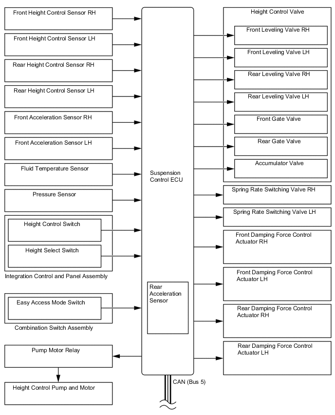
-
Layout of Main Components
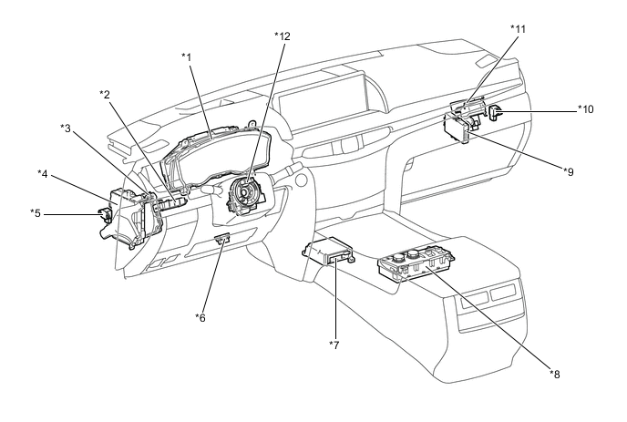
*1 Combination Meter *2 Combination Switch Assembly
-
Easy Access Mode Switch
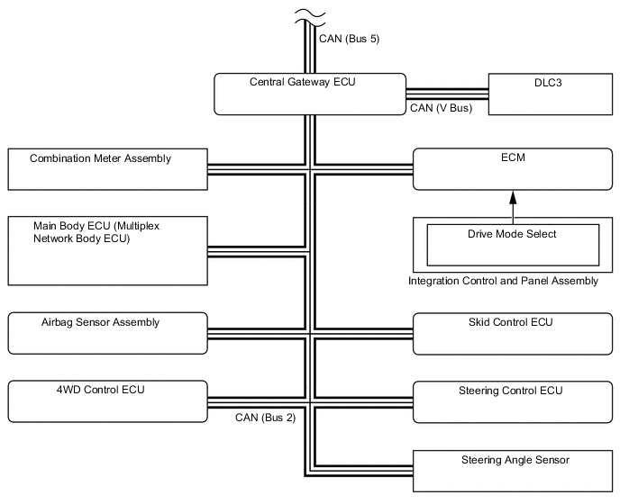
*3 Steering Control ECU *4 Main Body ECU (Multiplex Network Body ECU) *5 Front Acceleration Sensor *6 DLC3 *7 Airbag Sensor Assembly *8 Integration Control and Panel Assembly
-
Drive Mode Select
-
Height Control Switch
-
Height Select Switch
*9 Central Gateway ECU *10 Front Acceleration Sensor *11 4WD Control ECU *12 Steering Angle Sensor 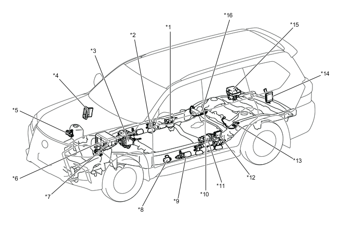
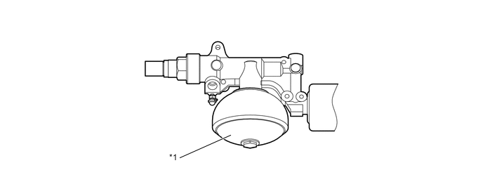
*1 Rear Suspension Control Accumulator Assembly
-
Damping Force Control Actuator
-
No. 1 Gas Chamber
-
Relief Gas Chamber
*2 Front Suspension Control Valve Assembly
-
Spring Rate Switching Valve
-
No. 1 Gas Chamber
*3 Skid Control ECU *4 ECM *5 Front Height Control Sensor RH *6 Engine Room Relay Block
-
Pump Motor Relay
*7 Front Height Control Sensor LH *8 Relief Gas Chamber *9 Front Suspension Control Accumulator Assembly
-
Damping Force Control Actuator
-
No. 2 Gas Chamber
*10 Suspension Control Pump Accumulator *11 Center Suspension Control Cylinder *12 Height Control Valve *13 Rear Height Control Sensor LH *14 Suspension Control ECU *15 Height Control Pump and Motor *16 Rear Height Control Sensor RH -
-
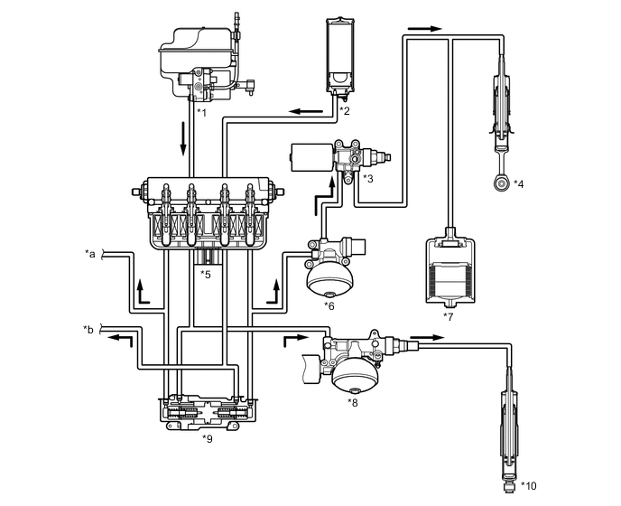
Suspension Tubing Diagram
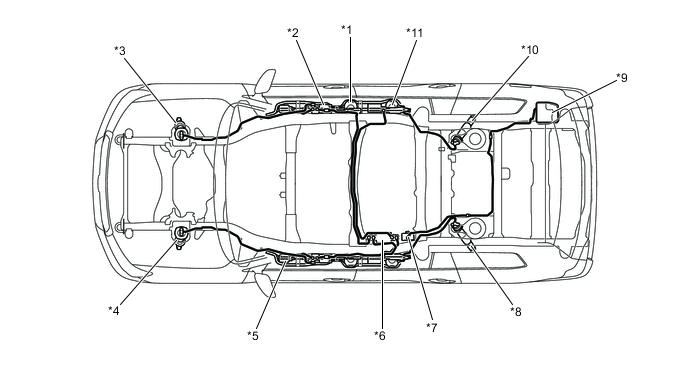
*1 Front Suspension Control Valve *2 Front Suspension Control Accumulator Assembly *3 Front Shock Absorber RH *4 Front Shock Absorber LH *5 Relief Gas Chamber *6 Height Control Accumulator *7 No. 1 Height Control Valve Assembly *8 Rear Shock Absorber LH *9 Height Control Pump and Motor Assembly *10 Rear Shock Absorber RH *11 Rear Suspension Control Accumulator Assembly - - -
Hydraulic Circuit
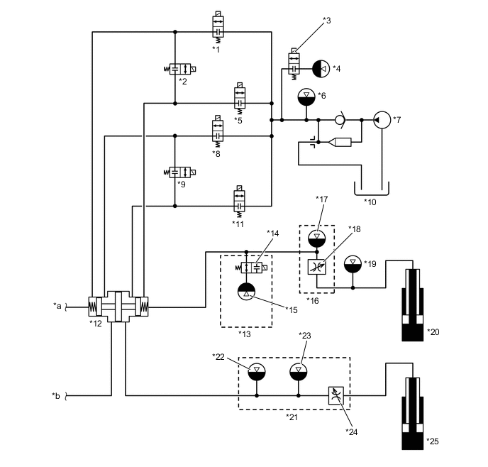
*1 Leveling Valve *2 Gate Valve *3 Accumulator Valve *4 Suspension Control Pump Accumulator *5 Leveling Valve *6 Pump Attenuator *7 Pump *8 Leveling Valve *9 Gate Valve *10 Reservoir Tank *11 Leveling Valve *12 Center Suspension Control Cylinder *13 Front Suspension Control Valve Assembly *14 Spring Rate Switching Valve *15 No. 1 Gas Chamber *16 Front Suspension Control Accumulator Assembly *17 No. 2 Gas Chamber *18 Damping Force Control Actuator *19 Relief Gas Chamber *20 Front Shock Absorber RH *21 Rear Suspension Control Accumulator Assembly *22 Relief Gas Chamber *23 No. 1 Gas Chamber *24 Damping Force Control Actuator *25 Rear Shock Absorber RH - - *a To Front Shock Absorber LH *b To Rear Shock Absorber LH -
Function of Main Components
Component Function Height Control Pump and Motor Pump and Pump Motor Generates the high hydraulic pressure that is necessary for raising the vehicle height. Reservoir Tank Maintains the amount of fluid that is returned during the LO position and the amount of fluid that is discharged during the HI position. Return Valve Opens and closes the fluid passage between the height control valve and the reservoir tank. Pressure Sensor Detects the pump's discharge pressure. Fluid Temperature Sensor Detects the fluid temperature. Pump Attenuator Dampens the hydraulic pulsation of the fluid that is discharged by the pump. Suspension Control Pump Accumulator Stores the hydraulic pressure to accelerate the speed in which the vehicle height is raised. Height Control Valve Leveling Valve Opens and closes the fluid passage between the pump and the gas chamber on the wheel. Gate Valve Opens and closes the fluid passage between the right and left shock absorbers. Accumulator Valve Opens and closes the fluid passage to the suspension control pump accumulator. Center Suspension Control Cylinder Mechanically operates in accordance with the pressure applied to the shock absorbers and optimally distributes the hydraulic pressure to each of the wheels. Front Suspension Control Valve Assembly Spring Rate Switching Valve Opens and closes the fluid passage to the No. 1 gas chamber. No. 1 Gas Chamber (Low spring rate) Acts like a gas spring by partially utilizing coil spring force. This is provided on the front wheels. Front Suspension Control Accumulator Assembly No. 2 Gas Chamber (High spring rate) Acts like a gas spring by partially utilizing coil spring force. This is provided on the front wheels. Damping Force Control Actuator Switches the damping force. Relief Gas Chamber (for Front Suspension) Protects hydraulic systems by restricting increase in the hydraulic pressure inside the hydraulic tubes. Rear Suspension Control Accumulator Assembly No. 1 Gas Chamber Acts like a gas spring by partially utilizing coil spring force. This is provided on the rear wheels. Relief Gas Chamber Protects hydraulic systems by restricting increase in the hydraulic pressure inside the hydraulic tubes. Damping Force Control Actuator Switches the damping force. Shock Absorber
-
Generates a damping force similar to the conventional shock absorber.
-
Includes a high-pressure main seal and high-pressure oil seal for friction reduction and further improvement of the sealing performance.
Combination Meter Multi-information Display
-
Displays the vehicle height and control conditions.
-
Displays a warning message when a system malfunction occurs.
Master Warning Light Illuminates when the warning message is displayed. Buzzer Sounds when the warning message is displayed. Easy Access Mode Indicator Light
-
Illuminates when the easy access mode switch is turned on.
-
Blinks while the easy access control is operating.
Integration Control and Panel Assembly Height Select Switch Selects the target vehicle height. Height Control Switch Prohibits the vehicle height control. Drive Mode Select Selects a damping force control mode. Combination Switch Assembly Easy Access Mode Switch Switches the easy access control between on and off. Height Control Sensor Detects the vehicle height. Steering Angle Sensor Detects the steering direction and angle of the steering wheel. Airbag Sensor Assembly Yaw Rate Sensor Detects the vehicle's yaw rate. Deceleration Sensor Detects the vehicle's longitudinal and lateral acceleration and deceleration. Acceleration Sensor 3 acceleration sensors are provided in total. The two of them are provided in the front of the vehicle and one is built into the suspension control ECU located in the rear of the vehicle. Thus, the acceleration sensors independently detect the vertical acceleration rate of the vehicle. Pump Motor Relay Controls the pump motor operation. Suspension Control ECU Controls the entire system by performing the calculations for height control, damping force control and spring rate control based on the signals received from the sensors and switches. Steering Control ECU Sends the VGRS control status signal to the suspension control ECU. Skid Control ECU Sends the speed sensor signal and brake control status signal to the suspension control ECU. 4WD Control ECU Sends the 4WD control status signal to the suspension control ECU. ECM
-
Sends the engine speed signal to the suspension control ECU
-
Sends the drive mode signal to the suspension control ECU
Main Body ECU (Multiplex Network Body ECU) Sends the engine switch status signal, door courtesy switch signal and suspension control switch signal to the suspension control ECU. -
-
Construction and Operation of Main Components
-
Height Control Pump and Motor
-
A system in which the pump, pump motor, reservoir tank, return valve, pump attenuator, pressure sensor, and fluid temperature sensor are integrated is used.
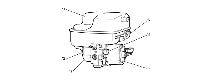
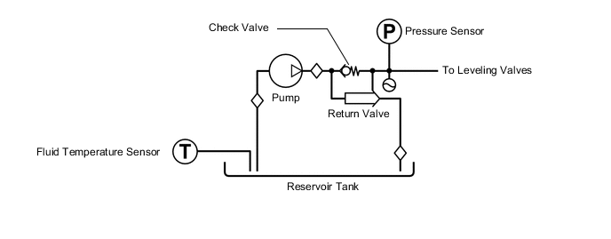
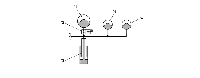
*1 Reservoir Tank *2 Pump Attenuator *3 Pump *4 Pump Motor *5 Pressure Sensor *6 Fluid Temperature Sensor Figure 1. Pump and Pump Motor Hydraulic Diagram
-
Pump
-
An external gear pump that contains less parts and excels in durability is used. Also, the pump is a pressure-loading type in which the discharge pressure of the pump itself is utilized and routed via the gear case to push on the side of the pump gear in order to reduce the internal leakage, thus making high-pressure discharge possible.
*1 Pump Gear *2 Gear Case *a Discharge *b High Pressure
-
-
Pump Motor
-
A DC motor with 4-pole brushes is used to realize excellent durability and high torque.

*1 Pump Motor *2 Brush *a Cross Section - -
-
-
Return Valve
-
The return valve opens and closes the fluid passage between the height control valve and the reservoir tank. The return valve has been simplified by adopting a construction in which the valve is closed by the flow of the discharged fluid.
-
Normally, a spring force is applied to the return valve to maintain the fluid passage between the height control valve and the reservoir tank open.
-
When the pump operates in order to raise the vehicle height, the pressure of the fluid that is discharged by the pump causes the return valve to move to the left of the diagram as illustrated.
-
Accordingly, the fluid passage between the height control valve and the reservoir tank closes, and the fluid that is discharged from the pump flows towards the height control valve.
Figure 2. Normal Condition

*1 Return Valve (Open) - - *a From Height Control Valve *b To Reservoir Tank Figure 3. Pump in Operation

*1 Return Valve (Close) - - *a To Height Control Valve *b From Pump
-
-
Pump Attenuator
-
The pump attenuator dampens the hydraulic pulsation of the fluid that is discharged by the pump.
-
A bellows type accumulator that is made of stainless steel, which offers excellent gas penetration resistance and good pulsation absorption performance, is used.
*1 Pump Attenuator *2 Reservoir Tank *a Nitrogen Gas *b Bellows *c Fluid Pressure - - Specifications Sealed Gas Nitrogen Gas Gas Chamber Volume 1.75 cc (0.11 cu in.) Sealed Gas Pressure 2.0 MPa (20.4 kgf/cm2, 290.1 psi)
-
-
-
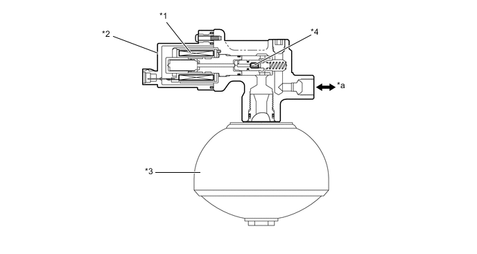
Suspension Control Pump Accumulator
-
A free piston type accumulator, which provides a large gas chamber capacity, is used for the suspension control pump accumulator.
-
When the vehicle height is being raised, the accumulator discharges the stored fluid to accelerate the raising speed.
*1 Free Piston - - *a Nitrogen Gas *b Cross Section *c Fluid *d B-B Cross Section *e View From A - - Specifications Sealed Gas Nitrogen Gas Gas Chamber Volume 945 cc (57.7 cu in.) Sealed Gas Pressure 5.9 MPa (60.0 kgf/cm2, 856 psi)
-
-
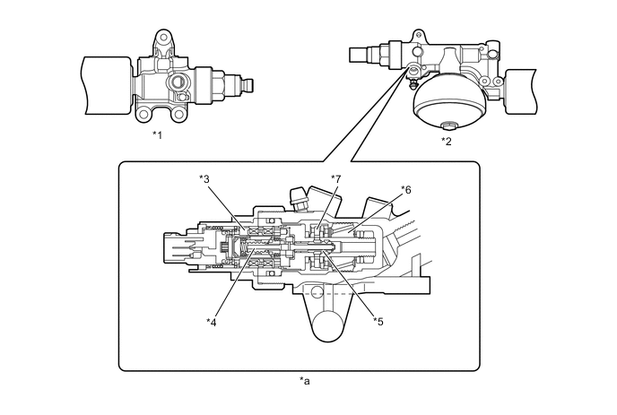
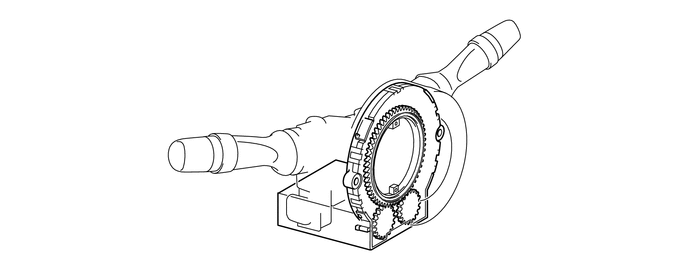
Height Control Valve
-
The height control valve is comprised of four leveling valves, two gate valves and an accumulator valve.
*1 Leveling Valve *2 Front Gate Valve *3 Accumulator Valve *4 Rear Gate Valve *a A-A Cross Section *b B-B Cross Section Figure 4. Arrangement Layout of Hydraulic Tubes
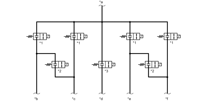
*1 Leveling Valve *2 Gate Valve *3 Accumulator Valve - - *a To Pump / Reservoir Tank *b Front Right *c Front Left *d Suspension Control Pump Accumulator *e Rear Left *f Rear Right
-
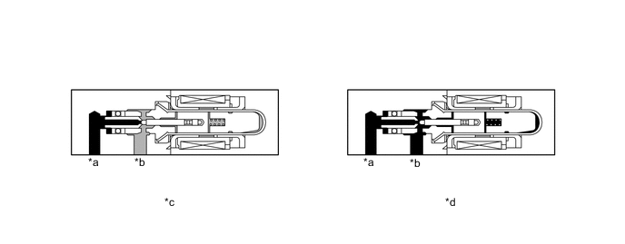
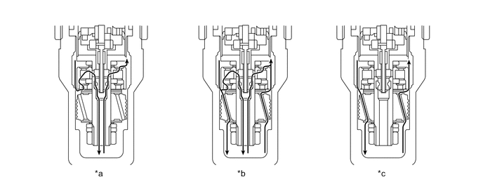
Leveling Valve
-
This valve opens and closes the fluid passage between the pump and the gas chamber located at each wheel. Normally, the fluid passage remains closed. During vehicle height control, the fluid passage opens in accordance with the signal received from the suspension control ECU.

*a Wheel Side *b Pump Side *c Close *d Open
-
-
Gate Valve
-
This valve is provided for both the front and rear sides. This valve opens and closes the fluid passage to both the left and right leveling valves. Normally, the fluid passage is closed. The fluid passage opens in accordance with signals from the suspension control ECU, thereby balancing the fluid pressure for both the left and right gas chambers.
*a Left Side *b Right Side *c Close *d Open
-
-
Accumulator Valve
-
This valve opens and closes the fluid passage between the pump and the suspension control pump accumulator. Normally, the fluid passage remains closed. When the vehicle height is being raised or the fluid is being stored in the suspension control pump accumulator, the solenoid valve opens in accordance with the signal received from the suspension control ECU.
*a Accumulator Side *b Pump Side *c Close *d Open
-
-
-
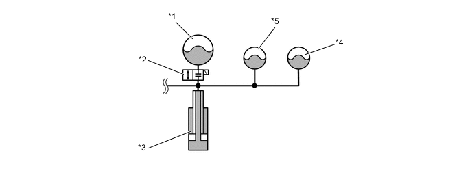
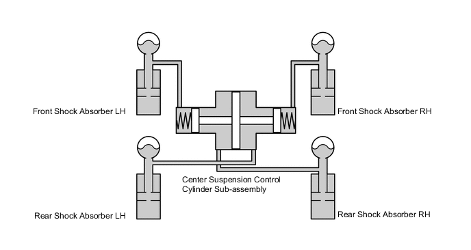
Center Suspension Control Cylinder
-
The center suspension control cylinder is comprised of four fluid chambers and a piston.
-
The fluid chambers are connected to each other via the hydraulic tubes from each of the shock absorbers. The center suspension control cylinder optimally distributes the hydraulic pressure for each of the wheels through the piston which operates in accordance with the input hydraulic pressure.
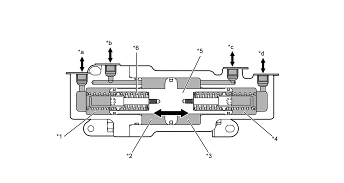
*1 Fluid Chamber 1 *2 Fluid Chamber 2 *3 Fluid Chamber 3 *4 Fluid Chamber 4 *5 Piston *6 Neutral Return Spring *a Front Left *b Rear Right *c Rear Left *d Front Right
-
-
Spring Rate Switching Valve
-
This valve is provided in the front suspension control valve assembly, and it opens and closes the fluid passage to the No. 1 gas chamber to perform spring rate control.
-
Normally, the fluid passage remains opened. During spring rate control, the fluid passage closes is accordance with the signal received from the suspension control ECU.
*1 Solenoid Valve *2 Spring Rate Switching Valve *3 No. 1 Gas Chamber (Low Compression Rate) *4 Poppet Valve *a To Shock Absorber - -
-
-
No. 1 Gas Chamber
-
The No. 1 gas chamber is provided for each of the wheels. This gas chamber is designed with a low compression rate utilizing a large-volume gas chamber.
-
The front No. 1 gas chamber is provided for the front suspension control valve assembly.
-
The rear No. 1 gas chamber is provided for the rear suspension control accumulator assembly.
-
The No. 1 gas chamber uses the bladder filter type hydro-pneumatic accumulator. A resin membrane is sandwiched between rubber layers to realize excellent gas penetration resistance.
-
The internal pressure of the gas chamber is varied by allowing the fluid to flow in and out of this gas chamber in order to raise or lower the vehicle height.
Figure 5. Front Suspension Control Valve Assembly

*1 No. 1 Gas Chamber (Low Compression Rate) - - Figure 6. Rear Suspension Control Accumulator Assembly
*1 No. 1 Gas Chamber (Low Compression Rate) - - 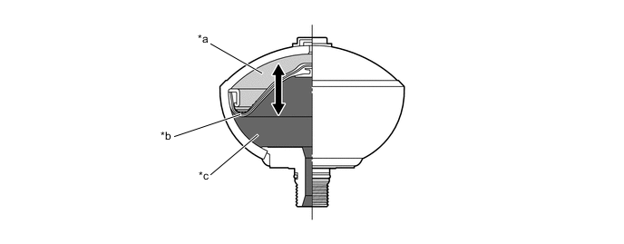
*a Gas Chamber (Nitrogen Gas) *b Bladder Filter *c Fluid Chamber - - Specifications No. 1 Gas Chamber Front Rear Sealed Gas Nitrogen Gas ← Gas Chamber Volume 400 cc (24.4 cu in.) ← Sealed Gas Pressure 2.26 MPa (23 kgf/cm2, 328 psi)
1.90 MPa (19 kgf/cm2, 276 psi)
-
-
No. 2 Gas Chamber
-
A No. 2 gas chamber is provided for the front suspension control accumulator assembly. This gas chamber is designed with a high compression rate utilizing a small-volume gas chamber.
-
The No. 2 gas chamber uses a metallic bellows type hydro-pneumatic accumulator, to prevent gas leakage.
-
The internal pressure of the gas chamber is varied by allowing the fluid to flow in and out of this gas chamber in order to raise or lower the vehicle height.
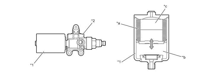
*1 No. 2 Gas Chamber (High Compression Rate) *2 Front Suspension Control Accumulator Assembly *a Metallic Bellows *b Fluid Chamber *c Gas Chamber (Nitrogen Gas) - - Specifications Sealed Gas Nitrogen Gas Gas Chamber Volume 120 cc (7.3 cu in.) Sealed Gas Pressure 1.8 MPa (18 kgf/cm2, 261 psi)
-
-
Relief Gas Chamber
-
A relief gas chamber is provided for each of the wheels. This protects the hydraulic system by reducing increases in the fluid pressure inside the hydraulic tubes for the 4-wheel active height control suspension.
-
The front relief gas chamber is placed directly over the front hydraulic tubes.
-
The rear relief gas chamber is provided for the rear suspension control accumulator assembly.
-
The relief gas chamber uses a metallic bellows type hydro-pneumatic accumulator likewise with the No. 2 gas chamber.
-
The fluid inside the hydraulic tubes is allowed to flow into the relief gas chamber when the fluid pressure inside the hydraulic tubes exceeds the pressure of the nitrogen gas sealed in the relief gas chamber. Thus, fluid pressure increases inside the hydraulic tubes can be reduced.
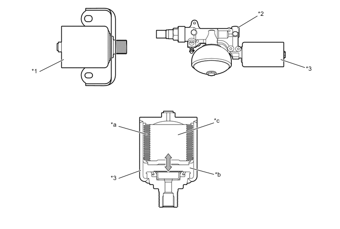
*1 Front Relief Gas Chamber *2 Rear Suspension Control Accumulator Assembly *3 Rear Relief Gas Chamber - - *a Metallic Bellows *b Fluid Chamber *c Gas Chamber (Nitrogen Gas) - - Specifications Relief Gas Chamber Front Rear Sealed Gas Nitrogen Gas ← Gas Chamber Volume 120 cc (7.3 cu in.) 150 cc (9.2 cu in.) Sealed Gas Pressure 13.5 MPa (138 kgf/cm2, 1958 psi)
10 MPa (102 kgf/cm2, 1450 psi)
-
-
Damping Force Control Actuator
-
The damping force control actuator is provided for each of the suspension control accumulator assemblies.
-
This actuator consists of the 16-step step motor, a screw mechanism (which converts the rotational movement to a linear movement), a spool valve, a soft damping force valve and a hard damping force valve.
-
Signals from the suspension control ECU activate the actuator, causing the spool valve to switch the fluid passage. Thus, the volume of fluid that passes through each valve is varied in order to control the damping force in 16 steps.
*1 Front Suspension Control Accumulator Assembly *2 Rear Suspension Control Accumulator Assembly *3 16-step Step Motor *4 Screw Mechanism *5 Spool Valve *6 Hard Damping Force Valve *7 Soft Damping Force Valve - - *a Damping Force Control Actuator Cross Section - - Figure 7. Fluid Flow in Damping Force Control Actuator
*a Damping Force (Soft) *b Damping Force (Medium) *c Damping Force (Hard) - -
-
-
Shock Absorber
-
The shock absorber has a dual construction using a high-pressure main seal made of fluoroethylene resin and a high-pressure oil seal made of nitrile rubber and provided with a backup ring in order to ensure sealing performance and reduce friction.
-
The piston size has been increased to improve response, drivability, and ride comfort.
Figure 8. Front Shock Absorber
*1 High-pressure Main Seal *2 High-pressure Oil Seal Figure 9. Rear Shock Absorber
*1 High-pressure Main Seal *2 High-pressure Oil Seal
-
-
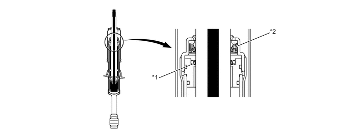
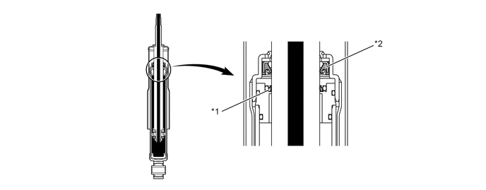
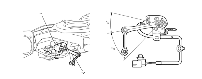
Height Control Sensor
-
Hall IC type height control sensors have been provided. The Hall IC converts the changes in the magnetic flux that occur at that time into electrical signals, and outputs them in the form of height control sensor effort to the suspension control ECU.
-
There are 2 front height control sensors, 1 for the right, and the other for the left. They are mounted via the control links to the upper arms of the front suspension and to the body.
-
There are also 2 rear height control sensors, 1 for the right, and the other for the left. They are mounted via the control links to the upper control arms of the rear suspension and to the body.
-
Through the use of a height control sensor link and shaft, each height control sensor converts the rectilinear movement of the control link into a rotational movement, and the result is detected in the form of a rotational angle.
Figure 10. Front Height Control Sensor
*1 Control Link *2 Front Height Control Sensor *3 Bound *4 Rebound Figure 11. Rear Height Control Sensor
*1 Rear Height Control Sensor *2 Control Link *3 Bound *4 Rebound
-
-
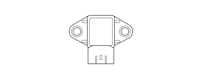
Acceleration Sensor
-
The acceleration sensors detect the vertical movement above the body.
-
The front acceleration sensors are placed on the right and left sides of the instrument panel and the rear acceleration sensor is placed inside the suspension control ECU. Thus, the acceleration sensors independently detect the vertical acceleration rate of the vehicle.
Figure 12. Front Acceleration Sensor
-
-
Yaw Rate Sensor and Deceleration Sensor
-
A yaw rate sensor and deceleration sensor are built into the airbag sensor assembly.
-
These sensors detects the yaw rate and lateral and longitudinal acceleration and deceleration, and sends this signal to the suspension control ECU.
-
-
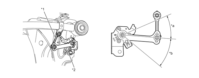
Steering Angle Sensor
-
A steering angle sensor is provided in the combination switch area. This sensor detects the amount of steering effort and the direction of steering wheel.
-
The sensor assembly contains two sets of magnetic reluctance elements that detect the rotational movement of a magnet that is built into the detection gear. Thus, the sensor detects the changes that occur in the magnetic reluctance elements along with the rotational movement of the detection gear, in order to detect the rotational movement of the steering wheel.
-
-
Drive Mode Select, Height Control Switch, Height Select Switch and Easy Access Mode Switch
-
The height select switch, height control switch and drive mode select are built into the integration control and panel assembly (console module switch), integrating them on the console and allowing the driver to keep his/her driving posture when using those traction and drive related switches.
-
The easy access mode switch is built into the combination switch assembly.
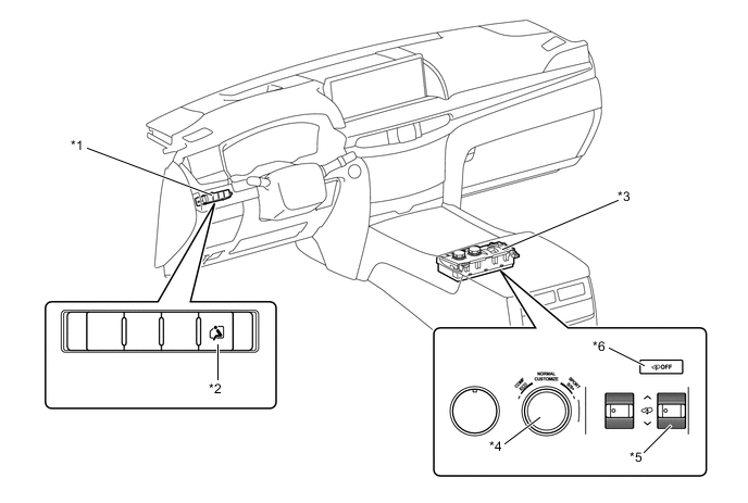
*1 Combination Switch Assembly *2 Easy Access Mode Switch *3 Integration Control and Panel Assembly *4 Drive Mode Select *5 Height Select Switch *6 Height Control Switch Switch Function Integration Control and Panel Assembly Height Select Switch
-
Selects vehicle height between three levels by operating this switch.
-
When the height control switch is on, vehicle height cannot be changed.
Height Control Switch Prohibits the vehicle height control by operating this switch. Drive Mode Select Selects damping force between 3 levels by operating this switch. Combination Switch Assembly Easy Access Mode Switch Switches the easy access control between on and off by operating this switch. -
-
-
-
System Operation
-
Vehicle Height Control
-
The vehicle height control controls the vehicle height over 5 levels in accordance with the manual switch operation or the driving conditions.
-
The vehicle height control has the following functions:
Function Outline Vehicle Height Selection Function Enables the selection of 3 levels of vehicle height by operating a switch. Automatic Leveling Function This function maintains the vehicle height constant regardless of the load conditions such as the number of occupants or the weight of the cargo under the prescribed loading condition. It effects constant control so that the vehicle height is maintained at a prescribed value when the Normal position is selected. Extra HI Mode
-
While driving on an unpaved road with the transfer shifted in the L4 range and the vehicle height set to the HI position, if one of the wheels freewheels, the vehicle is raised up to the Extra HI position, 20 mm (0.8 in.) higher than the HI position.
-
When the CRAWL function of the brake control system is in operation and the vehicle height adjustment request signal for switching to the Extra HI position is input from the skid control ECU to the suspension control ECU, the vehicle is raised up to the Extra HI position.
Vehicle Speed Sensing Function The vehicle height will be automatically adjusted in accordance with the vehicle speed and selected vehicle height. Easy Access Control For convenient in-and-out access, this function effects vehicle height control in conjunction with the engine switch when the easy access mode is set to om. Vehicle Height Adjustment Prohibition Control When the vehicle is raised on a jack or is being towed, the vehicle adjustment can be prohibited by operating the height control switch*. However, the prohibition control cancels automatically when the vehicle speed becomes higher than approximately 80 km/h (50 mph) at the Normal position, or higher than approximately 30 km/h (19 mph) at the HI or LO position. *: This control is available only when the vehicle is stopped [the vehicle speed is 5 km/h (3.1 mph) or less].
-
-
Vehicle Height Selection Function
-
The following 3 types of vehicle heights can be selected by operating the switch: normal vehicle height (Normal), low vehicle height (LO), and high vehicle height (HI).
Selected Height Position LO Normal HI Vehicle Height Front Approximately
-60 mm (-2.4 in.)
Standard Vehicle Height Approximately
+50 mm (+2.0 in.)
Rear Approximately
-40 mm (-1.6 in.)
Standard Vehicle Height Approximately
+60 mm (+2.4 in.)
Vehicle Height Adjustment Speed*1 Up LO to Normal Approximately 11 to 16 seconds Down Normal to LO Approximately 2 seconds*2 *1: Vehicle height control speed differs depending on the loaded condition.
*2: Approximately 5 seconds when the shift lever is in N.
Tech Tips
When a load exceeding the following axle weight limitations is applied to the vehicle, it causes the vehicle not to stay at the Normal height. At times like this, it might not be possible to raise the vehicle height even by operating the switch.
-
In Normal mode: Front axle weight: 1460 kg (3212 lb)/ Rear axle weight: 1800 kg (3960 lb)
-
-
Raising Vehicle Height (Manual Operation)
-
When the height select switch is operated to raise the vehicle height, the suspension control ECU opens the leveling valves for each of the wheels arranged inside the height control valve. This allows the fluid to flow from the pump into the shock absorber and gas chamber and results in an increase in the vehicle height. Simultaneously, the accumulator valve opens, guiding the fluid into them from the suspension control pump accumulator, thereby raising the vehicle height.
*1 Height Control Pump and Motor *2 Suspension Control Pump Accumulator *3 Front Suspension Control Accumulator Assembly *4 Front Shock Absorber RH *5 Height Control Valve *6 Front Suspension Control Valve Assembly *7 Relief Gas Chamber *8 Rear Suspension Control Accumulator Assembly *9 Center Suspension Control Cylinder *10 Rear Shock Absorber RH *a To Front Shock Absorber LH *b To Rear Shock Absorber LH -
Lowering Vehicle Height (Manual Operation)
-
When the height select switch is operated to lower the vehicle height from the HI to the Normal position, or from the Normal to the LO position, the suspension control ECU opens the front and rear leveling valves. As a result, the fluid in the gas chambers and the shock absorbers arranged for each of the wheels returns into the reservoir tank, thereby lowering the height of the suspension. However, if the rear side is expected to become lower more quickly due to the load condition, and the difference between the lowering of the front side and the rear side becomes greater than a prescribed value, the rear leveling valve closes once, allowing only the vehicle height to become lowered at the front side. This feature prevents the headlights from being aimed upward.

*1 Height Control Pump and Motor *2 Suspension Control Pump Accumulator *3 Front Suspension Control Accumulator Assembly *4 Front Shock Absorber RH *5 Height Control Valve *6 Front Suspension Control Valve Assembly *7 Relief Gas Chamber *8 Rear Suspension Control Accumulator Assembly *9 Center Suspension Control Cylinder *10 Rear Shock Absorber RH *a To Front Shock Absorber LH *b To Rear Shock Absorber LH -
Fluid Stored in Height Control Accumulator
-
Normally, the suspension control pump accumulator stores only the amount of fluid that is equivalent that used in raising the vehicle height once. Therefore, after the vehicle has been raised from the LO position to the Normal position, or from the Normal position to the HI position, it is necessary to replenish the fluid in the suspension control pump accumulator.
-
At this time, the pump motor is operated to rotate the pump, the leveling valves are closed, the accumulator valve of the height control valve is opened, and the fluid is stored in the suspension control pump accumulator.
-
When the vehicle height is raised while the fluid that is stored in the suspension control pump accumulator has not reached a prescribed pressure, only the fluid that is discharged by the pump is used for raising the vehicle height, without using the fluid in the suspension control pump accumulator.
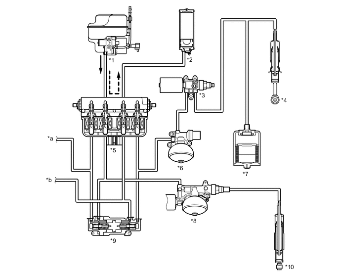
*1 Height Control Pump and Motor *2 Suspension Control Pump Accumulator *3 Front Suspension Control Accumulator Assembly *4 Front Shock Absorber RH *5 Height Control Valve *6 Front Suspension Control Valve Assembly *7 Relief Gas Chamber *8 Rear Suspension Control Accumulator Assembly *9 Center Suspension Control Cylinder *10 Rear Shock Absorber RH *a To Front Shock Absorber LH *b To Rear Shock Absorber LH
-
-
Vehicle Speed Sensing Function
-
This function automatically adjusts the vehicle to any of the six levels of the height positions depending on vehicle speeds and vehicle conditions. The values of each height position are as follows:
Height Position Front Suspension Adjustment Value Rear Suspension Adjustment Value Extra HI 70 mm (2.8 in.) 80 mm (3.1 in.) HI 50 mm (2.0 in.) 60 mm (2.4 in.) L4 Range HI 25 mm (1.0 in.) 25 mm (1.0 in.) Normal 0 mm (0 in.) 0 mm (0 in.) High Speed LO -20 mm (-0.8 in.) -15 mm (-0.6 in.) LO -60 mm (-2.4 in.) -40 mm (-1.6 in.) -
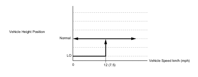
If the vehicle speed exceeds approximately 12 km/h (7.5 mph) when the vehicle height is set to the LO position, the vehicle height will be automatically adjusted to the Normal position.
-
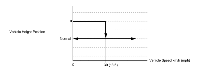
If the vehicle speed exceeds approximately 30 km/h (18.6 mph) when the vehicle height is set to the HI position, the vehicle height will be automatically adjusted to the Normal position.
-
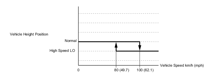
If the vehicle speed exceeds approximately 100 km/h (62.1 mph) when the vehicle height is set to the Normal position, the vehicle height will be adjusted to the High Speed LO position. If the vehicle speed is decreased to approximately 80 km/h (49.7 mph) or less while this is in effect, the vehicle height will be automatically adjusted to the Normal position.
-
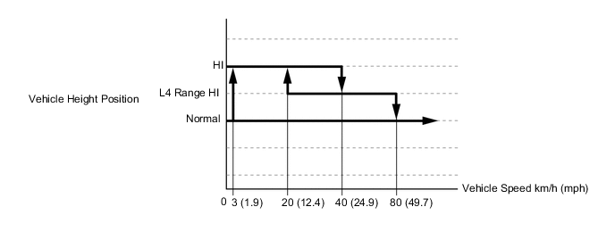
When the transfer is set in the L4 range, the following control is performed.
-
If the vehicle speed exceeds approximately 3 km/h (1.9 mph) when the vehicle height is set to the Normal or LO position and a rough road condition is detected, the vehicle height will be automatically adjusted to the HI position.
-
When the vehicle speed exceeds 50 km/h (31.1 mph), the vehicle height will be adjusted to the L4 Range HI position. If the vehicle further accelerates in this condition and the vehicle speed exceeds 80 km/h (49.7 mph), the vehicle height will be automatically adjusted to the Normal position. On the other hand, if the vehicle decelerates and the vehicle speed is decreased to 20 km/h (12.4 mph) or less, the vehicle height will be automatically adjusted to the HI position.
-
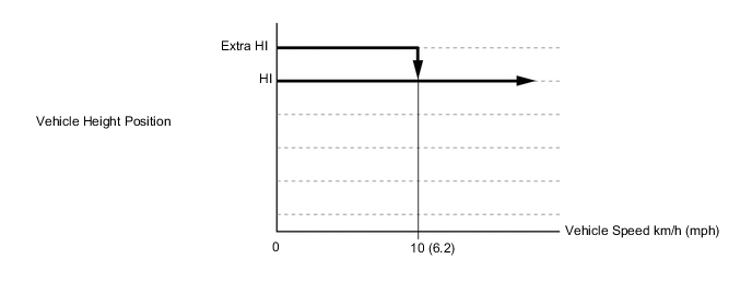
If the vehicle speed exceeds approximately 10 km/h (6.2 mph) when the vehicle height is set to Extra HI position, the vehicle height will be automatically adjusted to the HI position.
-
-
Easy Access Control
-
This function effects vehicle height control in conjunction with the engine switch when all of the following conditions have been met.
Condition Function
-
Easy access mode switch is on
-
Vehicle height is Normal
-
Shift lever is P
-
Vehicle speed is 0 km/h (0 mph)
-
Vehicle is on flat road
-
Any door (including back door) is not opened after stopping vehicle
-
Engine switch is turned OFF within approx. 30 seconds after stopping vehicle
-
The vehicle height is changed from the Normal position to the LO position.
-
The wireless door lock buzzer sounds*1.
-
The hazard light flashes*2.
-
The easy access mode indicator light is changed from illuminating condition to blinking condition.
-
Easy access mode switch is on
-
Vehicle speed is 12 km/h (7.5 mph) or more
-
Engine switch is turned ON (IG)
-
The vehicle height is changed from the LO position to the Normal position.
Tech Tips
*1: Except China Models
*2: For China Models
*1 Normal Position *2 LO Position -
-
-
-
Damping Force Control
-
The damping force control has following functions:
Control Function Non-linear H∞ Control Smoothly changes the damping force to a target value in accordance with the changes in the road surface or driving conditions. Thus, excellent ride comfort has been realized while a high level of vibration damping performance is ensured. Thumping Sensitive Control Controls the shock absorbers so that the damping force for the shock absorbers will not increase while driving on a rough road. Large-amplitude Control When the suspension control ECU detects any large fluctuation in the wheel stroke when driving at low speeds, the damping force is adjusted to a firmer variable range for a predetermined time, to decrease the spring vibration. Roll Posture Control Changes the damping force to control the vehicle posture during cornering. As a result, excellent stability and controllability have been realized during cornering. Anti-dive Control During braking, this function makes the damping force firmer to restrain the body dive, thus ensuring excellent stability and controllability. Anti-squat Control During acceleration, this function makes the damping force firmer to minimize the changes in the vehicle body posture. High Speed Control
-
This function varies the variable range of the damping force according to vehicle speed in order to realize a soft and comfortable ride and a stable driving condition.
-
The damping force is controlled in a softer variable range at low speeds, and in a firmer variable range at high speeds.
Absorber Control The drive mode select enables the driver to select a desired damping force from the 3 modes. L4 Range Control The damping force is normally controlled in 16 steps. However, when the transfer is set in the L4 range, it is controlled in the intermediate 8 steps*, thereby ensuring riding comfort during off-road driving. *: It is controlled in 3 steps when the vehicle speed is 55 km/h (34.2 mph) or less, and 8 steps when the vehicle speed is more than 55 km/h (34.2 mph).
-
-
Non-linear H∞ Control
-
This control uses 3 acceleration sensors to detect the vertical acceleration rate that corresponds to the bumps on the road surface and applies the non-linear H∞ control to calculate the target damping force.
-
Unlike linear control which linearly changes the damping force proportional to the sprung acceleration rate, non-linear H∞ control achieves a higher level of vibration damping performance. As a result, superior riding comfort is ensured on any road surface or under any driving conditions.

-
The non-linear H∞ control has been optimized for off-road SUVs and the control and operation range has been expanded. Aftershocks when running rough roads have been reduced through the optimally tuned control in the transfer L4 mode, which lessens the driver's stress through the stabilized eye level, as well as secures the tire's road holding performance, resulting in the improved driving performance in rough roads.
-
-
Roll Posture Control
-
This control changes the damping force to control the vehicle posture during cornering. As a result, excellent stability and controllability have been realized during cornering. This control assumes that two types of shock absorbers (one for restraining roll and the other for restraining lift) are provided at an imaginary point on the inside of the turn of the vehicle. The function of these shock absorbers is to prevent the center of gravity of the vehicle from rising. The damping force of the front and rear shock absorbers is controlled in order to control the vehicle's posture as in this imaginary condition.
-
To effect this control, the suspension stroke information is calculated based on the information from the 3 acceleration sensors and a steering angle sensor. Thus, the driving conditions of the vehicle are detected.
*1 for Restraining Lift *2 Center of Gravity
-
-
-
Spring Rate Control
-
The front shock absorber includes No. 1 and No. 2 gas chambers. These gas chambers are automatically selected in accordance with the driving conditions, and this ensures both driving comfort and steering stability.
-
Under normal driving conditions, the suspension control ECU opens the spring rate switching valve and allows the gas chambers to operate, thereby reducing the spring rate and ensuring ride comfort.
-
If the vehicle speed exceeds a predetermined speed while cornering or when the brake pedal is depressed, the suspension control ECU closes the spring rate switching valve and allows only the No. 2 gas chamber to operate, thereby increasing the spring rate to control the vehicle posture and improve the steering stability.
Figure 13. Normal Driving Condition
*1 No. 1 Gas Chamber *2 Spring Rate Switching Valve (Open) *3 Front Shock Absorber *4 Relief Gas Chamber *5 No. 2 Gas Chamber - - Figure 14. During Cornering or while Brake Pedal is being Depressed
*1 No. 1 Gas Chamber *2 Spring Rate Switching Valve (Closed) *3 Front Shock Absorber *4 Relief Gas Chamber *5 No. 2 Gas Chamber - -
-
-
4-wheel Related Control
-
General
-
When a hydraulic pressure of one of the shock absorbers has changed because of changes in driving conditions, the 4-wheel related control adjusts the hydraulic pressure for the other shock absorbers through the center suspension control cylinder which is connected to all shock absorbers to stabilize the vehicle posture. When the vehicle is cornering, braking or driving on rough roads, the center suspension control cylinder operates differently through the center suspension control cylinder structure and shock absorber connection method, thereby achieving the optimum on-road and off-road driving performance.
-
-
Driving under Rough Road Conditions (When an impact force is applied to only one wheel)
-
When an impact is only applied to the front right wheel during on-road driving, the piston placed inside the center suspension control cylinder moves to the left in accordance with increase in the wheel pressure. This movement prompts the other shock absorbers to expand or contract as shown in the illustration, thereby improving the grounding performance.
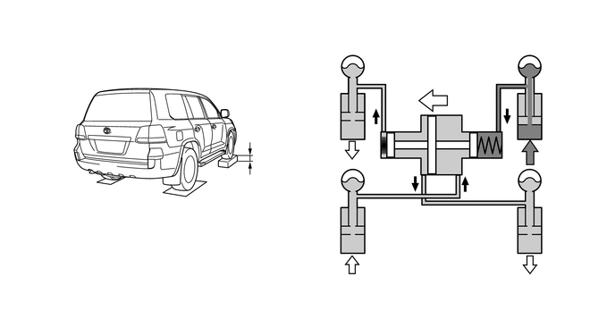
-
-
While Cornering
-
As shown in the illustration, when a small load is applied to the rear of the vehicle and the rolling stiffness of the suspension for the front wheels is high, the hydraulic pressure of the front right absorber is high. Then, the piston inside the center suspension control cylinder moves to the left in accordance with changes in the hydraulic pressure balance for each of the wheels. As a result, the pressure is applied to the rear right absorber, and the rear suspension is caused to move in the opposite direction from that of the front suspension.
-
On the other hand, when a large load is applied to the rear of the vehicle and the rolling stiffness of the suspension for the rear wheels is high, the hydraulic pressure of the rear right absorber is high. Then, the piston inside the center suspension control cylinder moves to the right in accordance with changes in the hydraulic pressure balance for each of the wheels. This optimizes the rolling stiffness distribution regardless of load quantity and improves the steering stability.
Figure 15. When Cornering Left (Front wheel rolling stiffness is high)

Figure 16. When Cornering Left (Rear wheel rolling stiffness is high)

-
-
-
-
Fail-safe
-
If the suspension control ECU detects a malfunction in the active height control suspension system, the ECU illuminates the master warning light, indicates the warning message on the multi-information display, and sounds the buzzer to inform the driver of the malfunction.
-
When a vehicle can still be driven even if a system malfunction occurs, the vehicle height is automatically returned to the Normal position at a speed of 30 km/h (19 mph) or more.
-
-
Diagnosis
-
If a system malfunction occurs, Diagnostic Trouble Code (DTC) is stored in memory of the suspension control ECU. The DTC can be read by connecting a Global TechStream (GTS). For details,refer to the Repair Manual.
-
-
Active Test
-
Vehicle height control and damping force control operation in the suspension system can be checked by connecting a Global TechStream (GTS). For details, refer to the Repair Manual.
-