TRANSFER
-
GENERAL
-
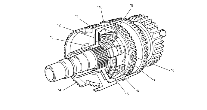
The construction of the JF2A transfer is shown below.
-
A planetary gear unit is used in the reduction mechanism and a silent chain is used to reduce front drive noise.
-
The center differential uses a TORSEN LSD (Limited Slip Differential). As a result, this LSD ensures the proper torque distribution during acceleration and high-speed driving.
-
A lever type synchromesh mechanism is used for the H4-L4 switching section to eliminate gear clash when switching between H4 and L4.
-
For the JF2A transfer, a transfer shift actuator that has 2 built-in shift motors is used. As a result, switching between H4 and L4 can be performed independently using the shift motors, achieving a simple shift actuation mechanism. This enhances efficiency of power transfer and durability of the shift mechanism.
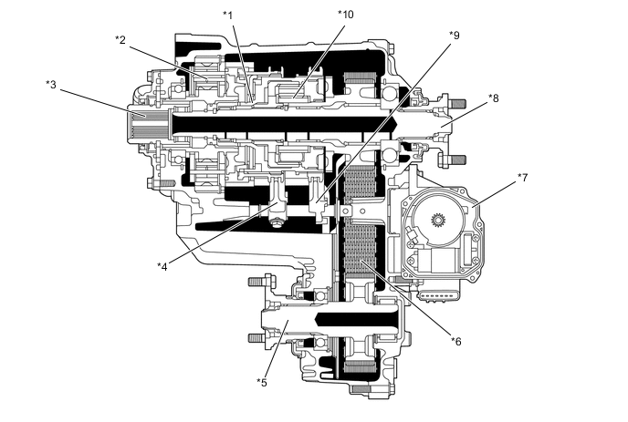
*1 Lever Type Synchromesh Mechanism *2 Transfer Low Planetary Gear *3 Transfer Input Shaft *4 Transfer Gear Shift Fork No. 2 *5 Front Transfer Output Shaft *6 Silent Chain *7 Transfer Shift Actuator *8 Rear Transfer Output Shaft *9 Transfer Gear Shift Fork No. 1 *10 Center Differential
-
-
-
PLANETARY GEAR UNIT
-
General
-
The transfer low planetary gear unit consists of a transfer low planetary sun gear, 6 transfer low planetary pinion gears, a transfer low planetary ring gear, and a transfer low planetary carrier.
-
The transfer low planetary sun gear is integrated with the transfer input shaft.
-
The 6 transfer low planetary pinion gears are fitted to the transfer low planetary carrier. Each transfer low pinion gear shaft is fixed to the transfer low planetary carrier. A planetary spline piece is fitted to the rear of the transfer low planetary carrier.
-
The transfer low planetary ring gear is fixed to the transfer case and its internal teeth mesh with the transfer low planetary pinion gears.
-
In this planetary gear unit, the drive torque transmission route is switched in accordance with the movement of the transfer high and low clutch sleeve. The drive torque from the transfer input shaft is transmitted to the differential case via the transfer high and low clutch sleeve.
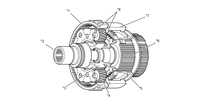
*1 Transfer Low Planetary Ring Gear *2 Transfer Input Shaft *3 Transfer Low Planetary Sun Gear *4 Transfer Low Planetary Pinion Gear *5 Transfer High and Low Clutch Sleeve *6 Differential Case *7 Planetary Spline Piece *8 Transfer Low Planetary Carrier -
-
-
H4 Position
-
In the H (H4) position, the splines at the rear of the transfer input shaft mesh with the internal gear teeth of the transfer high and low clutch sleeve.
-
Also, the transfer high and low clutch sleeve is meshed to the differential case. Thus, the rotation of the input shaft is transmitted to the transfer high and low clutch sleeve, and then to the differential case.
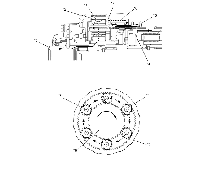
*1 Transfer Low Planetary Pinion Gear *2 Transfer Low Planetary Ring Gear *3 Transfer Input Shaft *4 Differential Case *5 Transfer High and Low Clutch Sleeve *6 Planetary Spline Piece *7 Transfer Low Planetary Carrier *8 Transfer Low Planetary Sun Gear
-
-
L4 Position
-
In the L (L4) position, the external teeth of the transfer high and low clutch sleeve are meshed with the planetary spline piece.
-
Thus, the rotation of the transfer input shaft is transmitted in a reduced form to the transfer low planetary sun gear, transfer low planetary pinion gears, transfer low planetary pinion gear shafts, transfer low planetary carrier, planetary spline piece, transfer high and low clutch sleeve, and differential case.
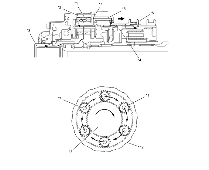
*1 Transfer Low Planetary Pinion Gear *2 Transfer Low Planetary Ring Gear *3 Transfer Input Shaft *4 Differential Case *5 Transfer High and Low Clutch Sleeve *6 Planetary Spline Piece *7 Transfer Low Planetary Carrier *8 Transfer Low Planetary Sun Gear
-
-
-
CENTER DIFFERENTIAL (TORSEN LSD)
-
General
-
The center differential uses a TORSEN LSD (Limited Slip Differential).
-
The TORSEN LSD is torque-sensing LSD. It generates a limited-differential torque in proportion to the drive torque, and instantly changes the front and rear torque distribution.
-
The torque distribution during straightline driving is 40/60 (front/rear), which is helpful for an appropriate steering response during the initial stage of a turn. During the acceleration stage of a turn, the torque distribution to the rear wheels increases.
-
This center differential consists of a differential case, a ring gear coupling, a ring gear, 8 pinion gears, a sun gear, a planetary carrier, and clutch plates.
*1 Ring Gear *2 No. 1 Clutch Plate *3 Ring Gear Coupling *4 Differential Case *5 No. 3 Clutch Plate *6 No. 2 Clutch Plate *7 Planetary Carrier *8 No. 4 Clutch Plate *9 Pinion Gear *10 Sun Gear 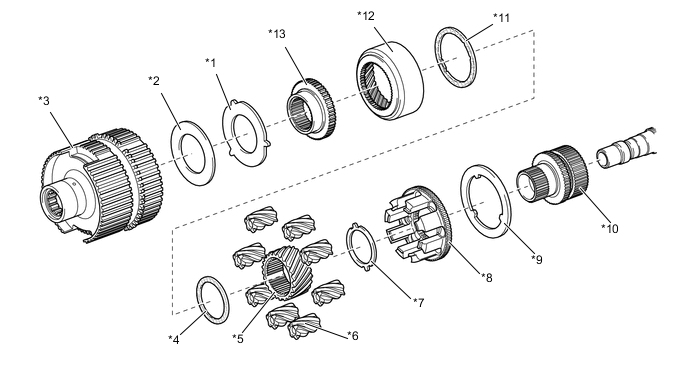
*1 No. 1 Clutch Plate *2 Shim *3 Differential Case *4 No. 3 Clutch Plate *5 Sun Gear *6 Pinion Gear *7 No. 4 Clutch Plate *8 Planetary Carrier *9 Carrier Nut *10 Sun Gear Coupling *11 No. 2 Clutch Plate *12 Ring Gear *13 Ring Gear Coupling - - Tech Tips
The TORSEN LSD cannot be disassembled, so it must be replaced as an assembly. For details, see the Repair Manual.
-
-
Normal Driving Operation
-
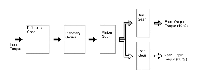
During normal driving (front wheel speed = rear wheel speed), the drive torque that is input by the differential case is transmitted (front: 40/rear: 60) as shown below, without involving the LSD function.
*1 Ring Gear *2 Differential Case *3 Sun Gear *4 Planetary Carrier *5 Pinion Gear - - *a Input Torque *b Rear Output Torque *c Front Output Torque - - Figure 1. Power Flow
-
-
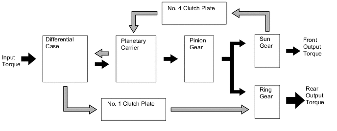
Front Wheel Skid Driving Operation
-
During front wheel skid driving (front wheel speed > rear wheel speed) when a rotational difference exists between the sun gear and the ring gear, the distribution of the drive torque that is input by the differential case changes instantly before the torque is transmitted, as follows:
-
The sun gear transmits torque to the planetary carrier while pushing on the No. 4 clutch plate. The planetary carrier transmits this torque to the ring gear from the differential case via the No. 1 clutch plate.
-
The ring gear outputs torque while pushing on the No. 1. clutch plate.
-
These LSD functions change the torque distribution.
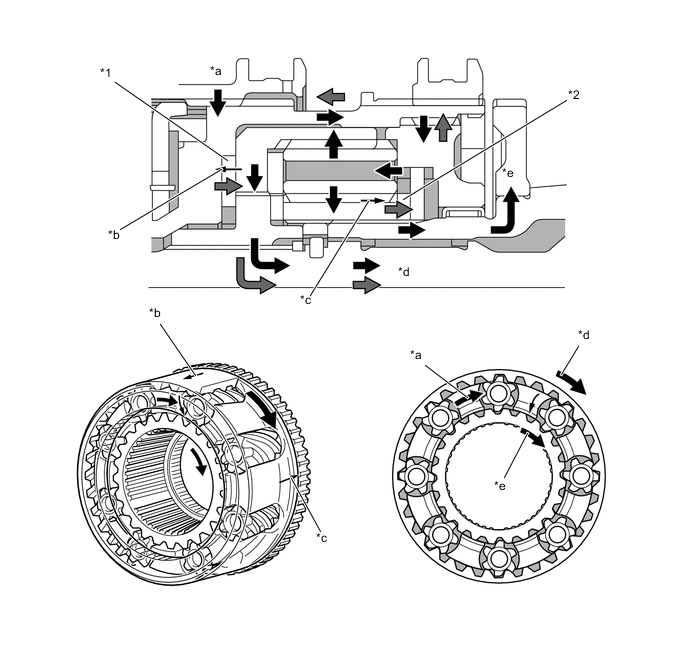
*1 No. 1 Clutch Plate *2 No. 4 Clutch Plate *a Input Torque *b Pushing on the No. 1 Clutch plate *c Pushing on the No. 4 Clutch plate *d Rear Output Torque *e Front Output Torque - - Figure 2. Power Flow
-
-
-
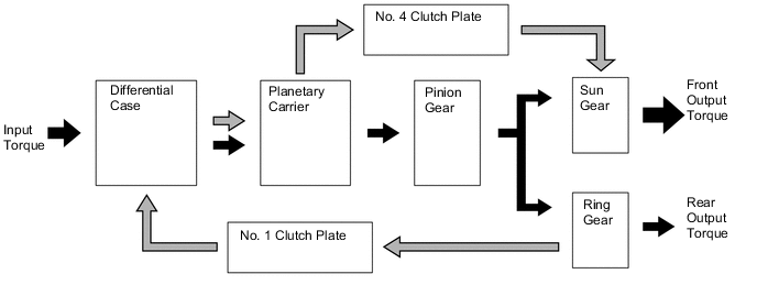
Rear Wheel Skid Driving Operation
-
During rear wheel skid driving (front wheel speed < rear wheel speed), when a rotational difference exists between the sun gear and the ring gear, the distribution of the drive torque that is input by the differential case changes instantly before the torque is transmitted, as follows:
-
The ring gear transmits torque to the differential case while pushing the No. 1 clutch plate. The differential case transmits this torque from the planetary carrier to the sun gear via the No. 4 clutch plate.
-
The sun gear outputs torque while pushing on the No. 4. clutch plate.
-
These LSD functions change the torque distribution.
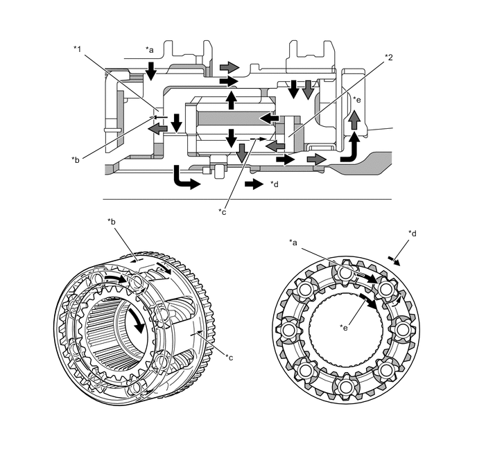
*1 No. 1 Clutch Plate *2 No. 4 Clutch Plate *a Input Torque *b Pushing on the No. 1 Clutch plate *c Pushing on the No. 4 Clutch plate *d Rear Output Torque *e Front Output Torque - - Figure 3. Power Flow
-
-
-
-
TRANSFER SHIFT ACTUATOR
-
General
-
The transfer shift actuator consists of the following two mechanisms.
-
H4-L4 switching (to switch the transfer gear ratio)
-
Free-lock switching (to switch the center differential lock)
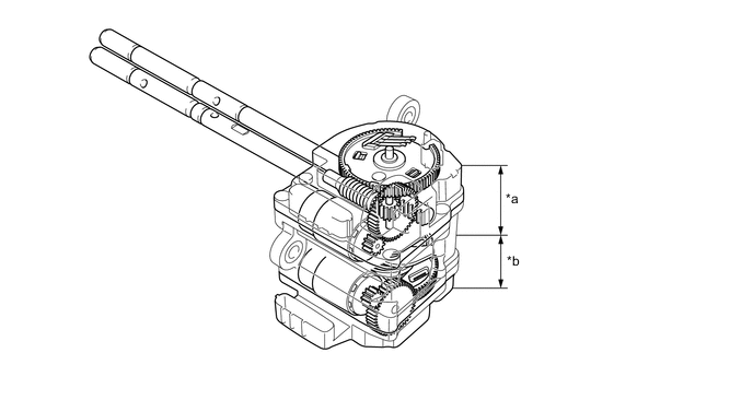
*a Drive Mechanism (For Free-Lock Switching) *b Drive Mechanism (For H4-L4 Switching) -
-
-
Drive Mechanism for H4-L4 Switching
-
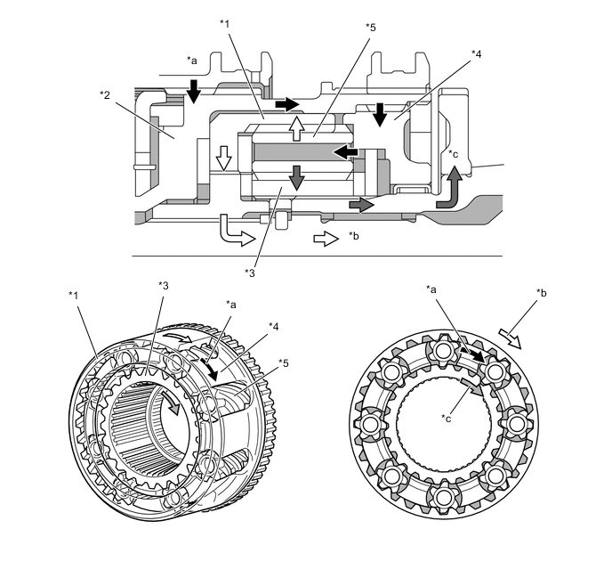
The drive mechanism for H4-L4 switching consists of an H-L shift motor, a limit switch, a transfer neutral position switch, a wait mechanism (spiral spring), and an H-L shift fork shaft. This drive mechanism cannot be disassembled.
-
The limit switch has three contact points and detects the shift motor position.
-
The wait mechanism (spiral spring) is used for H-L shift fork shaft operations. If the operating resistance of the H-L shift fork shaft is high, the rotation of the H-L shift motor is partially stored in the spiral spring. Afterward, when the operating resistance is reduced, the spring force causes the H-L shift fork shaft to slide.
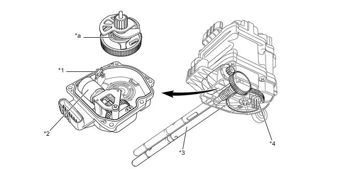
*1 Transfer Neutral Position Switch *2 H-L Shift Motor *3 H-L Shift Fork Shaft *4 Limit Switch (HL1, HL2, HL3) *a Wait Mechanism (Spiral Spring) - - Figure 4. Combination of 3 Contact Point Switches
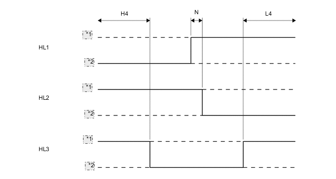
*1 OFF *2 ON
-
-
Drive Mechanism for Free-Lock Switching
-
The drive mechanism for free-lock switching consists of a center differential lock shift motor, a limit switch, a center differential lock position switch, a wait mechanism (spiral spring), a center differential lock shift fork shaft, and an actuator temperature sensor*. This drive mechanism cannot be disassembled.
-
The limit switch has three contact points and detects the shift motor position.
-
The wait mechanism (spiral spring) is used for center differential lock shift fork shaft operations. If the operating resistance of the center differential lock shift fork shaft is high, the rotation of the center differential lock shift motor is partially stored in the spiral spring. Afterward, when the operating resistance is reduced, the spring force causes the center differential lock shift fork shaft to slide.
-
An actuator temperature sensor is provided on the shift actuator in order to allow an increase of the amount of current applied to the shift motors, and improves switching performance at low temperatures.*
-
*: Models for Russia, Kazakhstan and China
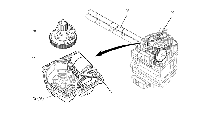
*A Models for Russia, Kazakhstan and China - - *1 Center Diff. Lock Position Switch *2 Actuator Temperature Sensor *3 Center Diff. Lock Shift Motor *4 Limit Switch (TL1, TL2, TL3) *5 Center Diff. Lock Shift Fork Shaft - - *a Wait Mechanism (Spiral Spring) - - Figure 5. Combination of 3 Contact Point Switches
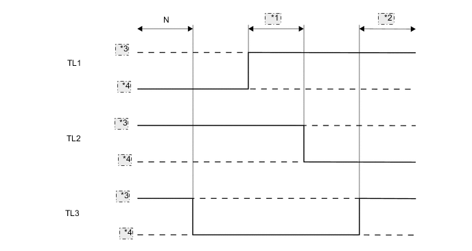
*1 Free *2 Lock *3 OFF *4 ON -
-
-