LIGHTING
-
General
-
The illuminated entry system is used.
-
The door trim illumination has been newly provided.
-
The front interior light, No. 1 room light and No. 2 room light are operated when the light switch is in the DOOR position.
-
The illuminated entry system controls the front foot lights and door trim illuminations.
-
-
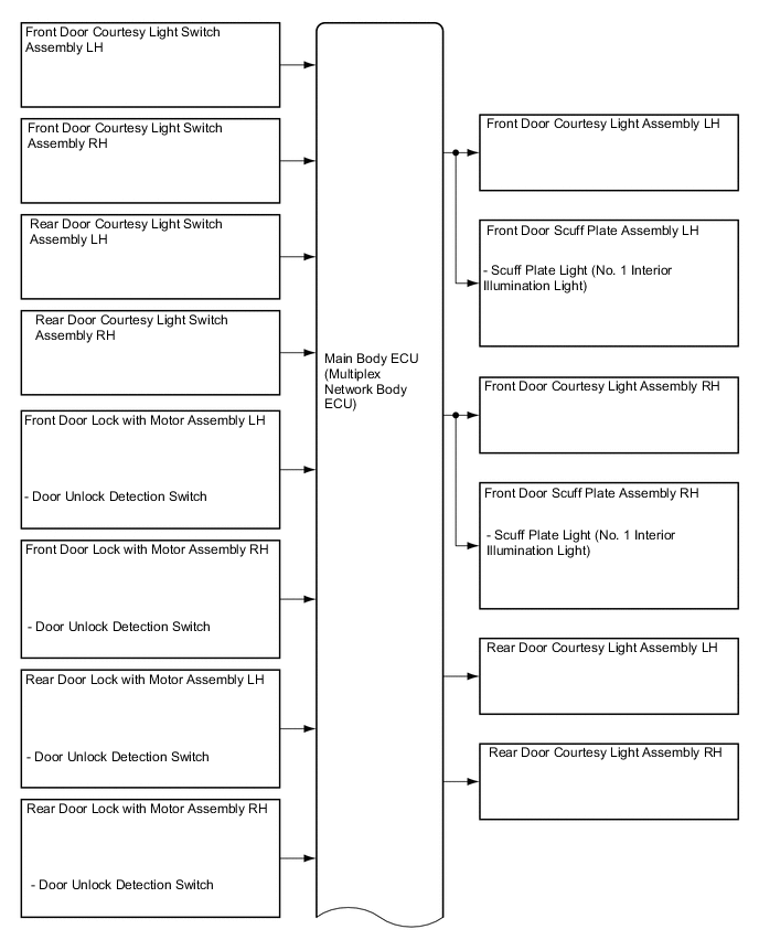
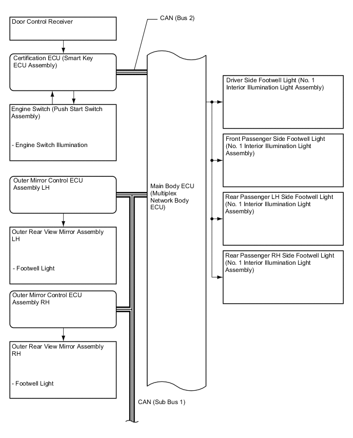
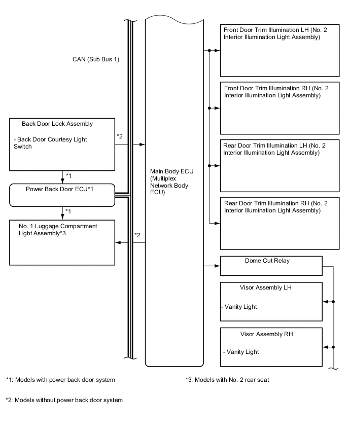
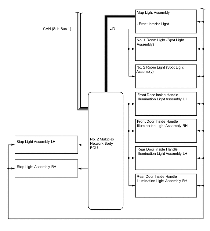
System Diagram
-
Layout of Main Components
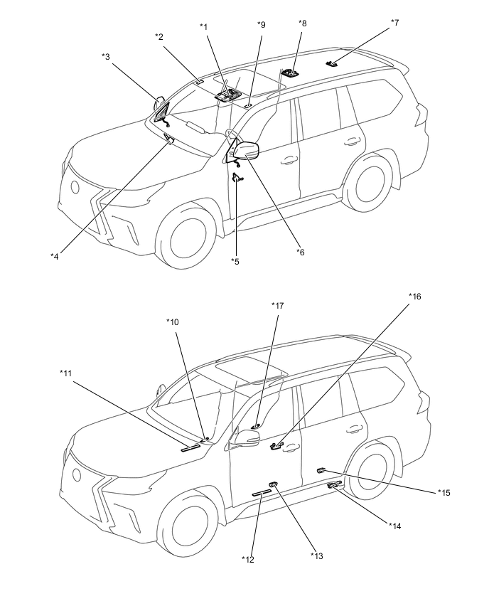
*1 Map Light Assembly *2 Visor Assembly RH (Vanity Light) *3 Outer Rear View Mirror Assembly RH
-
Footwell Light
*4 Outer Mirror Control ECU Assembly RH *5 Outer Mirror Control ECU Assembly LH *6 Outer Rear View Mirror Assembly LH
-
Footwell Light
*7 No. 2 Room Light *8 No. 1 Room Light *9 Visor Assembly LH (Vanity Light) *10 Front Door Courtesy Light Assembly RH *11 Front Door Scuff Plate Assembly RH (Scuff Plate Light) *12 Front Door Scuff Plate Assembly LH (Scuff Plate Light) *13 Front Door Courtesy Light Assembly LH *14 Step Light Assembly LH *15 Rear Door Courtesy Light Assembly LH *16 Step Light Assembly RH *17 Rear Door Courtesy Light Assembly RH - - 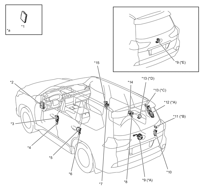
*A Models with Power Back Door System *B Models with No. 2 Rear Seat *C Models without Tire Pressure Warning System *D Models with Tire Pressure Warning System *E Models without Power Back Door System - - *1 Certification ECU (Smart Key ECU Assembly) *2 Main Body ECU (Multiplex Network Body ECU) *3 Front Door Lock with Motor Assembly LH *4 Front Door Courtesy Light Switch Assembly LH *5 Rear Door Lock with Motor Assembly LH *6 Rear Door Courtesy Light Switch Assembly LH *7 Front Door Courtesy Light Switch Assembly RH *8 Rear Door Courtesy Light Switch Assembly RH *9 Back Door Lock Assembly *10 No. 2 Multiplex Network Body ECU *11 No. 1 Luggage Compartment Light Assembly *12 Power Back Door ECU *13 Door Control Receiver *14 Rear Door Lock with Motor Assembly RH *15 Front Door Lock with Motor Assembly RH - - *a Refer to the Service Bulletin for the installation position of the parts. - - 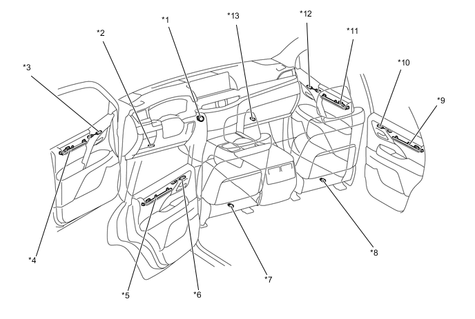
*1 Engine Switch (Push Start Switch Assembly) *2 Driver Side Footwell Light *3 Front Door Inside Handle Illumination Light Assembly LH *4 Front Door Trim Illumination LH *5 Rear Door Trim Illumination LH *6 Rear Door Inside Handle Illumination Light Assembly LH *7 Rear Passenger LH Side Footwell Light *8 Rear Passenger RH Side Footwell Light *9 Rear Door Trim Illumination RH *10 Rear Door Inside Handle Illumination Light Assembly RH *11 Front Door Trim Illumination RH *12 Front Door Inside Handle Illumination Light Assembly RH *13 Front Passenger Side Footwell Light - - -
-
Interior Light Control
-
Interior Light Control Function
-
The interior light control (front/ rear room lights and engine switch illumination) consists primarily of the fade-in/fade-out function and timer illumination function.
-
The interior light control activates as described in the diagram below when one of items is in the respective state.
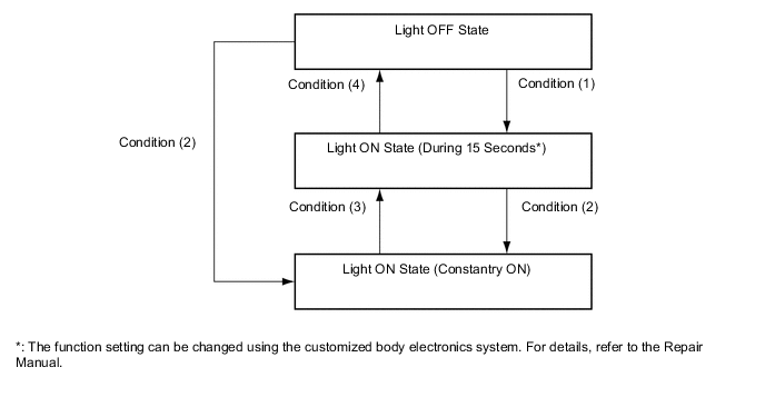
Condition Item Condition (1)
-
With engine switch OFF and all doors closed, key enters any actuation area around the doors.
-
Engine switch OFF and all doors closed, any door is unlocked.
-
Engine switch is turned from ACC, IG to OFF.
Condition (2)
-
Driver door or front passenger door is opened.
-
Rear passenger door is opened.
Condition (3)
-
Driver door or front passenger door is closed.
-
Rear passenger door is closed.
Condition (4)
-
More than approximately 15 seconds have elapsed since the light ON state (15 seconds duration)*.
-
All doors are closed, and are locked.
-
Engine switch is turned from OFF to ACC, IG.
-
Key is outside of all actuation area around the doors.
*: The function setting can be changed using the customized body electronics system. For details, refer to the Repair Manual.
-
-
-
Interior Footwell Light and Door Trim Illumination Light Control Function
-
The interior footwell light and door trim illumination light control consists primarily of the fade-in/fade-out function and timer illumination function.
-
The interior footwell light and door trim illumination light control operates as described in the diagram below when any one of the items for each condition is satisfied.
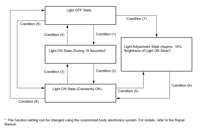
Condition Item Condition (1) With engine switch OFF and all doors closed, any door is unlocked. Condition (2)
-
Any door is open.
-
With shift lever at P position, engine switch is changed from OFF to IG.
Condition (3)
-
With engine switch ACC or OFF, all doors are closed.
-
With all doors closed, engine switch is changed from IG to OFF.
Condition (4)
-
More than 15 seconds have elapsed in the light ON state (15 seconds duration)*.
-
With engine switch OFF and all doors closed, all doors are locked.
Condition (5) Shift lever is put into other than P position with engine switch IG. Condition (6) With engine switch IG, shift lever is put into P position or any door is opened with shift lever in any position except P. Condition (7) With shift lever in other than P position, engine switch is changed from OFF to IG. Condition (8) With engine switch OFF and all doors locked, all doors are closed. Condition (9)
-
Any door is open.
-
With shift lever in P position, engine switch is changed from OFF to ON (IG).
*: The function setting can be changed using the customized body electronics system. For details, refer to the Repair Manual.
-
-
-
Side Step Light Control Function
-
The side step light control* activates as described in the diagram below when one of items is in the respective state.
Tech Tips
*: The function setting can be changed using the customized body electronics system. For details, refer to the Repair Manual.
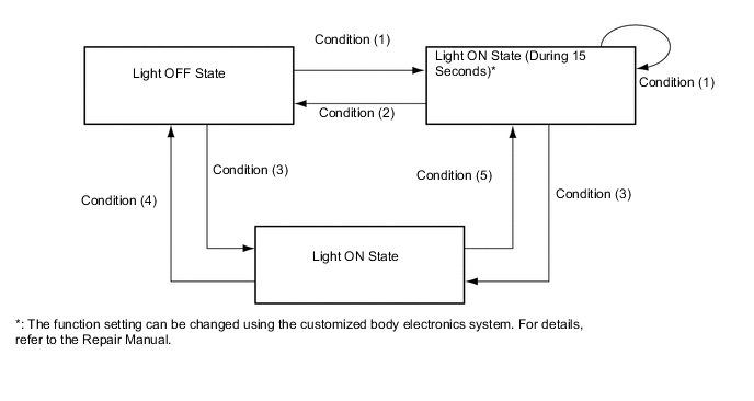
Condition Item Condition (1)
-
With engine switch OFF and all doors closed, key enters any actuation area around the doors.
-
With engine switch OFF, all doors closed and any door is unlocked.
Condition (2)
-
More than 15 seconds have elapsed in the light ON state (15 seconds duration)*.
-
All doors are closed and locked.
-
Engine switch is IG.
-
Key is outside of all actuation area around the doors.
-
A door other than the back door is open.
Condition (3) With engine switch OFF and all doors closed, any door is open. Condition (4) Engine switch is IG. Condition (5) All doors are closed. *: The function setting can be changed using the customized body electronics system. For details, refer to the Repair Manual.
-
-
-
Exterior Footwell Light Control
-
The exterior footwell light control consists primarily of the fade-in/fade-out function and timer illumination function.
-
The foot light control* operates as described in the diagram below when any one of the items for each condition is satisfied.
Tech Tips
*: The function setting can be changed using the customized body electronics system. For details, refer to the Repair Manual.
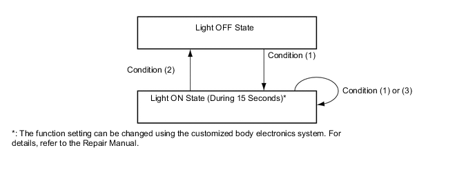
Condition Item Condition (1)
-
With engine switch OFF and all doors closed, key enters any actuation area around the doors.
-
With engine switch OFF, all doors closed and any door is unlocked.
Condition (2)
-
More than 15 seconds have elapsed in the light ON state (15 seconds duration)*.
-
All doors are closed and locked.
-
Engine switch is IG.
-
Key is outside of all actuation area around the doors.
Condition (3) A door other than the back door is open. *: The function setting can be changed using the customized body electronics system. For details, refer to the Repair Manual.
-
-
-
Battery Saving Control
-
Under the following condition, battery saving control turns off the lights illuminated by the illuminated entry control.
-
When any door is open, no door is opened or closed for approximately 20 minutes.
-
Engine switch is turned from ACC, IG to OFF.
-
-
-
Interior light auto cut function
-
When the front room light, No. 1 room light and No. 2 room light are illuminated by the each switch, and vanity lights are illuminated, these lights are turn off after 20 minutes after the engine switch is turned OFF.
-
-