LIGHTING
-
General
-
The daytime running light system is provided.
-
The daytime running light system is designed to automatically illuminate the Light Emitting Diode (LED) lights during the daytime to keep the vehicle highly visible to other vehicles.
-
The headlight light control ECU sub-assembly controls this system.
-
This system is enabled when the conditions given below are met:
-
The engine switch is ON (IG).
-
The engine speed signal is input (engine is running).
-
The light control switch is in the AUTO position (if headlight-on control is not being performed by the automatic light control system.)
-
The parking brake is OFF.
-
-
-
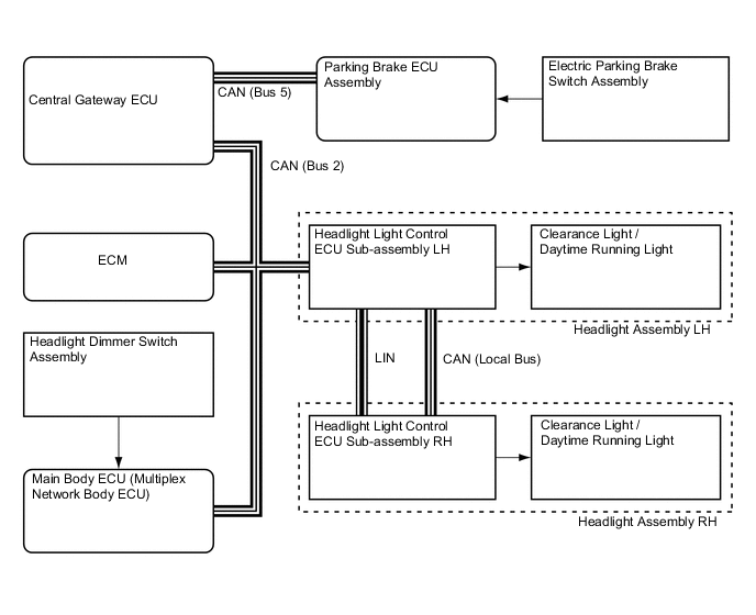
System Diagram
-
Layout of Main Components
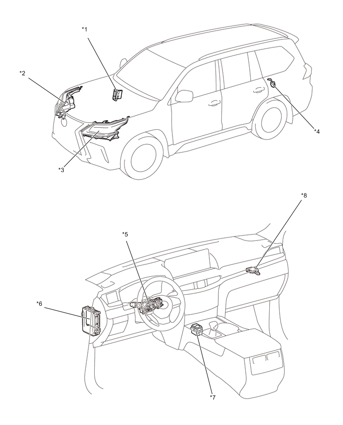
*1 ECM *2 Headlight Assembly RH
-
Headlight Light Control ECU Sub-assembly RH
*3 Headlight Assembly LH
-
Headlight Light Control ECU Sub-assembly LH
*4 Parking Brake ECU Assembly *5 Main Body ECU (Multiplex Network Body ECU) *6 Headlight Dimmer Switch Assembly *7 Electric Parking Brake Switch Assembly *8 Central Gateway ECU -
-
Function of Main Components
Component Function Main Body ECU (Multiplex Network Body ECU) Outputs a daytime running light request signal to the headlight light control ECU sub-assembly based on the signals from the each ECU and the switch. Headlight Light Control ECU Sub-assembly LH / RH Received the e daytime running light operation signal from the main body ECU and Illuminates the daytime running lights. ECM Transmits the engine speed signal to the main body ECU. Headlight Dimmer Switch Assembly Outputs a light control switch signal to the main body ECU. Parking Brake ECU Assembly Outputs a parking brake operation signal to the main body ECU. Electric Parking Brake Switch Assembly Outputs a parking brake application signal to the parking brake ECU assembly.