LIGHTING
-
General
-
The lane change flasher system flashes the turn signal light a certain number of times when the turn signal switch (headlight dimmer switch assembly) is moved to the lane change position. By using the lane change flasher system when changing lanes, it is no longer necessary to hold the turn signal switch in the lane change position.
-
-
System Diagram
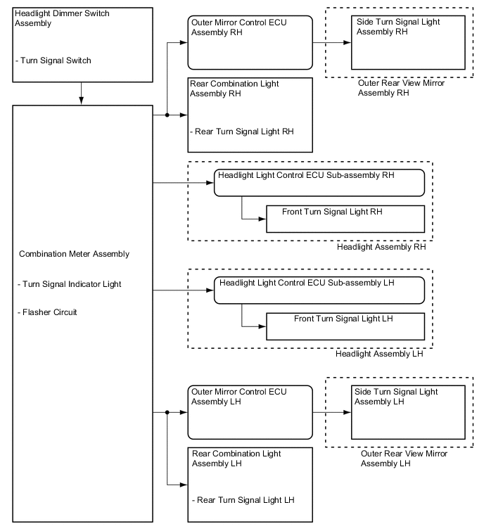
-
Layout of Main Components
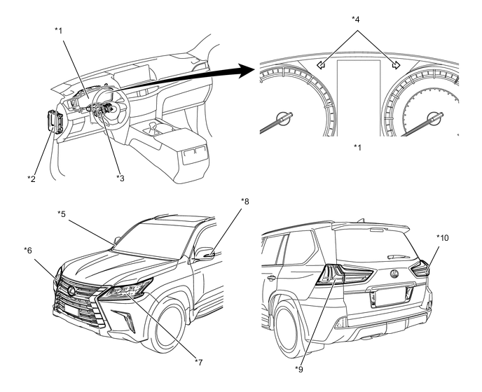
*1 Combination Meter Assembly *2 Main Body ECU (Multiplex Network Body ECU) *3 Headlight Dimmer Switch Assembly
-
Turn Signal Switch
*4 Turn Signal Indicator Light *5 Outer Rear View Mirror Assembly RH
-
Side Turn Signal Light Assembly RH
*6 Headlight Assembly RH
-
Headlight Light Control ECU Sub-assembly RH
-
Front Turn Signal Light RH
*7 Headlight Assembly LH
-
Headlight Light Control ECU Sub-assembly LH
-
Front Turn Signal Light LH
*8 Outer Rear View Mirror Assembly LH
-
Side Turn Signal Light Assembly LH
*9 Rear Combination Light Assembly LH
-
Rear Turn Signal Light LH
*10 Rear Combination Light Assembly RH
-
Rear Turn Signal Light RH
-
-
Construction
-
Turn Signal Switch (Headlight Dimmer Switch Assembly)
-
The lane change flasher system is operated by moving the turn signal switch to the lane change position.
-
After the turn signal switch has been moved to the lane change position, it will return to the neutral position once released from the hand.
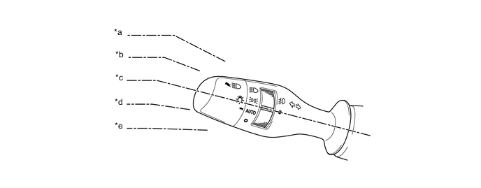
*a Right Cornering Position *b Right Lane Change Position *c Neutral Position *d Left Lane Change Position *e Left Cornering Position - -
-
-
-
Operation
-
The lane change flasher system operates in the following way:
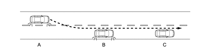
Condition Turn Signal Switch Turn Signal Light A Commencing lane changing Move to lane change position Starts flashing B During lane changing Not moved
-
If operation finishes during lane changing, flashing will start if the lane change position is moved to again.
Extinguishes after flashing 3 times* C Finishing lane changing Not moved
-
If the turn signal light is flashing even after lane changing has finished, moving the switch in the direction opposite to the current position will extinguish the light.
Extinguishes *: The flashing frequency can be configured by means of the customization function (customizable parameter: off, 3, 5, 7, 9 or 11). For details, refer to the Repair Manual.
-
-