1VD-FTV ENGINE
-
General
-
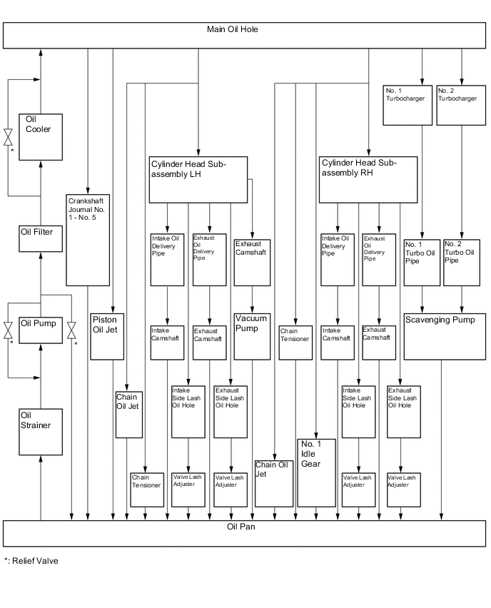
The lubrication circuit is fully pressurized and all oil passes through an oil cooler assembly and oil filter.
-
A trochoid gear type oil pump, which uses 2 oil pump gears, is provided.
-
A scavenging pump assembly is used to suppress the accumulation of oil in the turbocharger while driving on a slope.
-
A water-cooled type oil cooler is installed on oil filter bracket.
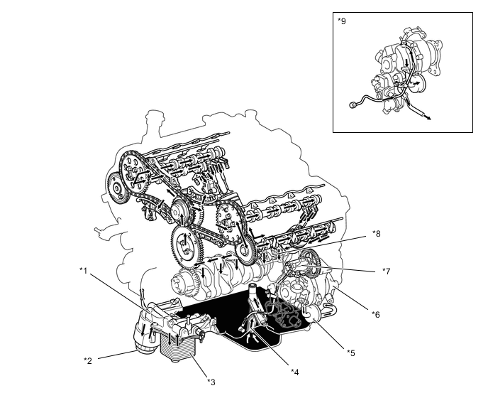
*1 Oil Filter Bracket Sub-assembly *2 Oil Filter *3 Oil Cooler Assembly *4 Oil Strainer Sub-assembly *5 Turbo Oil Pipe *6 No. 2 Turbocharger Sub-assembly *7 Scavenging Pump Assembly *8 Oil Pump Assembly *9 No. 1 Turbocharger Sub-assembly - - Figure 1. Oil Circuit
-
-
Oil Pump
-
A trochoid gear type oil pump assembly is used. The oil pump assembly uses 2 oil pump gears and is driven by a gear engaged with the crankshaft.
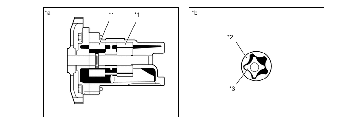
*1 Oil Pump Gear *2 Driven Gear *3 Drive Gear - - *a Oil Pump Cross Section *b Oil Pump Gear Cross Section
-
-
Oil Jet
-
No. 1 oil nozzle sub-assemblies are provided at the bottom of the cylinder block assembly to spray oil to the piston's cooling channel, thus further cooling and lubricating the pistons.
-
These oil jets contain a check valve to prevent oil from being fed when the oil pressure is low. This prevents the overall oil pressure in the engine from dropping.
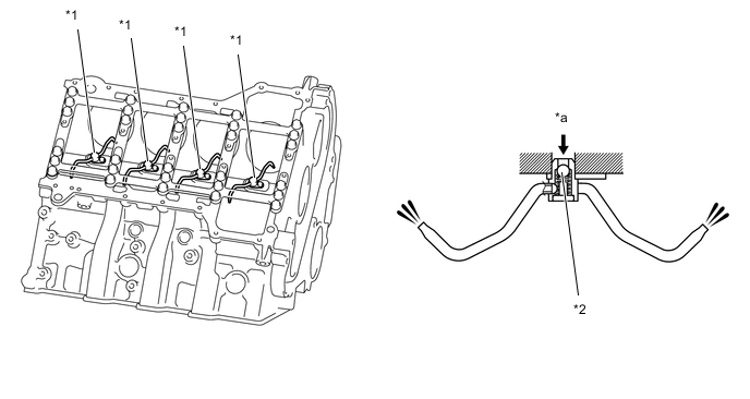
*1 No. 1 Oil Nozzle Sub-assembly *2 Check Valve *a Engine Oil - -
-
-
Oil Filter
-
An oil filter with a replaceable element is used. The oil filter element uses a high-performance filter paper to improve filtration performance. It is also combustible for environmental protection.
-
A plastic oil filter cap is used.
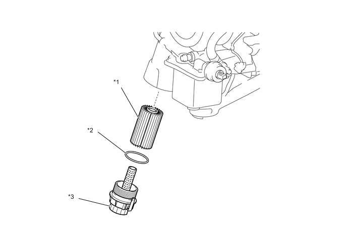
*1 Oil Filter Element *2 O-ring *a Oil Filter Cap - -
-
-
Scavenging Pump
-
The scavenging pump assembly, which is located at the back end of the cylinder block sub-assembly, is driven by the crankshaft via gears.
-
After the turbocharger discharges the oil, the scavenging pump assembly returns the oil from the turbo oil pipe through a forced suction and discharges it to the oil pan.
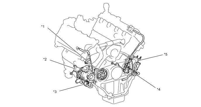
*1 Scavenging Pump Assembly *2 No. 2 Turbocharger Sub-assembly *3 No. 2 Turbo Oil Pipe *4 No. 1 Turbo Oil Pipe *5 No. 1 Turbocharger Sub-assembly - - Figure 2. Scavenging Pump Cross Section
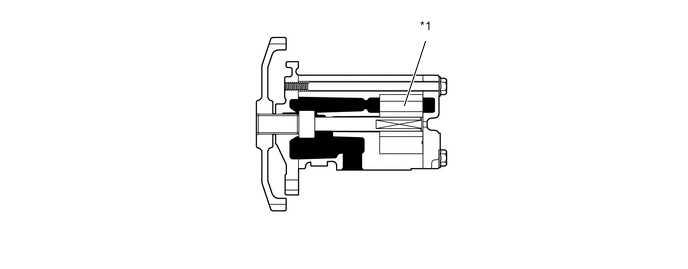
*1 Oil Pump Gear - - Figure 3. Scavenging Pump Gear Cross Section

*1 Driven Gear *2 Drive Gear Pump Components and Functions Component Function Turbo Oil Pipe The turbo oil pipe separates the oil discharged by the turbocharger into gas and liquid. Scavenging Pump Assembly Returns the oil from the turbo oil pipe by suction, and discharges it to the oil pan. Figure 4. System Diagram
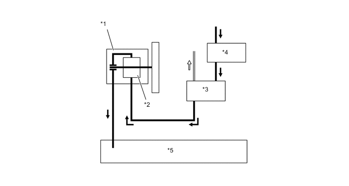
*1 Scavenging Pump Assembly *2 Oil Pump Gear *3 Turbo Oil Pipe *4 Turbocharger Sub-assembly *5 Oil Pan - - 
Gas 
Oil
-