1VD-FTV ENGINE
-
General
-
Each cylinder has 2 intake valves and 2 exhaust valves. Intake and exhaust efficiency is increased by means of the larger total port areas.
-
The timing gear train uses a combination of gears and chain sub-assemblies.
-
This engine uses roller rocker arms with built-in needle bearings. This reduces the friction that occurs between the cams and the areas (roller rocker arms) that push the valves down, thus improving fuel economy.
-
Valve lash adjuster assemblies, which maintain a constant zero valve clearance through the use of oil pressure and spring force, are used.
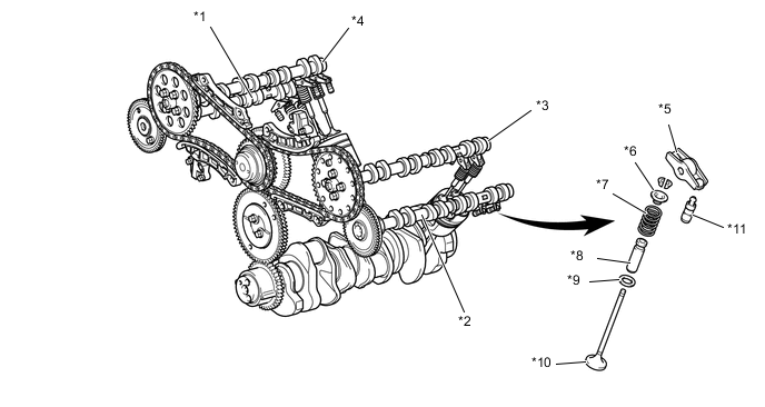
*1 Exhaust Camshaft (No. 2 Camshaft) *2 Exhaust Camshaft (No. 4 Camshaft Sub-assembly) *3 Intake Camshaft (No. 3 Camshaft Sub-assembly) *4 Intake Camshaft (Camshaft) *5 Valve Rocker Arm Sub-assembly *6 Valve Spring Retainer *7 Inner Compression Spring *8 Valve Guide Bush *9 Valve Spring Seat *10 Valve *11 Valve Lash Adjuster Assembly - -
-
-
Timing Gear Train
-
An intake camshaft is driven by gears and a timing chain, and the exhaust camshaft is driven by a cam gear attached to the intake camshaft.
-
Chain sub-assemblies use bush chains with a pitch of 9.525mm (0.375 in.).
-
The chain sub-assemblies are lubricated by an oil jet.
-
Chain tensioners use a spring and oil pressure to maintain proper chain tension at all times. They suppress noise generated by the chain sub-assemblies.
-
The chain tensioners are the ratchet type with a non-return mechanism.
-
The No. 1 Idle gear and cam gear are constructed with a scissors gear to reduce noise.
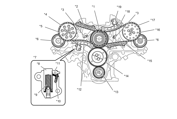
*1 Fuel Supply Pump Drive Gear *2 No. 1 Chain Vibration Damper *3 Oil Jet *4 No. 1 Timing Chain (Chain Sub-assembly) *5 No. 1 Camshaft Timing Sprocket *6 Cam Gear *7 No. 1 Chain Tensioner Assembly *8 Plunger *9 Spring *10 Cam Spring *11 Cam *12 No. 1 Chain Tensioner Slipper *13 Crankshaft Timing Gear *14 No. 1 Idle Gear *15 No. 2 Chain Vibration Damper *16 No. 2 Camshaft Timing Sprocket *17 No. 2 Timing Chain (Chain Sub-assembly) *18 No. 2 Chain Tensioner Slipper *19 No. 2 Chain Tensioner Assembly - -
-
-
Timing Chain Cover
-
The timing chain or belt cover sub-assembly has an integrated construction consisting of the cooling system (engine water pump aseembly and water passage). Thus, the number of parts has been reduced for weight reduction.
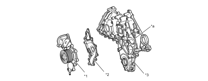
*1 Engine Water Pump Assembly *2 Water Pump Gasket *3 Timing Chain or Belt Cover Sub-assembly - - *a Water Pump Swir lChamber - -
-
-
Hydraulic Lash Adjuster
-
The valve lash adjuster assembly, which is located at the fulcrum of the roller rocker arm sub-assembly, consists primarily of a plunger, plunger spring, check ball, and check ball spring.
-
The engine oil that is supplied by the cylinder head sub-assembly and the built-in spring actuates the valve lash adjuster assembly. The oil pressure and the spring force that act on the plunger push the roller rocker arm sub-assembly against the cam, in order to adjust the valve clearance that is created during the opening and closing of the valve. As a result, engine noise is reduced.
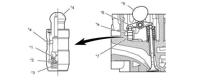
*1 Check Ball *2 Check Ball Spring *3 Plunger Spring *4 Plunger *5 Cam *6 Roller Rocker Arm Sub-assembly *7 Valve Lash Adjuster Assembly - - *a Oil Passage - - Tech Tips
Valve clearance adjustment is not necessary because a valve lash adjusters are used in this model.
-