3UR-FE ENGINE
-
General
-
The engine control system of the 3UR-FE engine has the following features.
System Outline Sequential Multiport Fuel Injection (SFI)
-
An L-type EFI system directly detects the intake air mass using a hot wire type intake mass air flow meter sub-assembly.
-
An independent injection system (in which fuel is injected once into each intake port for each two revolutions of the crankshaft) is used.
-
Fuel injection takes two forms:
-
Synchronous injection, in which injection always occurs at the same timing relative to the firing order.
-
Non-synchronous injection in which injection is effected regardless of the crankshaft angle.
-
Synchronous injection is further divided into group injection during a cold start, and independent injection after the engine is started.
Electronic Spark Advance (ESA)
-
Ignition timing is determined by the ECM based on signals from various sensors. The ECM corrects ignition timing in response to engine knocking.
-
This system selects the optimal ignition timing in accordance with the signals received from the sensors and sends the (IGT) ignition signal to the igniter.
Electronic Throttle Control System-intelligent (ETCS-i) Optimally controls the throttle valve opening in accordance with the amount of accelerator pedal effort and the condition of the engine and the vehicle. Dual Variable Valve Timing-intelligent (VVT-i) Controls the intake and exhaust camshafts to optimal valve timing in accordance with the engine operating conditions. Acoustic Control Induction System (ACIS) The intake air passages are switched based on engine speed and throttle valve opening angle to provide high performance in all engine speed ranges. Fuel Pump Control
-
Based on signals from the ECM, the fuel pump ECU controls the fuel pump speed.
-
The fuel pump is stopped when the SRS airbag is deployed in a frontal, side, or side rear collision.
Air Injection Control* The ECM controls the air injection time based on the signals from the crankshaft position sensor, water temperature sensor, air flow meter and air pressure sensor. Starter Control (Cranking Hold Function) Once the engine switch is pushed, while the brake pedal is depressed, this control continues to operate the starter until the engine started. Air Fuel Ratio Sensor and Oxygen Sensor Heater Control Maintains the temperature of the air fuel ratio sensors or oxygen sensors at an appropriate level to increase the detection accuracy of the exhaust gas oxygen concentration. Air Conditioning Cut-off Control By turning the air conditioning compressor on or off in accordance with the engine condition, drivability is maintained. Evaporative Emission Control The ECM controls the purge flow of evaporative emission (HC) in the charcoal canister in accordance with the engine conditions. Engine Immobiliser Prohibits fuel delivery and ignition if an attempt is made to start the engine with an invalid key. Brake Override System The driving torque is restricted when both the accelerator and brake pedals are depressed. (For the Activation Conditions and Inspection Method, refer to the repair manual.) Diagnosis When the ECM detects a malfunction, it records the malfunction and memorizes information related to the fault. Fail-safe When the ECM detects a malfunction, it stops or controls the engine according to the data already stored in the memory. *: Models with air injection control
-
-
-
Construction
-
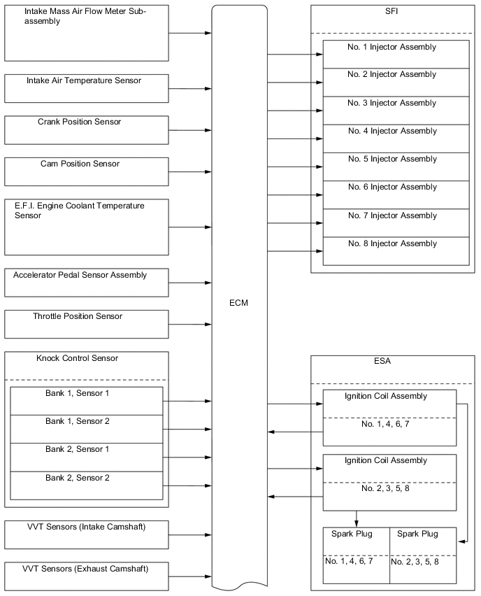
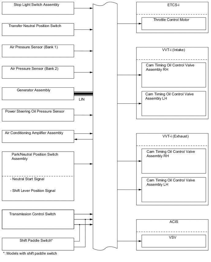
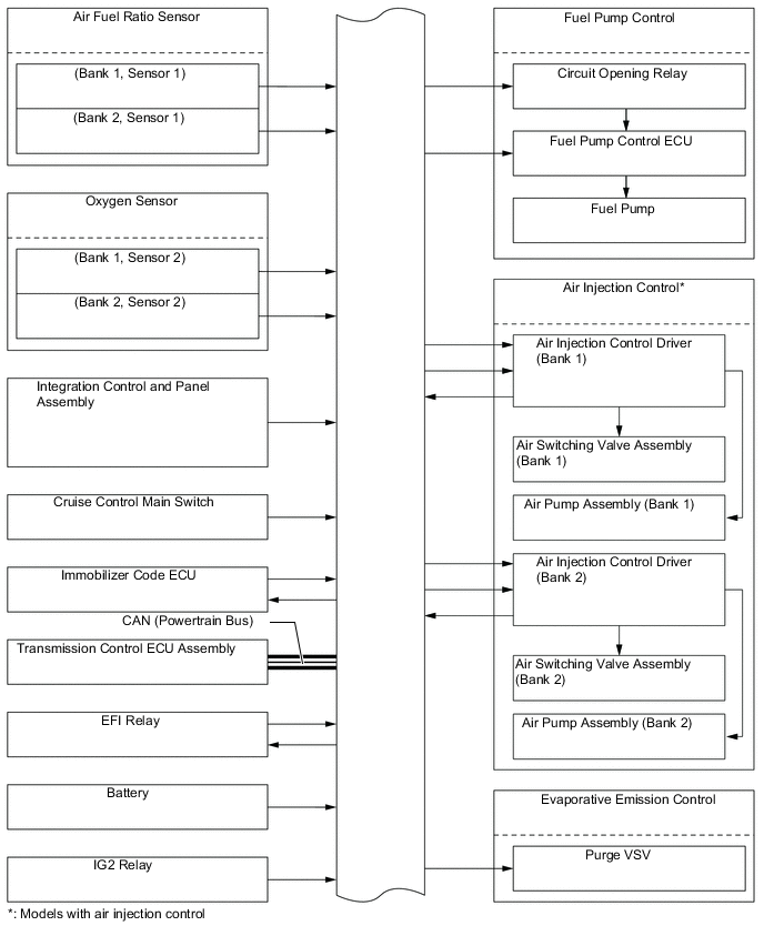
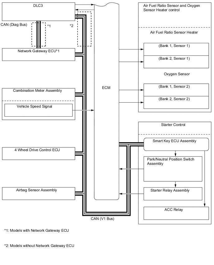
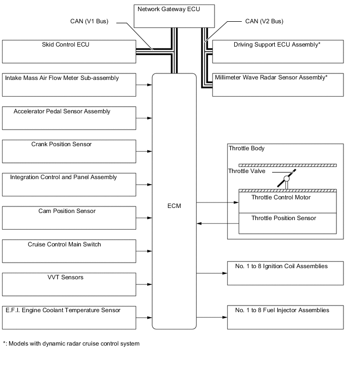
The configuration of the engine control system is as shown in the following chart.
-
-
Layout of Main Components
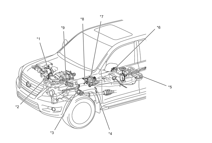
*1 Intake Mass Air Flow Meter Sub-assembly
-
Intake Air Temperature Sensor
*2 Throttle Body
-
Throttle Position Sensor
-
Throttle Control Motor
*3 Air Fuel Ratio Sensor (Bank 1, Sensor 1) *4 Oxygen Sensor (Bank 1, Sensor 2) *5 Fuel Suction Tube with Pump and Gauge Assembly *6 Fuel Pump ECU *7 Charcoal Canister *8 Oxygen Sensor (Bank 2, Sensor 2) *9 Air Fuel Ratio Sensor (Bank 2, Sensor 1) - - 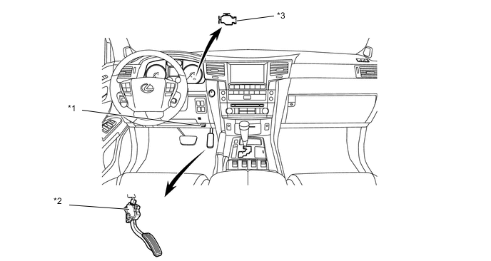
*1 DLC3 *2 Accelerator Pedal Sensor Assembly *3 Malfunction Indicator Lamp (MIL) - - 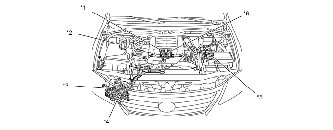
*1 Air Switching Valve (Bank 2)
-
Air Pressure Sensor
*2 ECM *3 Air Pump (Bank 2) *4 Air Pump (Bank 1) *5 Air Injection Control Driver *6 Air Switching Valve (Bank 1)
-
Air Pressure Sensor
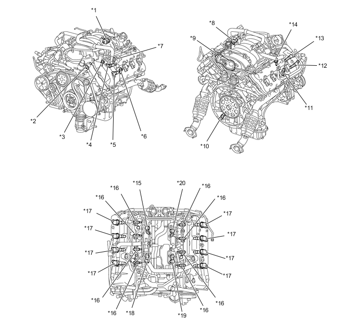
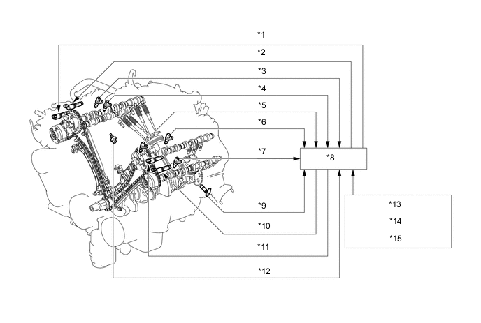
*1 Purge VSV *2 Engine Coolant Temperature Sensor *3 Cam Position Sensor *4 Camshaft Timing Oil Control Valve (Bank 1, Intake) *5 Camshaft Timing Oil Control Valve (Bank 1, Exhaust) *6 VVT Sensor (Bank 1, Exhaust) *7 VVT Sensor (Bank 1, Intake) *8 VSV (For ACIS) *9 ACIS Actuator *10 Crank Position Sensor *11 VVT Sensor (Bank 2, Exhaust) *12 Camshaft Timing Oil Control Valve (Bank 2, Exhaust) *13 Camshaft Timing Oil Control Valve (Bank 2, Intake) *14 VVT Sensor (Bank 2, Intake) *15 Knock Control Sensor 2 (Bank 2) *16 Fuel Injector *17 Ignition Coil (with Igniter) *18 Knock Control Sensor 1 (Bank 2) *19 Knock Control Sensor 1 (Bank 1) *20 Knock Control Sensor 2 (Bank 1) -
-
Main Components of Engine Control System
-
General
-
The main components of the 3UR-FE engine control system are as follows:
Component Outline Quantity Function ECM 32-bit CPU
(DENSO)
1 The ECM optimally controls the engine control system to suit the operating conditions of the engine in accordance with the signals provided by the sensors. Intake Mass Air Flow Meter Sub-assembly Hot-wire Type 1 This sensor has a built-in hot-wire to directly detect the intake air mass and flow rate. Intake Air Temperature Sensor Thermistor Type 1 This sensor detects the intake air temperature by means of an internal thermistor. Crank Position Sensor MRE Type (Rotor Teeth/36-2) 1 This sensor detects the engine speed and the crankshaft position. Cam Position Sensor MRE Type (Rotor Teeth/3) 1 This sensor detects the camshaft position and performs the cylinder identification. VVT Sensor (Intake) MRE Type (Rotor Teeth/3) 1 each bank This sensor detects the actual valve timing. VVT Sensor (Exhaust) MRE Type (Rotor Teeth/3) 1 each bank This sensor detects the actual valve timing. Accelerator Pedal Sensor Assembly Hall IC Type (Non-contact Type) 1 This sensor detects the amount of pedal effort applied to the accelerator pedal. Throttle Position Sensor Hall IC Type (Non-contact Type) 1 This sensor detects the throttle valve opening angle. Knock Control Sensor Built-in Piezoelectric Element (Flat Type) 2 each bank This sensor detects an occurrence of the engine knocking indirectly from the vibration of the cylinder block caused by the occurrence of engine knocking. Oxygen Sensor Cup Type with Heater 1 each bank This sensor detects the oxygen concentration in the exhaust emission by measuring the electromotive force which is generated in the sensor itself. Air Fuel Ratio Sensor Planar Type with Heater 1 each bank As with the oxygen sensor, this sensor detects the oxygen concentration in the exhaust emission. However, it detects the oxygen concentration in the exhaust emission linearly. Engine Coolant Temperature Sensor Thermistor Type 1 This sensor detects the engine coolant temperature by means of an internal thermistor. Fuel Injector 12-hole Type 8 This fuel injector contains an electro-magnetically operated nozzle to inject fuel into the intake port. Camshaft Timing Oil Control Valve Electro-magnetic Coil Type 2 each bank The camshaft timing oil control valve changes the valve timing by switching the oil passage that acts on the VVT-i controller in accordance with the signals received from the ECM.
-
-
Intake Mass Air Flow Meter Sub-assembly
-
This intake mass air flow meter sub-assembly, which is a slot-in type, allows a portion of the intake air to flow through the detection area. By directly measuring the mass and the flow rate of the intake air, the detection precision is improved and the intake air resistance is reduced.
-
This intake mass air flow meter sub-assembly has a built-in intake air temperature sensor.
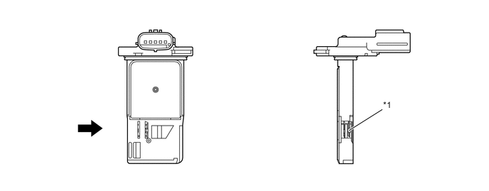
*1 Intake Air Temperature Sensor - - 
Air Flow - -
-
-
Crank Position Sensor, Cam Position Sensor and VVT Sensor
-
General
-
Magnetic Resistance Element (MRE) sensors are used for the crank position, cam position, and VVT sensors.
-
The timing rotor for the crank position sensor is installed on the back end of the crankshaft. The timing rotor has 34 teeth, with 2 teeth missing, at 10° intervals. Based on these teeth, the crank position sensor transmits crankshaft position signals (NE signal) consisting of 33 high/low output pulses every 10° per revolution of the crankshaft, and 1 high/low output pulse every 30°. The ECM uses the NE signal for detecting the crankshaft position as well as for detecting the engine speed. It uses the missing teeth signal for determining the top-dead-center.
-
The cam position sensor uses a timing rotor that is installed on the front end of the intake camshaft sprocket of the left bank. Based on the timing rotor, the sensor outputs camshaft position signals (G2 signal) consisting of 3 (3 high output, 3 low output) pulses for every 2 revolutions of the crankshaft. The ECM compares the G2 and NE signals to detect the camshaft position and identify the cylinder.
-
The VVT sensors (intake and exhaust) use timing rotors that are installed on the intake and exhaust camshafts of each bank. Based on the timing rotors, the sensors output VVT position signals consisting of 3 (3 high output, 3 low output) pulses for every 2 revolutions of the crankshaft. The ECM compares these VVT position signals to the NE signal to detect the actual valve timing.
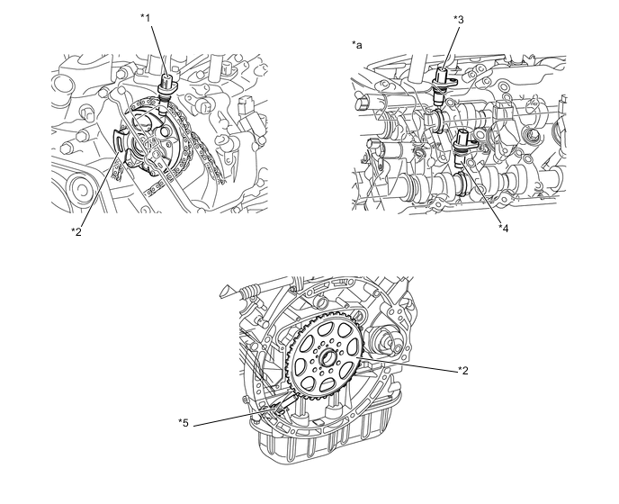
*1 Cam Position Sensor *2 Timing Rotor *3 VVT Sensor (Intake) *4 VVT Sensor (Exhaust) *5 Crank Position Sensor - - *a Bank 1 - - Figure 1. Wiring Diagram (Crank Position Sensor Circuit)
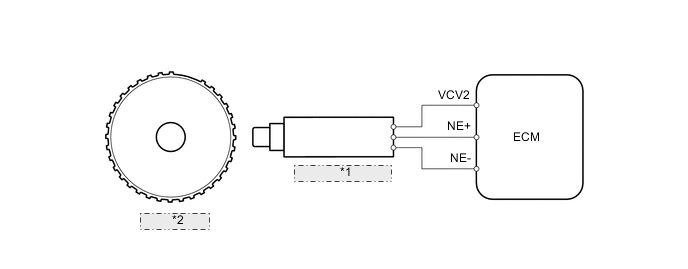
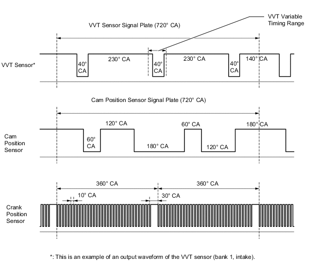
*1 Crank Position Sensor *2 Timing Rotor Figure 2. Sensor Output Waveforms
-
-
MRE Type Sensor
-
The MRE type sensor consists of an MRE, a magnet and a sensor.
-
The direction of the magnetic field changes due to the profile (protruding and non-protruding portions) of the timing rotor, which passes by the sensor. As a result, the resistance of the MRE changes, and the output voltage to the ECM changes to high or low. The ECM detects the crankshaft and camshaft position based on this output voltage.
-
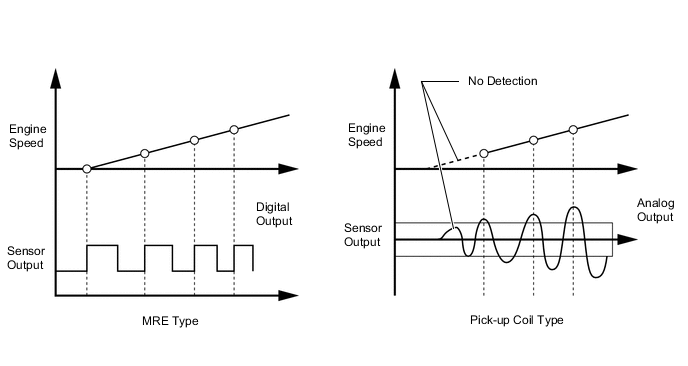
The differences between the MRE type sensor and the pick-up coil type sensor used on a conventional model are as follows.
-
An MRE type sensor outputs a constant level of high/low digital signals regardless of the engine speed. Therefore, an MRE type sensor can detect the positions of the crankshaft and camshaft at an early stage of cranking.
-
A pickup coil type sensor outputs analog signals with levels that change with the engine speed.
Figure 3. MRE Type and Pick-up Coil Type Output Waveform Image Comparison
-
-
-
Accelerator Pedal Sensor Assembly
-
The no-contact type accelerator pedal sensor assembly uses a Hall IC, which is mounted on the accelerator pedal arm.
-
A magnetic yoke is mounted at the base of the accelerator pedal arm. This yoke rotates around the Hall IC in accordance with the amount of effort that is applied to the accelerator pedal. The Hall IC converts the changes that occur in the magnetic flux into electrical signals, and outputs them in the form of accelerator pedal position signals to the ECM.
-
The Hall IC contains two circuits, one for the main signal, and the other for the sub signal. It converts the accelerator pedal position (angle) into electric signals that have differing characteristics and outputs them to the ECM.
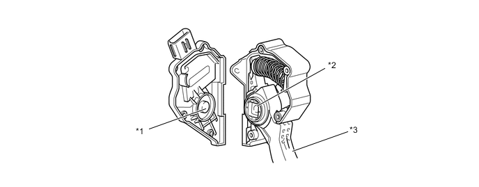
*1 Hall IC *2 Magnetic Yoke *3 Accelerator Pedal Arm - - 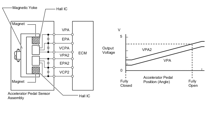
-
-
Throttle Position Sensor
-
The no-contact type throttle position sensor uses a Hall IC, which is mounted on the throttle body.
-
The Hall IC is surrounded by a magnetic yoke. The Hall IC converts the changes that occur in the magnetic flux into electrical signals, and outputs them in the form of throttle valve position signals to the ECM.
-
The Hall IC contains circuits for the main and sub signals. It converts the throttle valve opening angle into two electrical signals that have differing characteristics and outputs them to the ECM.
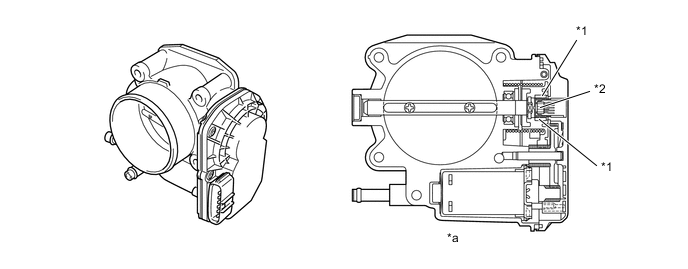
*1 Magnet *2 Hall IC *a Cross Section - - 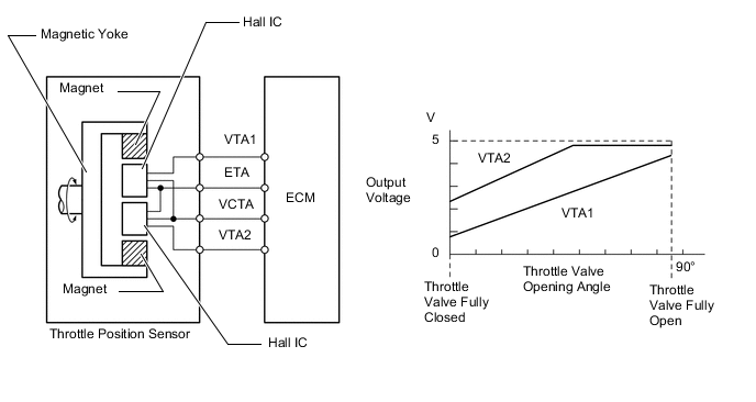
-
-
Knock Control Sensor (Flat Type)
-
General
-
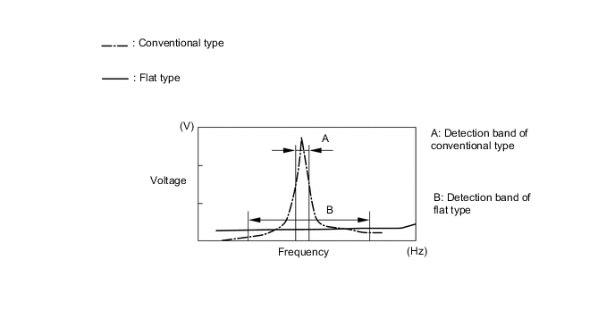
In the conventional type knock control sensor (resonant type), a vibration plate, which has the same resonance point as the knocking frequency of the engine, is built in and can detect the vibration in this frequency band.
-
On the other hand, a flat type knock control sensor (non-resonant type) has the ability to detect vibration in a wider frequency band from approximately 6 kHz to 15 kHz, and has the following features:
-
The engine knocking frequency will change slightly depending on the engine speed. The flat type knock control sensor can detect vibration even when the engine knocking frequency is changed. Thus the vibration detection ability is increased compared to the conventional type knock control sensor, and a more precise ignition timing control is possible.
Figure 4. Characteristic of Knock Control Sensor
-
-
Construction
-
The flat type knock control sensor is installed on the engine through the stud bolt installed on the cylinder block. For this reason, a hole for the stud bolt runs through the center of the sensor.
-
Inside of the sensor, a steel weight is located on the upper portion and a piezoelectric element is located under the weight through the insulator.
-
The open/short circuit detection resistor is integrated.
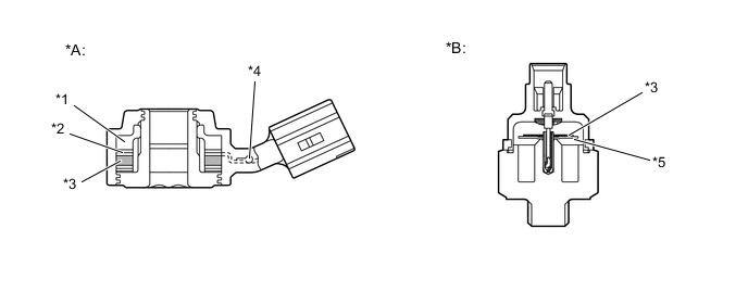
*A Flat Type Knock Control Sensor (Non-resonant Type) *B Conventional Type Knock Control Sensor (Resonant Type) *1 Steel Weight *2 Insulator *3 Piezoelectric Element *4 Open/Short Circuit Detection Resistor *5 Vibration Plate - -
-
-
Operation
-
The knocking vibration is transmitted to the steel weight and its inertia applies pressure to the piezoelectric element. This action generates electromotive force (voltage).
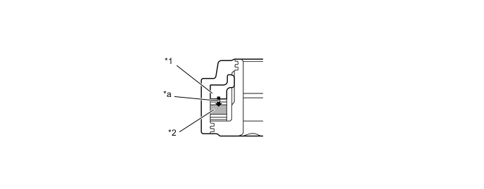
*1 Steel Weight *2 Piezoelectric Element *a Inertia - -
-
-
Open/Short Circuit Detection Resistor
-
While the engine switch is on (IG), the open/short circuit detection resistor in the knock control sensor and the resistor in the ECM keep the voltage at the terminal KNK1 of engine constant.
-
An Integrated Circuit (IC) in the ECM constantly monitors the voltage of the terminal KNK1. If the open/short circuit occurs between the knock control sensor and the ECM, the voltage of the terminal KNK1 changes and the ECM detects the open/short circuit and stores a DTC (Diagnostic Trouble Code).
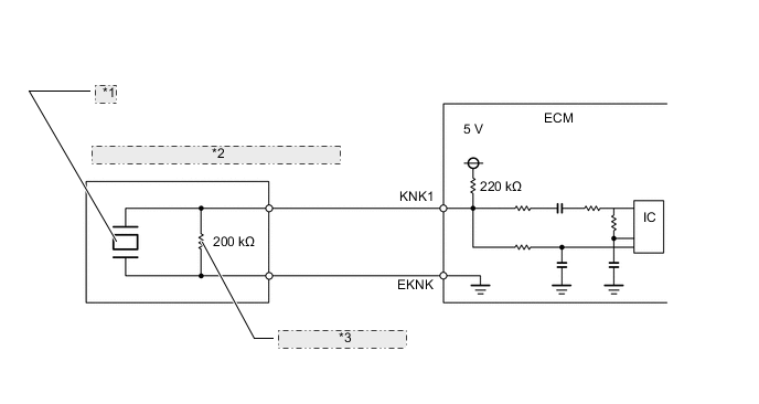
*1 Piezoelectric Element *2 Knock Control Sensor (Bank 1, Sensor 1) *3 Open/Short Circuit Detection Resistor
Tech Tips
These knock control sensors are mounted in specific directions at specific angles. To prevent the right and left bank wiring connectors from being interchanged, make sure to install each sensor in its prescribed direction. For details, refer to the Repair Manual.
-
-
-
Air Fuel Ratio Sensor and Oxygen Sensor
-
General
-
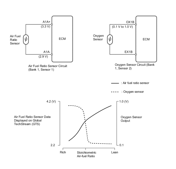
The oxygen sensor and the air fuel ratio sensor differ in output characteristics.
-
The output voltage of the oxygen sensor changes in accordance with the oxygen concentration in the exhaust gas. The ECM uses this output voltage to determine whether the present air-fuel ratio is richer or leaner than the stoichiometric air-fuel ratio.
-
Approximately 0.4 V is constantly applied to the air fuel ratio sensor, which outputs an amperage that varies in accordance with the oxygen concentration in the exhaust gas. The ECM converts the changes in the output amperage into voltage in order to linearly detect the present air-fuel ratio.
-
-
Construction
-
The basic construction of the oxygen sensor and the air fuel ratio sensor is the same. However, they are divided into the cup type and the planar type, in accordance with the different types of heater construction that are used.
-
The cup type sensor contains a sensor element that surrounds a heater.
-
The planar type sensor uses alumina, which excels in heat conductivity and insulation, to integrate a sensor element with a heater, thus improving the warm-up performance of the sensor.
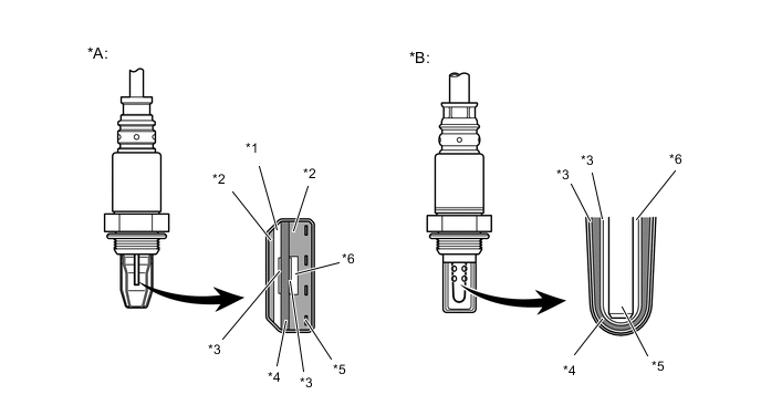
*A Air Fuel Ratio Sensor (Planar Type) *B Oxygen Sensor (Cup Type) *1 Dilation Layer *2 Alumina *3 Platinum Electrode *4 Sensor Element (Zirconia) *5 Heater *6 Atmosphere The illustrations above are intended to show the differences in the basic construction between the cup type sensor and the planner type sensor, so the illustrated sensor shapes may differ from the actual ones.
-
-
-
-
Electronic Throttle Control System-intelligent (ETCS-i)
-
General
-
In the conventional throttle body, the throttle valve angle is determined invariably by the amount of the accelerator pedal effort. In contrast, ETCS-i uses the ECM to calculate the optimal throttle valve angle that is appropriate for the respective driving condition and uses a throttle control motor to control the angle.
-
In case of an abnormal condition, this system transfers to the fail-safe mode.
Figure 5. System Diagram
-
-
Control
-
General
-
The ETCS-i consists of the following functions:
-
Normal Throttle Control (non-linear control)
-
Idle Speed Control (ISC)
-
Active Traction Control (A-TRC)
-
Vehicle Stability Control (VSC) Coordination Control
-
Crawl Control (CRAWL) Coordination Control
-
Cruise Control
-
Dynamic Radar Cruise Control*
-
*: Models with dynamic radar cruise control system
-
-
Normal Throttle Control (Non-linear Control)
-
General
-
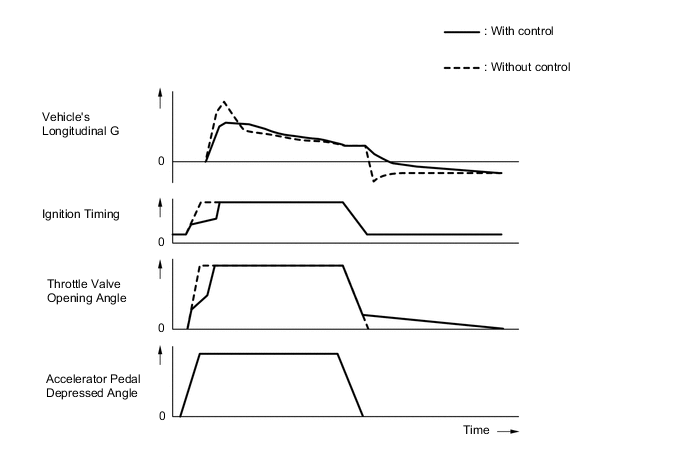
Controls the throttle to an optimal throttle valve angle that is appropriate for the driving conditions such as the amount of the accelerator pedal effort and the engine speed in order to achieve excellent throttle control and comfort in all operating ranges.
Figure 6. Conceptual Diagrams of Engine Control During Acceleration and Deceleration
-
2nd Start Control
-
In situations in which low-μ (low friction) road surface conditions can be anticipated, such as when the vehicle is driving in the snow, the rate of throttle valve opening can be controlled to ensure vehicle stability while the vehicle is driving on a slippery surface. This is accomplished by turning on 2nd start control. Pressing the 2nd side of the pattern select switch activates this control. This control modifies the relationship and reaction of the throttle to the accelerator pedal, and assists the driver by reducing the engine output from that of a normal level.
-
-
Idle Speed Control
-
The ECM controls the throttle valve in order to constantly maintain an ideal idle speed.
-
-
A-TRC
-
As part of the A-TRC, the throttle valve opening is reduced by a demand signal sent from the skid control ECU to the ECM. This demand signal will be sent if an excessive amount of slippage occurs at a drive wheel, thus ensuring vehicle stability and applying the appropriate amount of power to the road.
-
-
VSC Coordination Control
-
In order to bring the effectiveness of the VSC into full play, the throttle valve angle is regulated through a coordination control with the skid control ECU.
-
-
CRAWL Coordination Control
-
While the CRAWL is operating, the throttle valve is regulated through a coordination control with the skid control ECU.
-
-
Cruise Control
-
The ECM directly actuates the throttle valve for operation of the cruise control.
-
-
Dynamic Radar Cruise Control*
-
The dynamic radar cruise control uses a millimeter wave radar sensor and the distance control ECU to determine the distance, direction, and relative speed to a vehicle ahead. Thus, the system can effect deceleration control, follow-up control, constant speed control, and acceleration control. To make these controls possible, the ECM controls the throttle valve.
-
*: Models with dynamic radar cruise control system
-
-
-
-
Dual Variable Valve Timing-intelligent (VVT-i) System
-
General
-
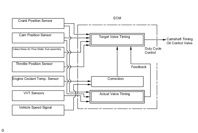
The Dual VVT-i system is designed to control the intake and exhaust camshafts within a range of 60° and 30° respectively (of Crankshaft Angle) to provide valve timing that is optimally suited to the engine operating conditions. This improves torque in all the speed ranges as well as increasing fuel economy, and reducing exhaust emissions.
*1 Camshaft Timing Oil Control Valve (Bank 2, Exhaust) *2 Camshaft Timing Oil Control Valve (Bank 2, Intake) *3 VVT Sensor (Bank 2, Exhaust) *4 VVT Sensor (Bank 2, Intake) *5 Cam Position Sensor *6 VVT Sensor (Bank 1, Intake) *7 VVT Sensor (Bank 1, Exhaust) *8 ECM *9 Crank Position Sensor *10 Camshaft Timing Oil Control Valve (Bank 1, Exhaust) *11 Camshaft Timing Oil Control Valve (Bank 1, Intake) *12 Engine Coolant Temperature Sensor *13 Intake Mass Air Flow Meter Sub-assembly *14 Throttle Position Sensor *15 Vehicle Speed Signal - - -
By using the engine speed, intake air mass, throttle position and engine coolant temperature, the ECM calculates optimal valve timing for each driving condition and controls the camshaft timing oil control valves. In addition, the ECM uses signals from the intake and exhaust VVT sensors for each bank and the crank position sensor to detect the actual valve timing, thus providing feedback control to achieve the target valve timing.
-
-
Effectiveness of Dual VVT-i System
Condition Operation Timing/Position Objective Effect During Idling 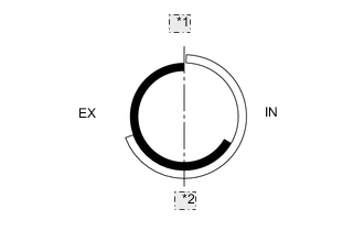
*1 TDC *2 BDC IN Most Retarded Position Eliminating overlap to reduce blow back to the intake side.
-
Stabilized idle speed
-
Better fuel economy
EX Most Advanced Position In Low Speed Range with Light to Medium Load 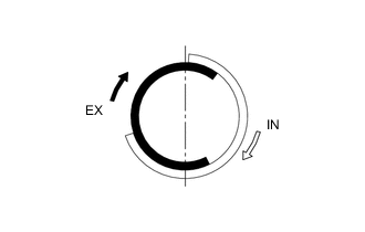
IN Retarded Retarding the intake valve close timing and reducing pumping loss. Increasing overlap and internal EGR.
-
Better fuel economy
-
Improved emission control
EX Retarded In Low to Medium Speed Range with Heavy Load 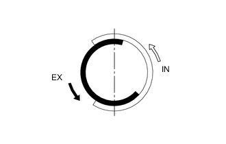
IN Advanced Advancing the intake valve close timing, reducing intake air blow back to the intake side, and improving volumetric efficiency. Improved torque in low to medium speed range EX Advanced In High Speed Range with Heavy Load 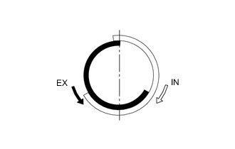
IN Retarded Retarding the intake valve close timing and improving volumetric efficiency using the inertia force of the intake air. Improved output EX Advanced At Low Temperatures 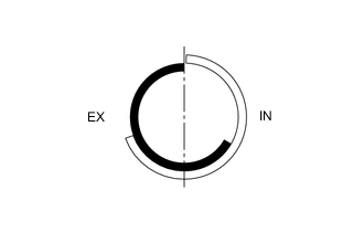
IN Most Retarded Position Eliminating overlap to reduce blow back to the intake side. Fixing valve timing at extremely low temperatures and increasing the control range as the temperature rises.
-
Stabilized fast idle speed
-
Better fuel economy
EX Most Advanced Position
-
Upon Starting
-
Stopping Engine
IN Most Retarded Position Controlling valve timing and fixing it to the optimal timing for engine start. Improved startability EX Most Advanced Position -
-
Construction
-
VVT-i Controller
-
This controller consists of an outer housing that is driven by the timing chain sprocket, and a vane sub-assembly that is coupled to each camshaft.
-
The intake side uses a VVT-i controller with 3 vanes, and the exhaust side uses one with 4 vanes.
-
When the engine stops, the intake side VVT-i controller is locked at the most retarded angle by its lock pin, and the exhaust side controller is locked at the most advanced angle. This ensures excellent engine startability.
-
The oil pressure sent from the advance or retard side passages of the intake and exhaust camshafts causes rotation of the VVT-i controller vane sub-assembly relative to the timing chain sprocket, to vary the valve timing continuously.
-
An advance assist spring is provided on the exhaust side VVT-i controller. This helps to apply torque in the advanced angle direction so that the vane lock pin securely engages with the housing when the engine stops.
Figure 7. Intake Side VVT-i Controller
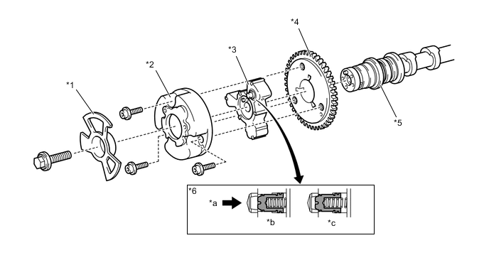
*1 Timing Rotor *2 Outer Housing *3 Vane Sub-assembly (Coupled to Intake Camshaft) *4 Timing Chain Sprocket *5 Intake Camshaft *6 Lock Pin *a Oil Pressure *b Engine Operating *c Engine Stopped - - Figure 8. Exhaust Side VVT-i Controller
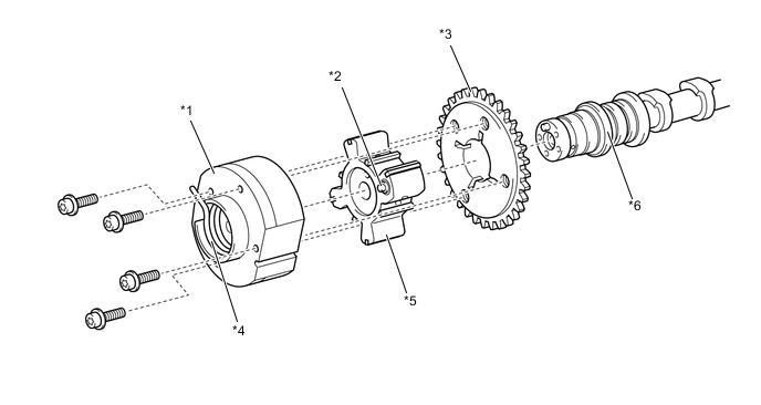
*1 Outer Housing *2 Lock Pin *3 Timing Chain Sprocket *4 Advanced Assist Spring *5 Vane Sub-assembly (Fixed on Exhaust Camshaft) *6 Exhaust Camshaft
-
-
Camshaft Timing Oil Control Valve
-
This camshaft timing oil control valve controls the spool valve using duty cycle control from the ECM. This allows hydraulic pressure to be applied to the VVT-i controller advance or retard side. When the engine is stopped, the intake camshaft timing oil control valve will move to the retard position, and the exhaust side oil control valve will move to the advance position.
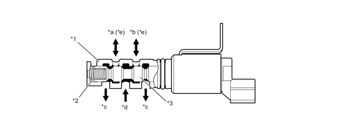
*1 Sleeve *2 Spring *3 Spool Valve - - *a To VVT-i Controller (Advance Side) *b To VVT-i Controller (Retard Side) *c Drain *d Oil Pressure *e On the exhaust side oil control valve, the advance and retard sides are reversed. - -
-
-
-
Operation
-
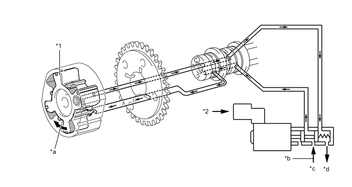
Advance
-
When the camshaft timing oil control valve is positioned as illustrated below by the advance signals from the ECM, the resultant oil pressure is applied to the timing advance side vane chamber to rotate the camshaft in the timing advance direction.
Figure 9. Intake Side
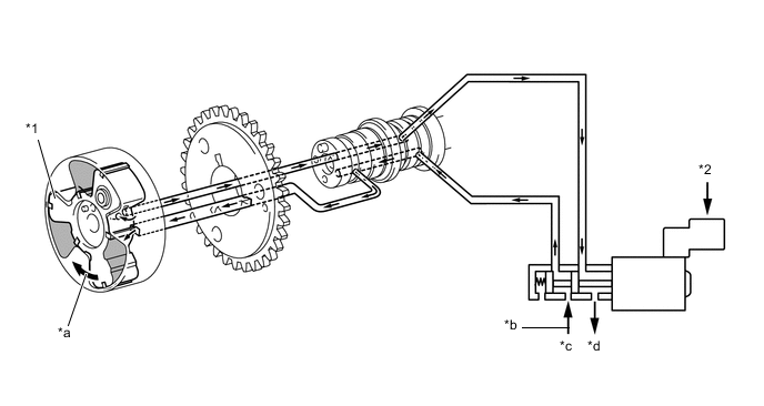
*1 Vane *2 ECM *a Rotation Direction *b Oil Pressure *c In *d Drain Figure 10. Exhaust Side
*1 Vane *2 ECM *a Rotation Direction *b Oil Pressure *c In *d Drain
-
-
Retard
-
When the camshaft timing oil control valve is positioned as illustrated below by the retard signals from the ECM, the resultant oil pressure is applied to the timing retard side vane chamber to rotate the camshaft in the timing retard direction.
Figure 11. Intake Side
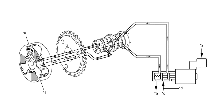
*1 Vane *2 ECM *a Rotation Direction *b Drain *c In *d Oil Pressure Figure 12. Exhaust Side
*1 Vane *2 ECM *a Rotation Direction *b Drain *c In *d Oil Pressure
-
-
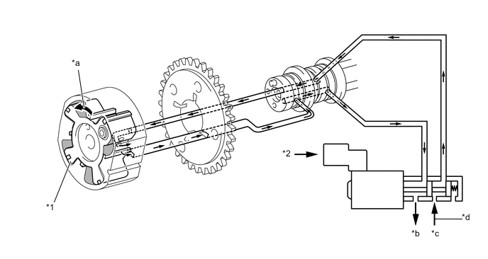
Hold
-
After reaching the target timing, the engine valve timing is maintained by keeping the camshaft timing oil control valve in the neutral position unless the engine operating conditions change.This maintains the engine valve timing at the desired target position by preventing the engine oil from running out of the oil control valve.
-
-
-
-
Acoustic Control Induction System (ACIS)
-
General
-
The ACIS is uses a bulkhead to divide the intake manifold into two stages, with an intake air control valve in the bulkhead being opened and closed to vary the effective length of the intake manifold in accordance with the engine speed and throttle valve opening angle. This increases the power output in all ranges from low to high speed.
Figure 13. System Diagram
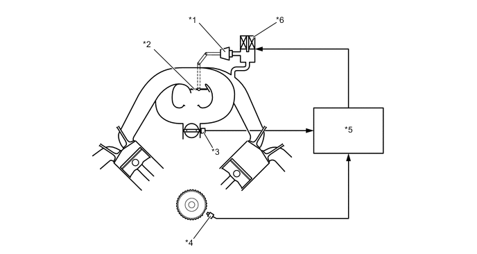
*1 ACIS Actuator *2 Intake Air Control Valve *3 Throttle Position Sensor *4 Crank Position Sensor *5 ECM *6 VSV (for ACIS)
-
-
Intake Air Control Valve and ACIS Actuator
-
The intake air control valve and ACIS actuator are integrated with the intake manifold. This valve opens and closes to change the effective length of the intake manifold in two stages.
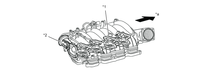
*1 Intake Air Control Valve *2 ACIS Actuator *a Front - -
-
-
Operation
-
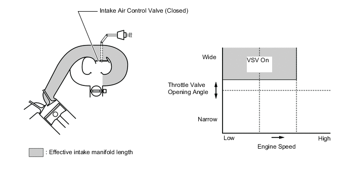
When the Intake Control Valve Closes (VSV On)
-
The ECM activates the VSV so that the negative pressure acts on the diaphragm chamber of the actuator. This closes the control valve to match the longer pulsation cycle. As a result, the effective length of the intake manifold is lengthened and the intake efficiency in the low-to-medium engine speed range under heavy load is improved due to the dynamic effect of the intake air, thereby increasing the power output.
-
-
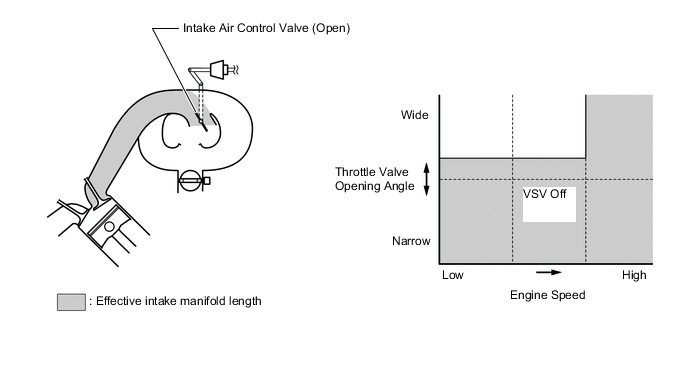
When the Intake Control Valve Opens (VSV Off)
-
The ECM deactivates the VSV so that atmospheric air is led into the diaphragm chamber of the actuator. This opens the control valve to match the shorter pulsation cycle. When the control valve is open, the effective length of the intake manifold is shortened and peak intake efficiency is shifted. This benefits the low, medium and high engine speed ranges at low loads and the high engine speed range under heavy load, thus providing greater output at high engine speeds.
-
-
-
-
Fuel Pump Control
-
General
-
In this vehicle, there are 2 types of fuel pump control. The fuel pump is controlled to an optimum speed to match the engine operating conditions, and the fuel pump operation is cut when the SRS airbags deploy.
-
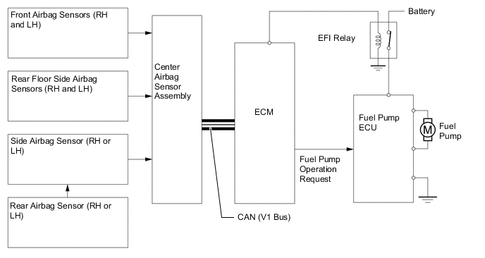
The ECM transmits a fuel pump operation request signal to the fuel pump ECU that corresponds to the engine operating conditions. The fuel pump ECU receives this request signal and controls the fuel pump speed. As a result, under light engine loads, fuel pump speed is kept low to reduce electric power loss.
-
A fuel cut control is used to stop the fuel pump when any of the SRS airbags deploy. In this control, if an airbag deployment signal from the center airbag sensor assembly is detected by the ECM, the ECM will turn OFF the EFI relay. As a result, the power supply to fuel pump ECU is stopped, causing the fuel pump to stop operating. After the fuel cut control has been activated, turning the power source from OFF to IG-ON cancels the fuel cut control, and the engine can be restarted.
Figure 14. System Diagram
-
-
-
-
Air Injection System
-
General
-
To ensure the proper warm-up performance of the Three-Way Catalytic converters (TWCs) after starting a cold engine, an air injection system is used.
-
For this system, each of the bank 2 (right bank) and bank 1 (left bank) has an air pump, air injection control driver, air switching valve, and air pressure sensor. Control of the right bank and left bank is performed independently. Two pumps are used to increase the amount of air supplied, shortening the catalyst warm-up time.
-
The ECM estimates the amount of air injected to the TWCs based on signals from the air flow meter in order to regulate the air injection time.
-
Air is injected under the following conditions.
Operation Conditions Engine Coolant Temperature 5°C to 45°C (41°F to 113°F) Intake Air Temperature 5°C (41°F) or more Figure 15. System Diagram
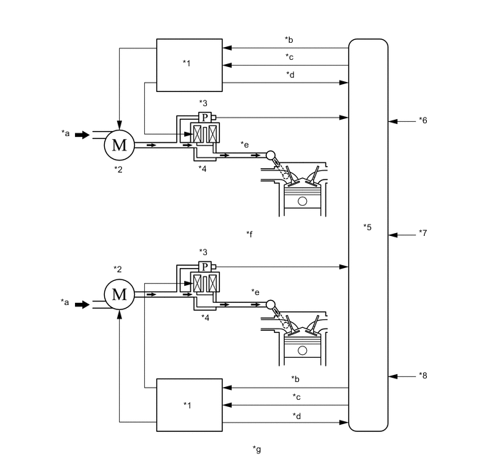
*1 Air Injection Control Driver *2 Air Pump *3 Air Pressure Sensor *4 Air Switching Valve *5 ECM *6 Engine Coolant Temperature Sensor *7 Air Flow Meter *8 Intake Air Temperature Sensor *a Air *b Pump Actuation Request *c Valve Actuation Request *d Diagnosis Signal *e To Exhaust Manifold *f Bank 2 (Right Bank) *g Bank 1 (Left Bank) - -
-
-
-
Construction and Operation
-
Air Pump
-
Each air pump consists of a DC motor, an impeller and an air filter.
-
The air pump supplies air into an air injection control valve using its impeller.
-
The air filter is maintenance-free.
-
The structure and function of the air pumps for the bank 1 and bank 2 are basically the same.
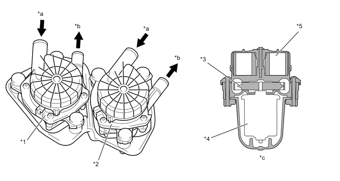
*1 Air Pump (Bank 2) *2 Air Pump (Bank 1) *3 Impeller *4 DC Motor *5 Air Filter - - *a Air In *b Air Out *c Cross Section - - -
-
Air Switching Valve
-
The air switching valve is operated by a solenoid coil to control air injection and prevent back-flow of exhaust gas. Opening timing of the valve is synchronized with the operation timing of the air pump.
-
An air pressure sensor is built into the corresponding air switching valve.
-
The structure and function of the air switching valves for the bank 1 and bank 2 are basically the same.
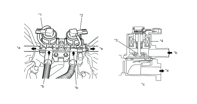
*1 Air Switching Valve (Bank 2) *2 Air Switching Valve (Bank 1) *3 Valve *4 Solenoid Coil *a Air Out *b Air In *c Cross Section (for Bank 1) - -
-
-
Air Pressure Sensor
-
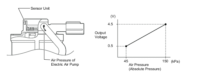
The air pressure sensor consists of a semiconductor, which has a silicon chip that changes its electrical resistance when pressure is applied to it. The sensor converts the pressure into an electrical signal, and sends it to the ECM in an amplified form.
-
The structure and function of the air pressure sensors for the bank 1 and bank 2 are basically the same.
-
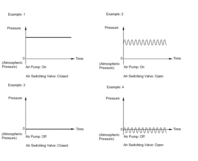
The ECM detects operation of the air injection system based on signals from the air pressure sensor as follows:
-
When the air pump is on and the air switching valve is closed, the pressure is stable.
-
When the air pump is on and the air switching valve is open, the pressure drops slightly and becomes unstable because of exhaust pulses.
-
When the air pump is off and the air switching valve is closed, the pressure remains at atmospheric pressure.
-
When the air pump is off and air switching valve is open, the pressure drops below atmospheric pressure and becomes unstable because of exhaust pulses.
-
-
Air Injection Control Driver
-
A semiconductor type air injection control driver is used. Activated by the ECM, this driver actuates the air pump and the air switching valve.
-
The air injection control driver also detects failures in the input and output circuits of the air injection driver and transmits the failure status to the ECM via duty cycle signals.
-
The basic functions of the air injection control drivers for the bank 1 and bank 2 are the same. The following system chart shows the bank 1 (left bank).
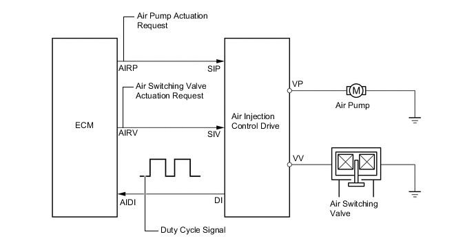
DI Terminal Output Condition AIRP AIRV Output (Duty Cycle Signal) Open circuit in line between AIDI and DI terminals. - - 
Failure in line between ECM terminals and air injection control driver. - - 
Output failure at air injection control driver. (Failure in air pump actuation circuit) - - 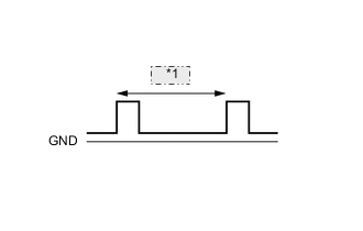
*1 200 ms Output failure at air injection control driver. (Failure in air switching valve actuation circuit) - - 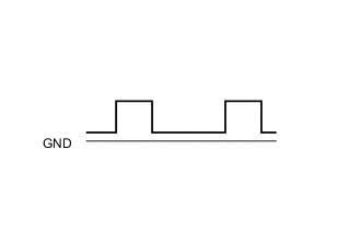
Overheat failure of air injection control driver. - - 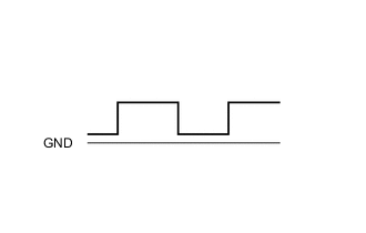
Normal On On 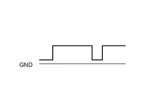
Off Off On Off Off On
-
-
-
-
Starter Control (Cranking Hold Function)
-
General
-
Once the engine switch is pressed, this function continues to operate the starter until the engine has started, provided that the brake pedal is depressed. This prevents starting failure and the engine from being cranked after it has started.
-
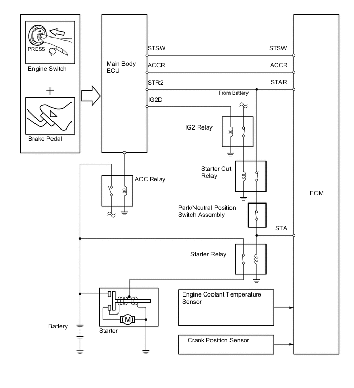
When the ECM detects a start signal from the main body ECU, this system monitors the engine speed (NE signal) and continues to operate the starter until it has determined that the engine has started. Furthermore, even if the ECM detects a start signal from the main body ECU, this system will not operate the starter if the ECM has determined that the engine has already started.
Figure 16. System Diagram
-
-
Operation
-
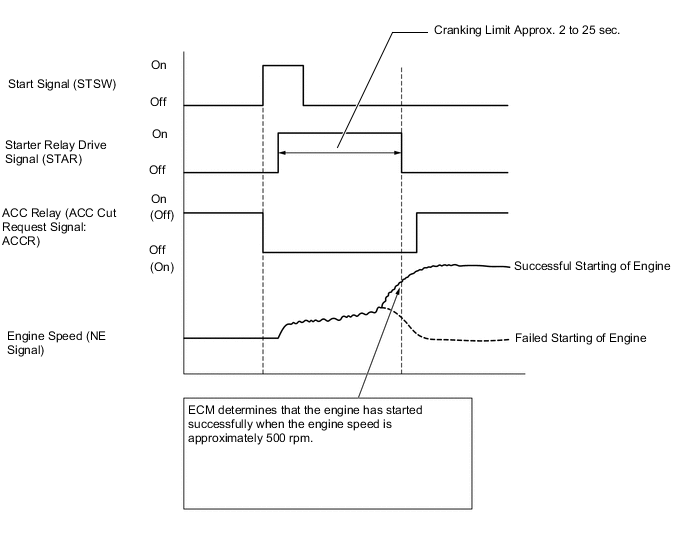
As indicated in the timing chart below, when the ECM detects an STSW signal (start signal) from the main body ECU, the ECM outputs a STAR signal (starter relay drive signal) through the starter cut relay to the starter relay and actuates the starter. The ECM also outputs an ACCR signal (ACC cut request signal) to the main body ECU. Thus, the main body ECU will not energize the ACC relay.
-
After the starter operates and the engine speed becomes higher than approximately 500 rpm, the ECM determines that the engine has started and stops the output of the STAR signal to the starter relay and the output of the ACCR signal to the main body ECU. Thus, the starter operation stops and the main body ECU energizes the ACC relay.
-
If the engine has any failure and does not start, the starter operates as long as its maximum continuous operation time and stops automatically. The maximum continuous operation time is approximately 2 seconds through 25 seconds depending on the engine coolant temperature condition. When the engine coolant temperature is extremely low, it is approximately 25 seconds and when the engine is warmed up sufficiently, it is approximately 2 seconds.
-
This system cuts off the current that powers the accessories while the engine is cranking to prevent the accessory illumination from operating intermittently due to the unstable voltage that is associated with the cranking of the engine.
-
This system has the following protection features:
-
While the engine is running normally, the starter does not operate.
-
Even if the driver keeps pressing the engine switch, the ECM stops the output of the STAR and ACCR signals when the engine speed becomes higher than 1200 rpm. Thus, the starter operation stops and the main body ECU energizes the ACC relay.
-
In case the driver keeps pressing the engine switch and the engine does not start, the ECM stops the output of the STAR and ACCR signals after 30 seconds have elapsed. Thus, the starter operation stops and the main body ECU energizes the ACC relay.
-
In case the ECM cannot detect an engine speed signal while the starter is operating, the ECM will immediately stop the output of the STAR and ACCR signals. Thus, the starter operation stops and the main body ECU energizes the ACC relay.
Figure 17. Timing Chart
-
-
-
-
Diagnosis
-
When the ECM detects a malfunction, it makes a diagnosis and memorizes the failed section. Furthermore, the Malfunction Indicator Lamp (MIL) in the combination meter illuminates or blinks to inform the driver.
-
The ECM will also store the Diagnostic Trouble Code (DTC) of the malfunctions. The DTC can be accessed by using the Global TechStream (GTS).
-
For details, refer to the Repair Manual.
Tech Tips
To clear the DTC that is stored in the ECM, use the Global TechStream (GTS), disconnect the battery terminal or remove the EFI MAIN fuse and ETCS fuse for 1 minute or longer.
-
-
Fail-safe
-
When a malfunction is detected at any of the sensors, there is a possibility of an engine or other malfunction occurring if the ECM were to continue to control the engine control system in the normal way. To prevent such a problem, the fail-safe function of the ECM either relies on the data stored in memory to allow the engine control system to continue operating, or stops the engine if a hazard is anticipated. For details, refer to the Repair Manual.
-