3UR-FE ENGINE
-
General
-
A fuel cut control is used to stop the fuel pump when SRS airbags deploy in a frontal or side collision.
-
Compact 12-hole type fuel injectors are used to improve the atomization of fuel.
-
Fuel delivery pipes formed from stamped steel, which has a pulsation damper function, are used.
-
Quick connectors are used to connect the fuel lines for ease of serviceability.
-
The dual fuel tank which is comprised of a fuel tank and fuel sub tank is provided.*1
-
A multi-layer plastic fuel tank is used.*2
-
A multi-layer plastic fuel sub tank is used.*1
-
*1: Models with dual fuel tank
-
*2: Except models with dual fuel tank
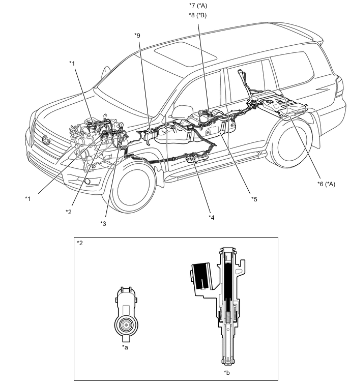
*A Models with Dual Fuel Tank *B Except Models with Dual Fuel Tank *1 Fuel Delivery Pipe *2 Fuel Injector *3 Quick Connector *4 Fuel Filter *5 Fuel Tank *6 Fuel Sub Tank *7 Fuel Pump Assembly
-
Fuel Pump
-
Fuel Sender Gauge
-
Jet Pump
*8 Fuel Pump Assembly
-
Fuel Pump
-
Fuel Sender Gauge
*9 Chalcoal Canister - - *a View from Bottom Side *b Fuel Injector Cross Section -
-
-
Delivery Pipe
-
Fuel delivery pipes formed from stamped steel are used to deliver fuel to the fuel injectors.
-
An inner pipe inside the delivery pipe is used to absorb fuel pulsations. This eliminates the use of the pulsation damper provided on conventional models, making the fuel system more compact and lightweight. When the fuel pulsates, the shape of the inner pipe changes with the pulsation, thus changing the internal capacity of the delivery pipe. This change in capacity absorbs the fuel pulsations.
-
The wiring harnesses that connect to the fuel injectors are combined into a single strand at each bank. Furthermore, they each connect to the engine harness at a single connector for improved serviceability.
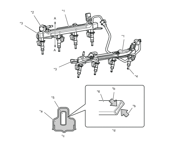
*1 Wiring Harness *2 Fuel Pressure Regulator *3 Fuel Delivery Pipe *4 Fuel Injector *5 Inner Pipe *6 Inner Pipe (For Absorbing Pulsation) *a Fuel *b Fuel Pressure *c A - A Cross Section (Delivery Pipe) *d Movement of Inner Pipe when Absorbing Pulsation
-
-
Fuel Tank
-
General
-
The multi-layer plastic fuel tank consists of 6 layers of 4 types of materials, one of which is a recyclable material to address environmental concerns.
-
A jet pump, which automatically transfers fuel from the fuel sub tank to the fuel tank, is provided in the fuel tank on models with a dual fuel tank.
Figure 1. Cross Section of Fuel Tank

*1 Adhesive *2 High Density Polyethylene *3 Recyclable Material *4 Ethylene Vinyl Alcohol Copolymer *a Interior of Fuel Tank *b Exterior of Fuel Tank Tech Tips
A drain mark has been provided at the lowest position of the fuel tank. When dismantling (scraping) the vehicle, drain fuel by drilling holes at the drain mark.
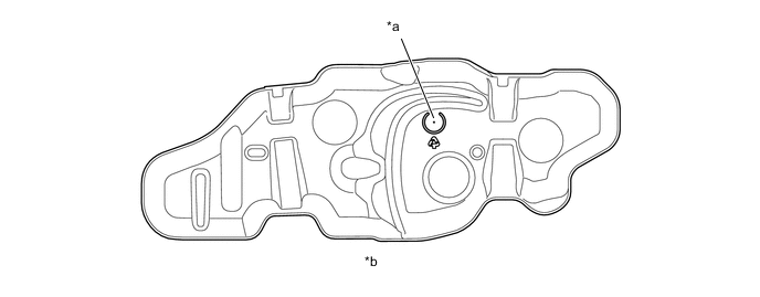
*a Drain Mark *b View from Bottom Side
-
-
Construction of Dual Fuel Tank
-
General
-
A jet pump is provided in the fuel tank in order to automatically transfer fuel from the fuel sub tank to the fuel tank.
-
For the fuel filler pipe, the structure that is united directly beneath the fuel inlet and forked into two in the middle is used in its configuration. Therefore, the driver can refuel without the need to distinguish the fuel tank from the fuel sub tank.
Figure 2. System Diagram
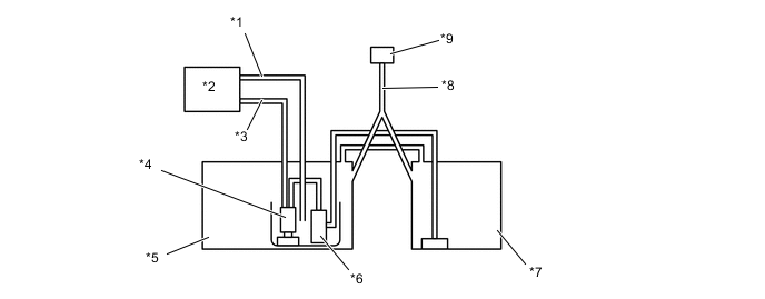
*1 Return Tube *2 Engine *3 Main Tube *4 Fuel Pump *5 Fuel Tank *6 Jet Pump *7 Fuel Sub Tank *8 Fuel Filler Pipe *9 Fuel Inlet - -
-
-
Fuel Inlet
-
There is only one fuel filler pipe directly below the fuel inlet, which branches into two pipes at a midway point.

*1 Fuel Supply Nozzle *2 Fuel Inlet *3 Fuel Filler Pipe - - *a To Sub Fuel Tank *b To Main Fuel Tank
-
-
Operation
-
The fuel from the fuel pump actuates the jet pump in the fuel tank, in order to draw fuel from the fuel sub tank to the fuel tank.
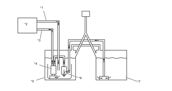
*1 Return Tube *2 Engine *3 Main Tube *4 Fuel Pump *5 Fuel Tank *6 Jet Pump *7 Fuel Sub Tank - - -
The fuel from the fuel pump passes through the orifice in the jet pump and returns to the fuel tank. Because the flow speed of the fuel from the fuel pump increases as it passes through the orifice, a vacuum is created near the exit of the orifice. This vacuum causes the fuel to be drawn from the fuel sub tank to the fuel tank.
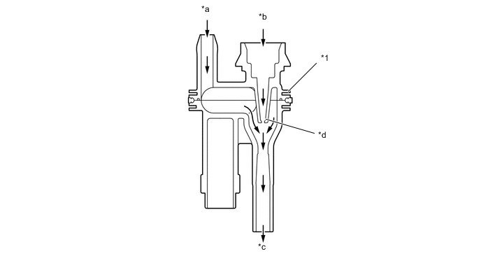
*1 Jet Pump - - *a From Fuel Sub Tank *b From Fuel Pump *c To Fuel Tank *d Orifice
-
-
-