AB60F AUTOMATIC TRANSMISSION
-
GENERAL
-
The electronic control system of the AB60F automatic transmissions consists of the control functions listed below.
Control Function Shift Timing Control The ECM sends current to shift solenoid valves S1, S2, S3, S4 and/or SR based on signals from various sensors, in order to shift the gears. Clutch Pressure Control
-
Controls the pressure that is applied directly to B2 brake and C3 clutch by actuating the linear solenoid valves SL1 and SL2 in accordance with the ECM signals.
-
The shift solenoid valves SLT and SL1 minutely control the clutch pressure in accordance with the engine output and driving conditions.
Line Pressure Optimal Control Actuates the shift solenoid valve SLT to control the line pressure in accordance with information from the ECM and the operating conditions of the transmission. Engine Torque Control Retards the engine ignition timing temporarily to improve shift feeling while upshifts or downshifts occur. Lock-up Timing Control The ECM sends current to the shift solenoid valve SLU based on signals from various sensors and engages or disengages the lock-up clutch. Flex Lock-up Clutch Control Controls the shift solenoid valve SLU, provides an intermediate mode for when the lock-up clutch is between ON and OFF, increasing the operating range of the lock-up clutch to improve fuel economy. Powertrain Cooperative Controls both the shift control and engine output control in an integrated way, achieving excellent shift characteristics and drivability. Coast Downshift Control To prevent engine speed from decreasing and thereby maintain fuel cut, the ECM performs downshifts before fuel cut ends. AI (Artificial Intelligence) -SHIFT Control Based on the signals from various sensors, the ECM determines the road conditions and the intention of the driver. While the pattern select switch is in POWER, the shift pattern is biased toward sporty driving. Thus, an appropriate shift pattern is automatically determined, improving drivability. Multi-mode Automatic Transmission
-
The ECM appropriately controls the automatic transmission in accordance with the range position selected while the shift lever is in the S mode position.
-
When the shift lever is in D, the driver can select a desired shift range using the shift paddle switch (transmission shift switch assembly).*
"R" to "D" Squat Control When the shift lever is shifted from R to D position, the 3rd gear is temporarily engaged before the 1st gear to reduce vehicle squat. "N" to "D" Squat Control When the shift lever is shifted from N to D position, the 2nd gear is temporarily engaged before the 1st gear to reduce vehicle squat. 2nd Start Control Enabling the vehicle to start off in the 2nd gear and thus make it easy to start off snowy, sandy or muddy terrain. Diagnosis When the ECM detects a malfunction, the ECM records the malfunction and memorizes the information that relates to the fault. Fail-safe If a malfunction is detected in the sensors or solenoids, the ECM effects fail-safe control to prevent the vehicle's drivability from being affected significantly. *: Models with shift paddle switch (transmission shift switch assembly)
-
-
-
CONSTRUCTION
-
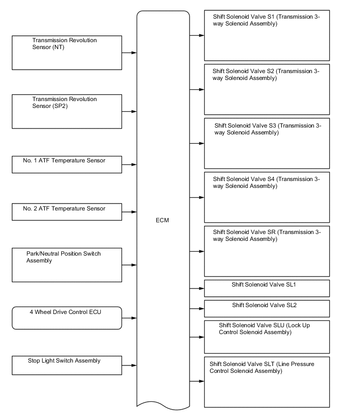
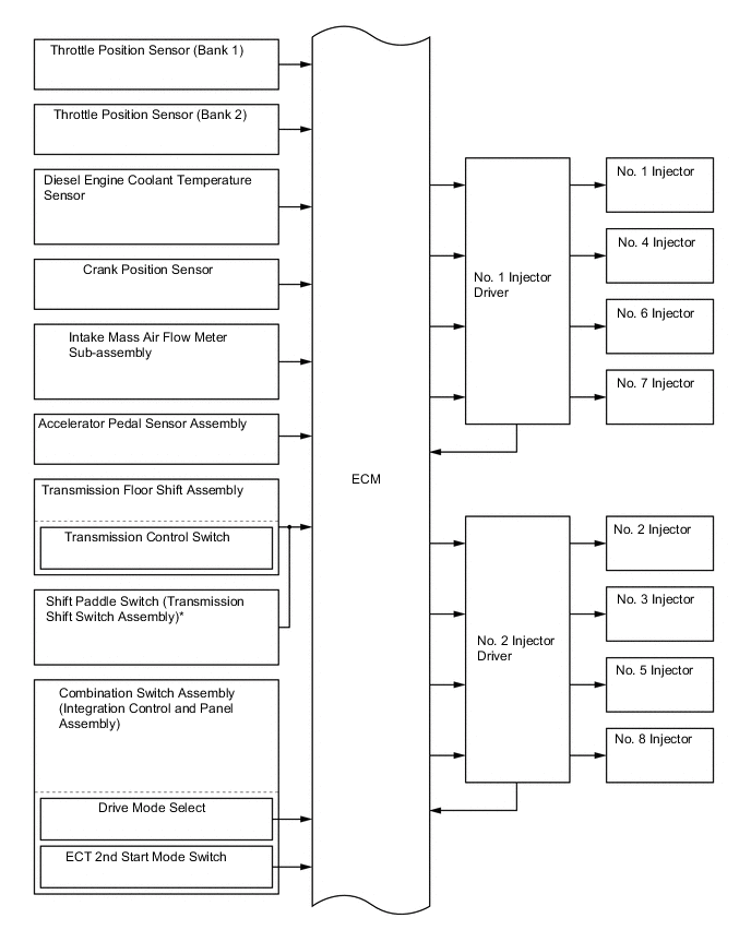
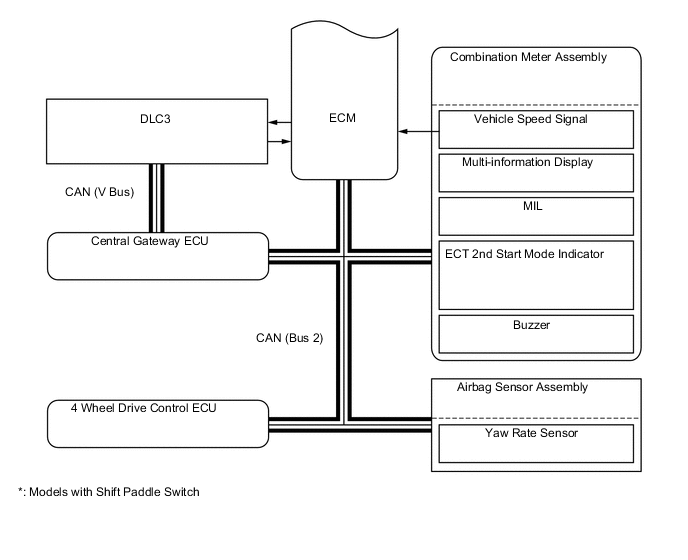
The configurations of the electronic control system for the AB60F automatic transmission is as shown in the following chart.
-
-
LAYOUT OF MAIN COMPONENTS
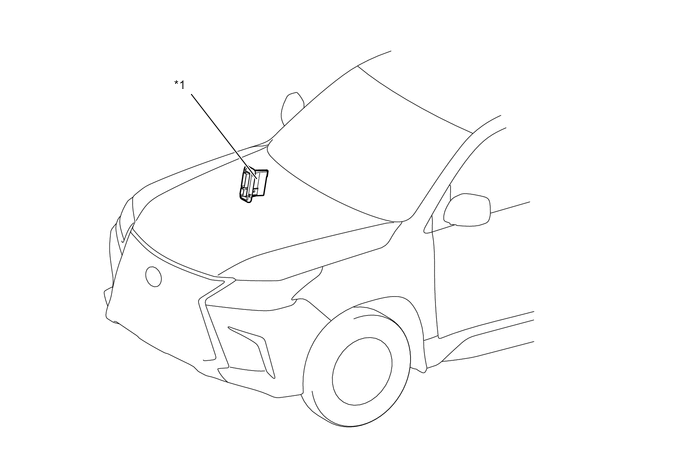
*1 ECM - - 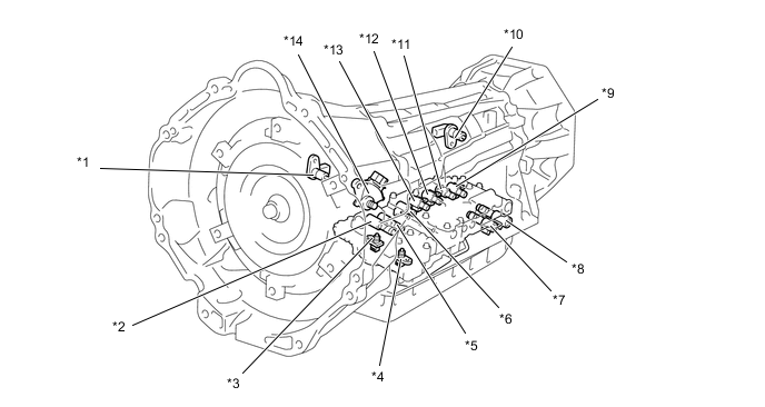
*1 Transmission Revolution Sensor (NT) *2 Shift Solenoid Valve SLT (Line Pressure Control Solenoid Assembly) *3 No. 2 ATF Temperature Sensor *4 No. 1 ATF Temperature Sensor *5 Shift Solenoid Valve SL1 *6 Shift Solenoid Valve SR (Transmission 3-way Solenoid Assembly) *7 Shift Solenoid Valve SL2 *8 Shift Solenoid Valve SLU (Lock Up Control Solenoid Assembly) *9 Shift Solenoid Valve S3 (Transmission 3-way Solenoid Assembly) *10 Transmission Revolution Sensor (SP2) *11 Shift Solenoid Valve S2 (Transmission 3-way Solenoid Assembly) *12 Shift Solenoid Valve S4 (Transmission 3-way Solenoid Assembly) *13 Shift Solenoid Valve S1 (Transmission 3-way Solenoid Assembly) *14 Park/Neutral Position Switch Assembly 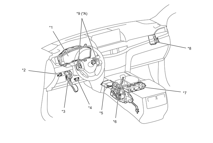
*A Models with Shift Paddle Switch (Transmission Shift Switch Assembly) - - *1 Combination Meter Assembly
-
ECT 2nd Start Mode Indicator Light
-
MIL
-
Multi-Information Display
-
Buzzer
*2 Stop Light Switch Assembly *3 Accelerator Pedal Sensor Assembly *4 DLC3 *5 Air Bag Sensor Assembly
-
Yaw Rate Sensor
*6 Transmission Floor Shift Assembly
-
Transmission Control Switch
*7 Combination Switch Assembly (Integration Control and Panel Assembly)
-
ECT 2nd Start Mode Switch
-
Drive Mode Select
*8 4 Wheel Drive Control ECU *9 Shift Paddle Switch (Transmission Shift Switch Assembly) - - -
-
CONSTRUCTION AND OPERATION OF MAIN COMPONENTS
-
No. 1 and No. 2 ATF Temperature Sensor
-
No. 1 ATF temperature sensor is used for hydraulic pressure control. This sensor is used for revision of the pressure that is used to apply clutches and brakes in the transmission. This helps to ensure smooth shift quality.
-
No. 2 ATF temperature sensor is used as a basis for modifying the ECT shift timing control when the ATF temperature is high. It is also used for the ATF temperature warning light.
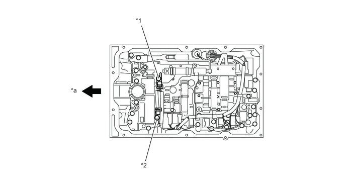
*1 No. 1 ATF Temperature Sensor *2 No. 2 ATF Temperature Sensor *a Front - -
-
-
Transmission Revolution Sensor
-
The AB60F automatic transmissions use a transmission revolution sensor (NT) and transmission revolution sensor (SP2). Thus, the ECM can detect the timing of the shifting of the gears and appropriately control the engine torque and hydraulic pressure in response to various conditions.
-
These transmission revolution sensors are the pick-up coil type.
-
The transmission revolution sensor (NT) detects the input speed of the transmission. The clutch drum is used as the timing rotor for this sensor.
-
The transmission revolution sensor (SP2) detects the speed of the output shaft. The parking gear on the rear planetary gear is used as the timing rotor for this sensor.
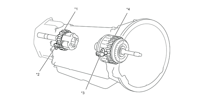
*1 Parking Gear (Timing Rotor) *2 Transmission Revolution Sensor (SP2) *3 Transmission Revolution Sensor (NT) *4 C3 Clutch Drum (Timing Rotor) -
-
-
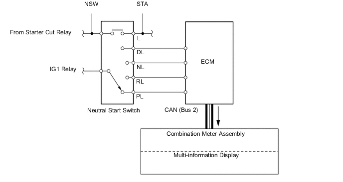
Park/Neutral Position Switch
-
The park/neutral position switch sends the P, R, N and D position signals to the ECM.
Figure 1. Wiring Diagram
-
-
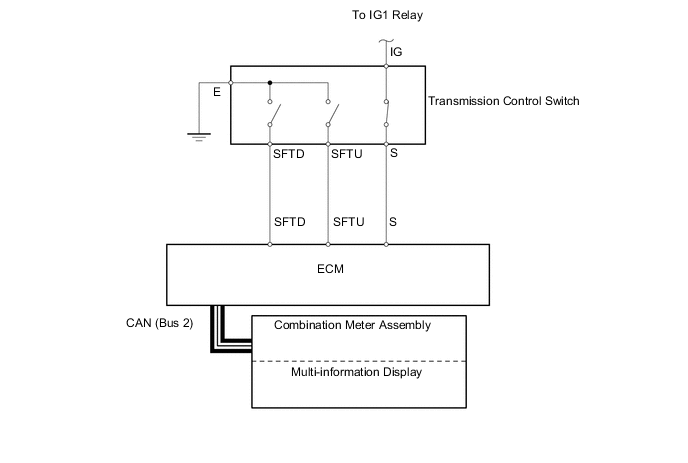
Transmission Control Switch
-
The transmission control switch is installed inside the shift lever assembly to detect the shift lever position and to inform the ECM.
-
The transmission control switch detects whether the shift lever is in the D position or in the S mode position, and detects the operating conditions of the shift lever ("+" position or "-" position) if the S mode is selected, and sends signals to the ECM.
Figure 2. Wiring Diagram
-
-
-
CLUTCH PRESSURE CONTROL
-
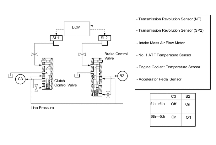
Clutch to Clutch Pressure Control
-
This control is used for shifting from 5th to 6th gear and from 6th to 5th gear.
-
The ECM actuates shift solenoid valves SL1 and SL2 in accordance with various signals. The output from these solenoid valves acts directly on control valves B2 and C3 in order to regulate the line pressure that acts on the B2 brake and C3 clutch.
-
As a result, high response and excellent shift characteristics have been realized.
-
-
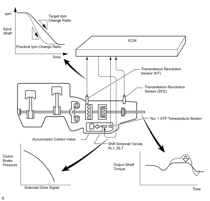
Clutch Pressure Optimal Control
-
The ECM monitors the signals from various types of sensors, such as the input speed sensor, allowing shift solenoid valves SLT and SL1 to minutely control the clutch pressure in accordance with engine output and driving conditions. As a result, smooth shift characteristics are realized.
-
-
-
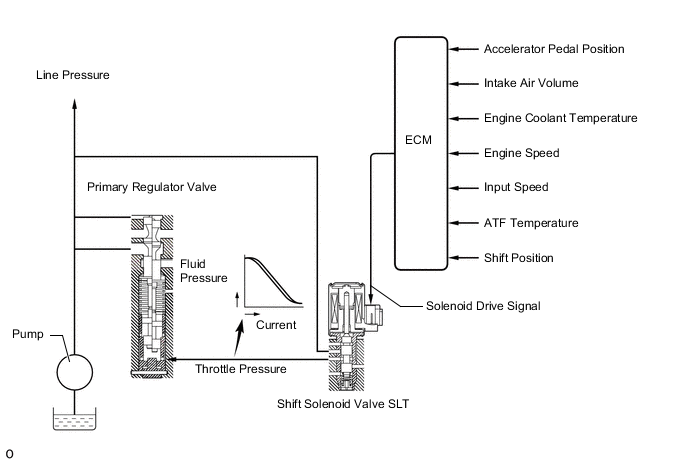
LINE PRESSURE OPTIMAL CONTROL
-
Through the use of the shift solenoid valve SLT, the line pressure is optimally controlled in accordance with the engine torque information, as well as with the internal operating conditions of the torque converter clutch and the transmission.
-
Accordingly, the line pressure can be controlled minutely in accordance with the engine output, traveling condition, and ATF temperature, thus realizing smooth shift characteristics and optimizing the workload of the oil pump (reducing unnecessary parasitic losses).
-
-
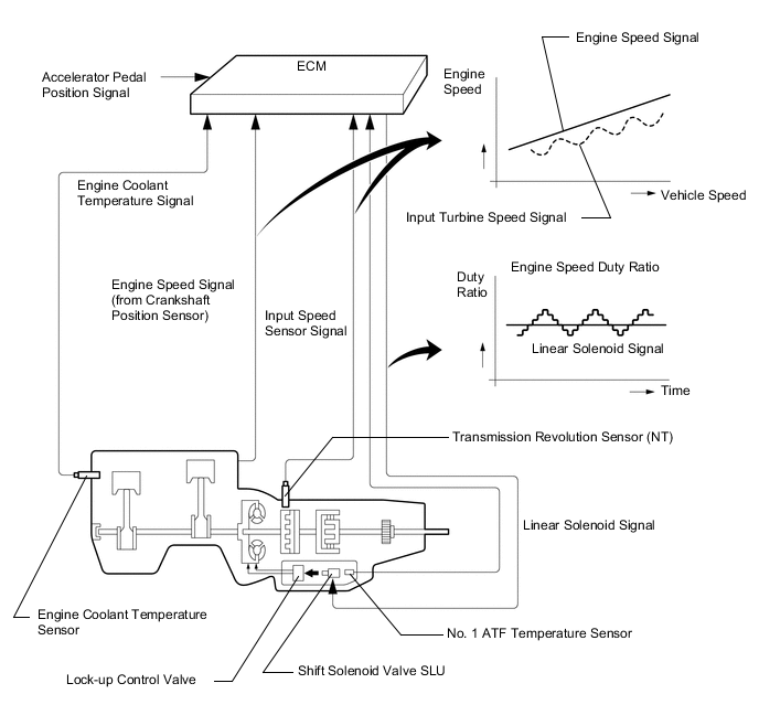
LOCK-UP TIMING CONTROL
-
The ECM operates lock-up timing control in order to improve fuel economy performance.
Figure 3. Lock-up Timing in D Position or S6 Range

Lock-up Operation Gears in Each Range Position or Range D, D6*1, S6 D5*1, S5 D4*1, S4 Gear 1st X X X 2nd X X X 3rd X X X 4th X*2 X*2 ○ 5th ○ ○ - 6th ○ - - ○: Available
x: Not available
-: Not applicable
*1: Models with shift paddle switch (transmission shift switch assembly)
*2: Lock-up operation is performed when the 4th gear is help during the AI-SHIFT control or the cruise control.
-
-
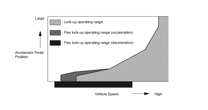
FLEX LOCK-UP CLUTCH CONTROL
-
During acceleration, partial control of the power transmission between the lock-up clutch and torque converter greatly boosts transmission efficiency in accordance with the driving conditions, improving fuel economy.
-
Even when the vehicle is decelerating (the accelerator pedal is released), flex lock-up clutch control operates. As a result, the fuel-cut area is expanded and fuel economy is improved.
-
By allowing flex lock-up clutch control to continue operating during gearshifts, smooth torque transmission is obtained. As a result, fuel economy and drivability are improved.
Flex Lock-up Operation Gears in Each Range Position or Range D, D6*1, S6 D5*1, S5 D4*1, S4 Gear 1st X X X 2nd X X X 3rd ○ ○ ○ 4th ○*2 ○*2 ○*2 5th ○*2 ○*2 - 6th ○*2 - - ○: Available
x: Not available
-: Not applicable
*1: Models with shift paddle switch (transmission shift switch assembly)
*2: Flex Lock-up also operates, when the vehicle is decelerating
-
-
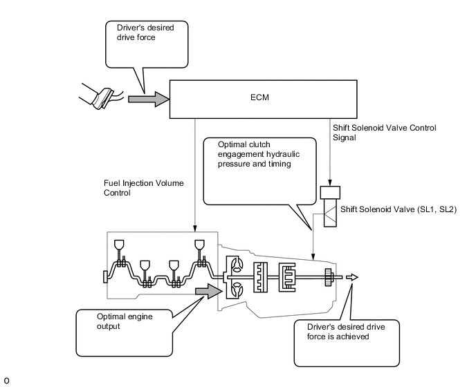
POWERTRAIN COOPERATIVE CONTROL
-
Through cooperative control with fuel injection volume control, and optimally controlled hydraulic pressure to the clutch and brake, excellent response and shift shock reduction have been achieved.
-
-
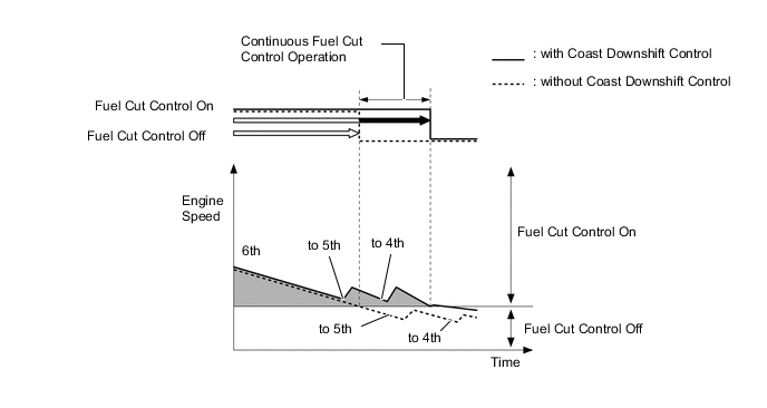
COAST DOWNSHIFT CONTROL
-
As a result of coast downshift control, downshifts are performed to maintain sufficient engine speed to avoid ending fuel cut control. Thus, fuel cut time is extended and fuel economy is achieved.
-
In this control, the transmission downshifts from 6th to 5th and then 5th to 4th before fuel cut control ends when the vehicle is decelerated in the 6th gear, so that fuel cut control continues operating.
-
-
-
AI-SHIFT CONTROL
-
General
-
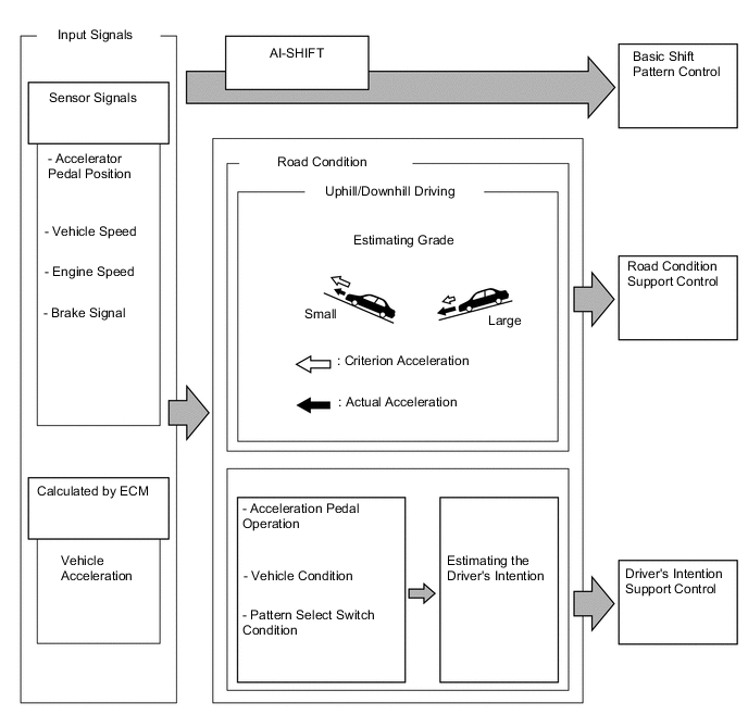
In addition to changing the shift pattern through the pattern select switch, the AI-SHIFT control enables the ECM to estimate the road condition, the driver's intention, and the pattern select switch condition in order to automatically select the optimal shift pattern. As a result, a comfortable ride is realized.
-
AI-SHIFT control is effect only with the shift lever in the D position, based on the accelerator pedal and brake operation data. AI-SHIFT control will be canceled when the driver selects the S mode.
-
-
-
Road Condition Support Control
-
Under road condition support control, the ECM determines whether the vehicle is being driven uphill or downhill based on the accelerator pedal position and the vehicle speed.
-
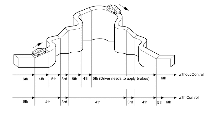
To achieve an optimal drive force while driving uphill, this control prevents the transmission from upshifting to 4th, 5th or 6th gear.
-
To achieve an optimal engine braking effect while driving downhill, this control automatically downshifts the transmission to 5th, 4th or 3rd gear.
-
-
-
Driver's Intention Support Control
-
Driver's intention support control estimates the driver's intention based on the accelerator pedal operation and vehicle condition and selects a shift pattern that is well-suited to each driver.
Control Operation Operate Gear Pattern Select Switch Sudden Accelerator Pedal Depress Control When the driver operates (presses) the accelerator pedal quickly, this control causes the transmission to downshift rapidly to improve acceleration response. 5th to 6th POWER Sudden Accelerator Pedal Release Control When the driver releases the accelerator quickly, this control makes it easy for the transmission to hold the gear, which improves engine braking force and re-acceleration response. 3rd to 5th POWER Sudden Deceleration Downshift Control When the driver decelerates the vehicle suddenly, this control downshifts rapidly, which improves engine braking force and re-acceleration response. 4th to 6th POWER
-
-
-
MULTI-MODE AUTOMATIC TRANSMISSION
-
General
-
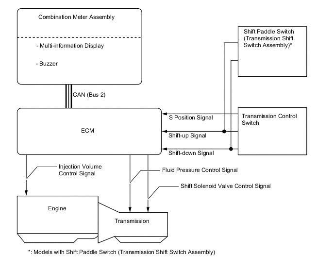
The driver can select the desired gear range by moving the shift lever to "+" (forward) or "-" (backward) while the shift lever is in S. Also, the shift paddle switch (transmission shift switch assembly)* can be used to change the gear range while the driver is holding the steering wheel. Thus, the driver is able to shift gears with a manual-like feel.
-
When the vehicle is being driven at a prescribed speed or higher, any attempt to shift to a lower range by operating the shift lever will not be executed, in order to protect the automatic transmission. In this case, the ECM sounds the buzzer in the combination meter assembly twice to alert the driver.
-
When the shift lever is in D, the driver can momentarily select a desired shift range by operating the shift paddle switch (transmission shift switch assembly)*. Automatic shifting will be reinstated under the following conditions:
-
The vehicle has stopped.
-
The driver continues to push the shift paddle switch (transmission shift switch assembly)* in the "+" direction longer than 1 second.
-
The driver depresses the accelerator pedal longer than a predetermined length of time.
-
*: Models with shift paddle switch (transmission shift switch assembly)
Figure 4. System Diagram
-
-
-
-
FUNCTION
-
Drive Mode Select Function
-
The drive mode can be selected by operating the combination switch assembly (Integration Control and Panel Assembly) (drive mode select or ECT 2nd start mode switch).
-
The selected drive mode will be shown on the multi-information display in the combination meter assembly.
Characteristics of Drive Mode Drive Mode Outline NORMAL Mode Best for easy driving. COMFORT Mode ECO Mode Controls the driving force for superior fuel economy property, compared to NORMAL mode, making it possible low fuel consumption drive. SPORT S Mode When a shift solenoid valve listed at left fails, the current to the failed solenoid valve is cut off.
Optimal for sporty driving through the improved acceleration and responsiveness by changing the shifting points of the transmission from those of the NORMAL mode and controlling the throttle positions.
SPORT S+ Mode ECT 2nd Start Mode Allows the vehicle to start in the 2nd gear for providing an enough traction force at slippery road surfaces such as sands and snow. CUSTOMIZE Mode The CUSTOMIZE mode allows the driver to freely set modes to his/her preferable adjustments in each of the power train control (engine/transmission), chassis control (steering/suspension), and air-conditioning control, in addition to the "ECO," "COMFORT," "NORMAL," "SPORT S," and "SPORT S+" modes provided by default. 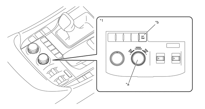
*1 Combination Switch Assembly (Integration Control and Panel Assembly) - - *a Drive Mode Select *b ECT 2nd Start Mode Switch 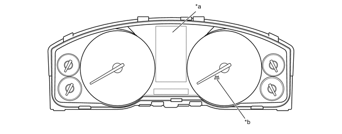
*a Multi-information Display *b ECT 2nd Start Mode Indicator Light
-
-
-
DIAGNOSIS
-
When the ECM detects a malfunction, it makes a diagnosis and memorizes the failed section. Furthermore, the ECM illuminates or blinks the MIL in the combination meter assembly to inform the driver.
-
The ECM will also store the Diagnostic Trouble Codes (DTCs) of the malfunctions. The DTCs can be read by connecting a Global TechStream (GTS) to the DLC3.
-
For details, refer to the Repair Manual.
-
-
FAIL-SAFE
-
The fail-safe function minimizes the loss of operability when an abnormality occurs in a sensor or solenoid.
Fail-safe Control List Malfunction Part Function Transmission Revolution Sensor (NT) When the transmission revolution sensor (NT) malfunctions, shift control is effected using the information from the transmission revolution sensor (SP2) signal.
During a transmission revolution sensor (NT) malfunction, up-shift to the 5th, 6th, AI-SHIFT and flex lock-up clutch control are prohibited.
Transmission Revolution Sensor (SP2) When the transmission revolution sensor (SP2) malfunctions, shift control is effected using the information from the transmission revolution sensor (NT) signal.
When the transmission revolution sensor (SP2) malfunctions, up-shift to the 5th, 6th, AI-SHIFT and flex lock-up clutch control are prohibited.
No. 1 ATF Temperature Sensor When the No. 1 ATF temperature sensor malfunctions, up-shift to the 5th, 6th and flex lock-up clutch control are prohibited. Shift Solenoid Valve S1, S2, S3, S4 and SR When a shift solenoid valve listed at left fails, the current to the failed solenoid valve is cut off.
Shift control is changed to a fail-safe mode to shift gears using the normal shift solenoid valves to allow continued driving. Refer to the table on the next page for an operation example.
Shift Solenoid Valve SL1 and SL2 During a shift solenoid valve SL1 or SL2 malfunction, up-shift to the 5th and 6th and flex lock-up clutch control are prohibited. Shift Solenoid Valve SLU During a shift solenoid valve SLU malfunction, the current to the solenoid valve is stopped. Because this stops lock-up control and flex lock-up control, fuel economy decreases. Shift Solenoid Valve SLT During a shift solenoid valve SLT malfunction, the current to the solenoid valve is stopped. Because this stops line pressure optimal control, the shift shock increases. However, shifting is effected through normal clutch pressure control. Shift Lever or Gear Range Position Shift Solenoid Valve Gear S1 S2 S3 S4 SR SL1 SL2 D, S6 Off On On Off On Off On 1st On On On Off On Off On 2nd On Off On Off On Off On 3rd On Off Off Off On Off On 4th On Off Off On Off On Off 5th On On Off On Off On Off 6th S5 Off On On Off On Off On 1st On On On Off On Off On 2nd On Off On Off On Off On 3rd On Off Off Off On Off On 4th On Off Off On Off On Off 5th S4 Off On On Off On Off On 1st On On On Off On Off On 2nd On Off On Off On Off On 3rd On Off Off Off On Off On 4th S3 Off On On Off On Off On 1st On On On Off On Off On 2nd On Off On Off On Off Off 3rd S2 Off On On Off On Off On 1st On On On On On Off Off 2nd S1 Off On On Off On Off Off 1st Example (Shift Solenoid Valve S1 Malfunction) Shift Lever or Gear Range Position Shift Solenoid Valve Gear S1 S2 S3 S4 SR SL1 SL2 D, S6 X On On Off On Off On 1st X On → Off On → Off Off On Off On 1st → 4th X Off On → Off Off On Off On 3rd → 4th X Off Off Off On Off On 4th X Off Off On Off On Off 5th X On → Off Off On Off On Off N → 5th S5 X On On Off On Off On 1st X On → Off On → Off Off On Off On 1st → 4th X Off On → Off Off On Off On 3rd → 4th X Off Off Off On Off On 4th X Off Off On Off On Off 5th S4 X On On Off On Off On 1st X On → Off On → Off Off On Off On 1st → 4th X Off On → Off Off On Off On 3rd → 4th X Off Off Off On Off On 4th S3 X On On Off On Off On 1st X On → Off On → Off Off On Off On 1st → 4th X Off On → Off Off On Off Off → On 3rd (E/B) → 4th S2 X On On Off On Off On 1st X On → Off On → Off On → Off On Off Off → On 2nd (E/B) → 4th S1 X On On Off On Off Off 1st (E/B) E/B: Engine Braking
-