AB60F AUTOMATIC TRANSMISSION
-
GENERAL
-
A gate type shift lever with boot that uses a transmission control rod is used.
-
The shift control mechanism consists of a transmission floor shift assembly and a floor shift gear shifting rod sub-assembly.
-
The shift lever used is a 5-position (P, R, N, D and S) gate type lever. The gate type shift lever operates on the single-shift operation principle (front-rear and side-to-side). Therefore, it does not require the use of a shift lever button, which is used on a straight type shift lever, and excels in ease of use.
-
A shift lever cap is provided on the shift lock release button to prevent erroneous operation.
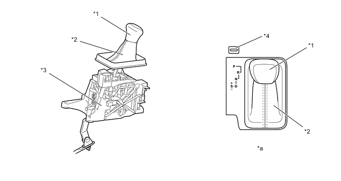
*1 Shift Lever Knob Sub-assembly *2 Shift Boot *3 Transmission Floor Shift Assembly *4 Shift Lever Cap *a Shift Pattern - -
-
-
SHIFT LOCK SYSTEM
-
General
-
The shift lock system prevents the shift lever from being moved to any position other than P, unless the engine switch is turned on (IG) and the brake pedal is depressed. This prevents the vehicle from starting off suddenly.
-
The shift lock system is controlled by the shift lock control ECU, and it has a shift lock function.
-
The shift lock control ECU has a built-in P detection switch to detect the shift lever position, and receives input signals from the stop light switch assembly and engine switch. Upon receiving these signals, the shift lock control ECU turns on the shift lock solenoid assembly in order to release the shift lock.
Figure 1. System Diagram
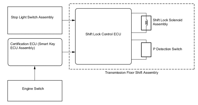
Figure 2. Parts Location
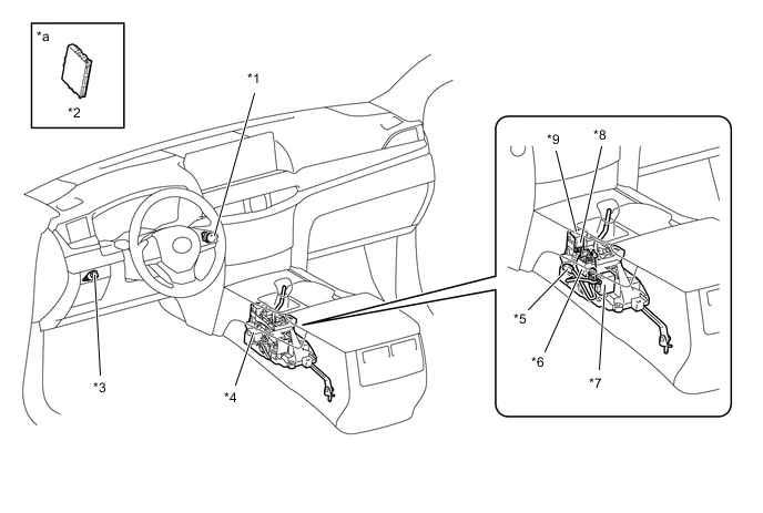
*1 Engine Switch *2 Certification ECU (Smart Key ECU Assembly) *3 Stop Light Switch Assembly *4 Transmission Floor Shift Assembly *5 P Detection Switch *6 Shift Lock Solenoid Assembly *7 Shift Lock Control ECU *8 Shift Lock Release Button *9 Shift Lock Release Button Cap - - *a Refer to the Service Bulletin for the installation position of the part. - -
-
-
-
Function of Main Components Component Function Transmission Floor Shift Assembly Shift Lock Solenoid Assembly Locks the shift lever in P. P Detection Switch Detects when the shift lever is in P. Shift Lock Control ECU Controls the Shift Lock Solenoid assembly and the key interlock solenoid based on signals from each switch. Stop Light Switch Assembly Detects when the brake pedal is depressed. SHIFT LOCK CONTROL
-
SYSTEM CONTROL
-
The shift lock control ECU uses the P detection switch to detect the shift lever position, and receives input signals from the stop light switch assembly and engine switch. Upon receiving these signals, the shift lock control ECU turns on the shift lock solenoid assembly in order to release shift lock.
-
-
FUNCTION
-
Shift Lock Mechanism
-
The shift lock mechanism prevents the shift lever from being moved to any position other than P, unless the engine switch is on (IG), and the brake pedal is depressed. This mechanism helps to prevent unintentional acceleration.
-
A shift lock release button, which manually overrides the shift lock mechanism, is provided.
-
-