1VD-FTV ENGINE
-
General
-
A common-rail system is used in the fuel injection system.
-
3-plunger type (HP4 type) injection or supply pump assembly, which is compact and lightweight, is used.
-
An injector compensation value and a QR code are printed on the injector assembly to realize high-precision control.
-
A fuel filter, in which the fuel filter element alone can be replaced, is used.
-
A fuel filter warning switch is provided in the fuel filter.
-
A recirculation type fuel heater is used.*1
-
2 fuel coolers are used in the fuel return path.*2
-
Quick connectors are used to connect the fuel lines for ease of serviceability.
-
A fuel sub tank sub-assembly is used.*3
-
A fuel pump and jet pump are provided in the fuel tank on models equipped with a fuel sub tank sub-assembly to transfer fuel from the fuel sub tank sub-assembly to the fuel tank sub-assembly.*3
-
A fuel pressure discharge valve is used.*4
-
8 solenoid type injector assemblies are used.*2
-
8 piezo type injector assemblies are used.*4
-
2 exhaust fuel addition injector assemblies are used.*4
-
A fuel feeding pipe for the exhaust fuel addition injector assembly is provided on the injection or supply pump assembly.*4
-
*1: Models with fuel heater
-
*2: Except models compliant with EURO 5 emission regulations
-
*3: Models with dual fuel tank
-
*4: Models compliant with EURO 5 emission regulations
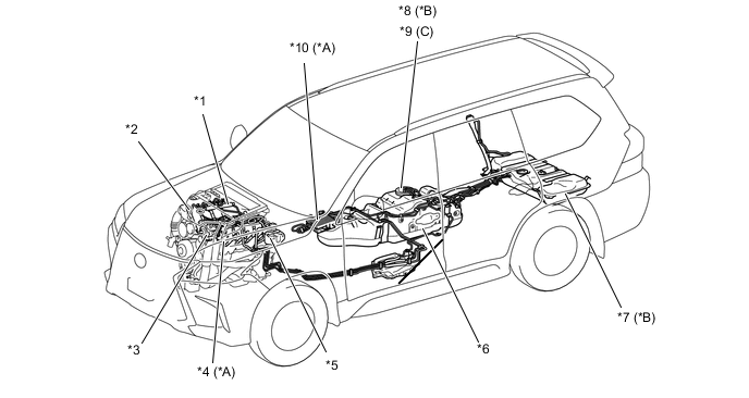
*A Except Models Compliant with EURO 5 Emission Regulations *B Models with Dual Fuel Tank *C Except Models with Dual Fuel Tank - - *1 Common-rail Assembly *2 Injector Assembly *3 Injection or Supply Pump Assembly *4 Fuel Cooler Assembly *5 Fuel Filter *6 Fuel Tank Sub-assembly *7 Fuel Sub Tank Sub-assembly *8 Fuel Suction Tube with Pump and Gauge Assembly
-
Fuel Pump
-
Jet Pump
-
Fuel Sender Gauge
*9 Fuel Suction Tube with Pump and Gauge Assembly
-
Fuel Sender Gauge
*10 Fuel Cooler Assembly Figure 1. Models Compliant with EURO 5 Emission Regulations
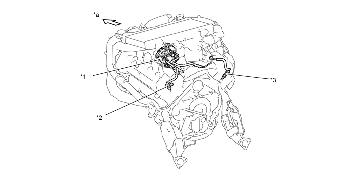
*1 Injection or Supply Pump Assembly *2 Exhaust Fuel Addition Injector Assembly (Bank 2) *3 Exhaust Fuel Addition Injector Assembly (Bank 1) - - *a Front - - -
-
-
Common-rail System
-
Except Models Compliant with EURO 5 Emission Regulations
-
In this system, the high-pressurized fuel that is supplied by the injection or supply pump assembly is stored in the common-rail assembly, and the ECM sends signals to the injector assemblies via the injector driver in order to control the injection timing and injection volume.
Figure 2. Models without Fuel Heater
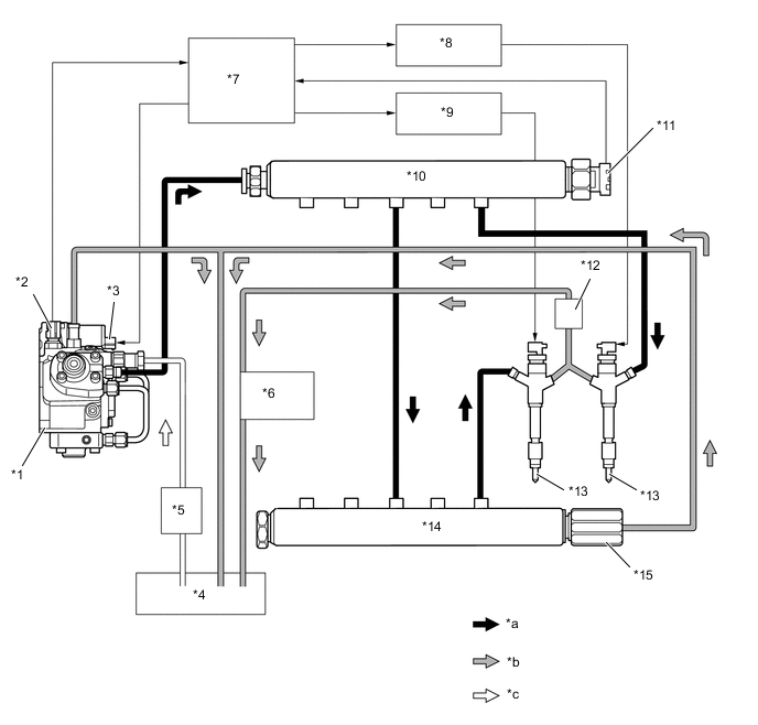
*1 Injection or Supply Pump Assembly *2 Fuel Temperature Sensor *3 SCV *4 Fuel Tank Sub-assembly *5 Fuel Filter *6 Fuel Cooler Assembly (Air-cooled Type) *7 ECM *8 No. 1 Injector Driver *9 No. 2 Injector Driver *10 Common-rail Assembly (RH) *11 Fuel Pressure Sensor *12 Fuel Cooler Assembly (Water-cooled Type) *13 Injector Assembly *14 Common-rail Assembly (LH) *15 Pressure Limiter - - *a High Pressure Fuel *b Return Fuel *c Suctioned Fuel - -
-
-
Models Compliant with EURO 5 Emission Regulations
-
In this system, the high-pressurized fuel that is supplied by the injection or supply pump assembly is stored in the common-rail assembly, and the ECM sends signals to the injector assemblies via the injector driver in order to control the injection timing and injection volume.
-
A common-rail assembly with the fuel pressure discharge valve and piezo type injector assembly with maximum injection pressure of 200 MPa are used to improve driveability and reduce Noise and Vibration (NV).
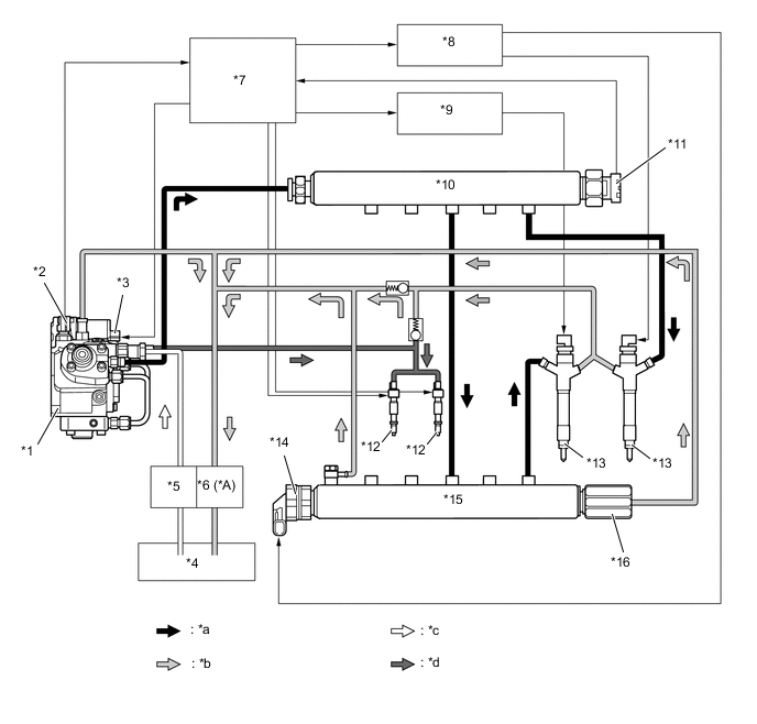
*A Models with Fuel Heater - - *1 Injection or Supply Pump Assembly *2 Fuel Temperature Sensor *3 SCV *4 Fuel Tank Sub-assembly *5 Fuel Filter *6 Fuel Heater *7 ECM *8 No. 1 Injector Driver *9 No. 2 Injector Driver *10 Common-rail Assembly (RH) *11 Fuel Pressure Sensor *12 Exhaust Fuel Addition Injector Assembly *13 Injector Assembly *14 Fuel Pressure Discharge Valve *15 Common-rail Assembly (LH) *16 Pressure Limiter *a High Pressure Fuel *b Return Fuel *c Suctioned Fuel *d Fuel to Exhaust Fuel Addition Injector Assembly
-
-
-
Supply Pump
-
General
-
The injection or supply pump assembly consists of an inner cam (eccentric cam), outer cam (polygon ring), and 3 plungers, Suction Control Valve (SCV), and a feed pump. Each plunger is placed outside of the outer cam.
-
A fuel feeding pipe is provided on the injection or supply pump assembly to supply fuel to the exhaust fuel addition injector assembly. The function, structure and operation are the same as those of the conventional injection or supply pump assembly.*
-
*: Models compliant with EURO 5 emission regulations
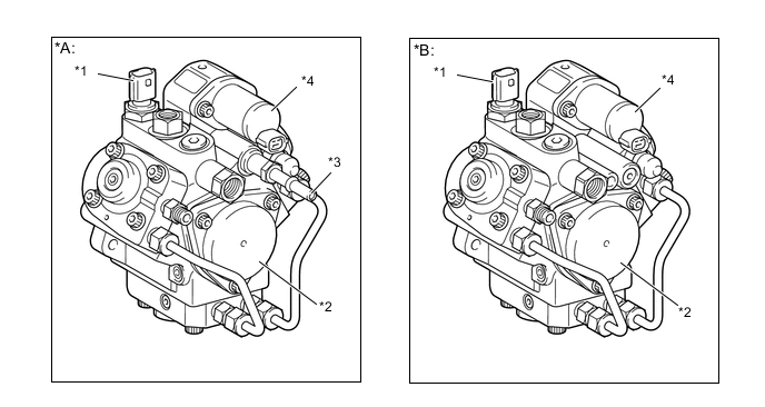
*A Models Compliant with EURO 5 Emission Regulations *B Except Models Compliant with EURO 5 Emission Regulations *1 Fuel Temperature Sensor *2 Feed Pump *3 Fuel Feeding Pipe *4 SCV Figure 3. Injection or Supply Pump Assembly Cross Section
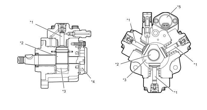
*1 Plunger *2 Inner Cam *3 Outer Cam *4 Feed Pump *5 SCV - -
-
-
Operation
-
Due to the rotation of the inner cam (eccentric cam), the outer cam pushes plunger "A" upward as illustrated below. The force of the spring pulls plungers "B" and "C". As a result, plungers "B" and "C" draw fuel in, and plunger "A" pumps fuel at the same time.
-
The SCV controls the volume of fuel that is drawn into the plungers in accordance with the signals from the ECM.
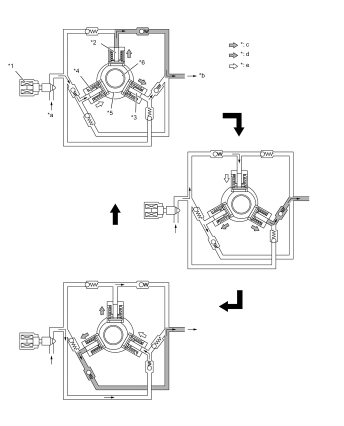
*1 SCV *2 Plunger "A" *3 Plunger "B" *4 Plunger "C" *5 Outer Cam *6 Inner Cam *a Suction *b To Injector Assembly *c Pumping Finish *d Pumping Start *e Suction - -
-
-
-
Common-rail
-
The function of the common-rail assembly is to store the fuel that has been pressurized by the injection or supply pump assembly.
-
The common-rail assembly is provided with a fuel pressure sensor, which detects the fuel pressure in the common-rail assembly, and a pressure limiter that mechanically relieves the pressure in case the internal pressure of the common-rail assembly rises abnormally.
-
Internally, the common-rail assembly contains a main hole and five branch holes that intersect the main hole. Each branch hole functions as an orifice that dampens the fluctuation of the fuel pressure.
-
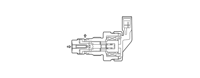
A fuel pressure discharge valve is used.*
-
The fuel pressure discharge valve regulates the fuel pressure within the fuel pressure range normally. In the fuel pressure discharge valve, the plunger opens and closes in accordance with the actuation signals from the injector driver. Thus, it regulates pressure by releasing excess pressure from the common-rail assembly.*
-
*: Models compliant with EURO 5 emission regulations
Figure 4. Except Models Compliant with EURO 5 Emission Regulations
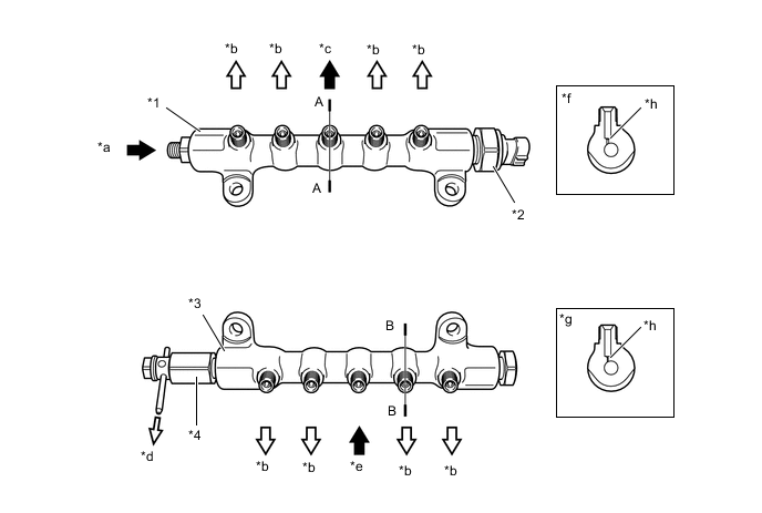
*1 Common-rail Assembly (RH) *2 Fuel Pressure Sensor *3 Common-rail Assembly (LH) *4 Pressure Limiter *a From Injection or Supply Pump Assembly *b To Injector Assembly *c To Common-rail Assembly (LH) *d To Fuel Tank Sub-assembly (Excess Pressure) *e From Common-rail Assembly (RH) *f A - A Cross Section *g B - B Cross Section *h Branch Hole Figure 5. Models Compliant with EURO 5 Emission Regulations
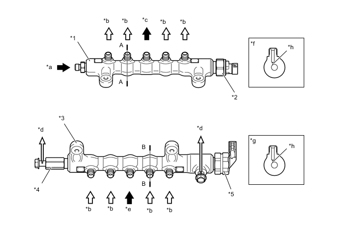
*1 Common-rail Assembly (RH) *2 Fuel Pressure Sensor *3 Common-rail Assembly (LH) *4 Pressure Limiter *5 Fuel Pressure Discharge Valve - - *a From Injection or Supply Pump Assembly *b To Injector Assembly *c To Common-rail Assembly (LH) *d To Fuel Tank Sub-assembly (Excess Pressure) *e From Common-rail Assembly (RH) *f A - A Cross Section *g B - B Cross Section *h Branch Hole Figure 6. Fuel Pressure Discharge Valve Cross Section
-
-
-
Injector
-
Except Models Compliant with EURO 5 Emission Regulations
-
General
-
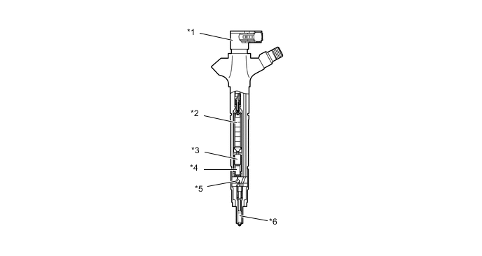
The injector assembly consists of a nozzle needle, piston and solenoid valve.
-
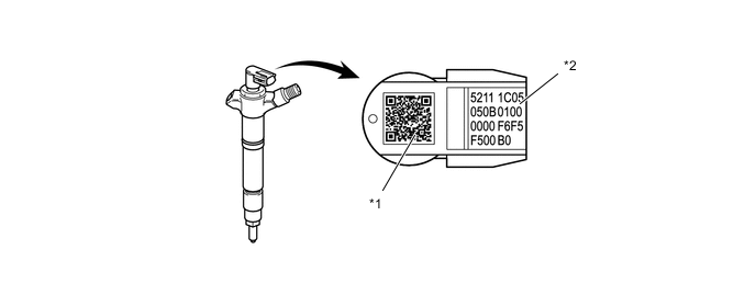
An injector compensation value and QR (Quick Response) code containing encoded characteristics of the injector assembly are printed on each injector assembly.
-
The injector compensation value and QR code contain various pieces of information regarding the injector assembly, such as model code, injection volume correction and injection timing correction values.
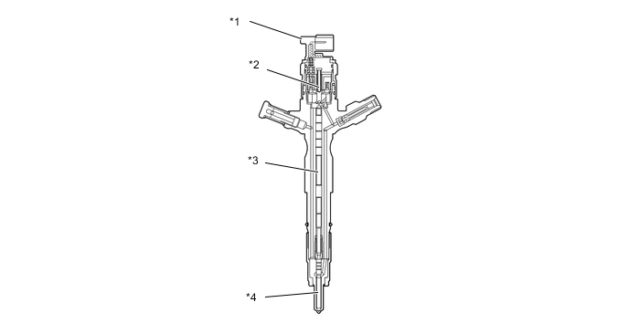
*1 Injector Assembly *2 Solenoid Valve *3 Piston *4 Nozzle Needle
Tech Tips
-
If the ECM is replaced, use the Global TechStream (GTS) and input the injector compensation values of all 8 injector assemblies. If one of the injector assemblies is replaced, input the injector compensation value of the replaced injector assembly. Then, the proper compensation will be made so that the injection volume precision prior to the replacement will remain unchanged. For details, refer to the Repair Manual.
-
The QR code, which requires a special scan tool, is not used at LEXUS dealers.
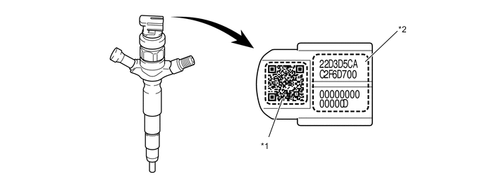
*1 QR Code *2 Injector Compensation Value -
What is Quick Response (QR) Code?:
-
QR code, a matrix symbology consisting of an array of nominally square cells, allows omni-directional, high-speed reading of large amounts of data.
-
QR code encodes many types of date such as numeric, alphanumeric, kanji, kana and binary code. A maximum of 7,089 characters (numeric) can be encoded.
-
QR code (2D code) contains information in the vertical and horizontal direction, whereas a bar code contains data in one direction only. QR code (2D code) holds a considerably greater volume of information than a bar code.
-
-
Operation
-
(A): When electrical current is applied to the solenoid coil, it pulls the solenoid valve up.
-
(B): The orifice of the control chamber opens, allowing the fuel to flow out.
-
(C): The fuel pressure in the control chamber drops.
-
(D): Simultaneously, fuel flows from the orifice to the bottom of the piston and raises the piston up (to enhance response).
-
(E): As a result, the piston raises the nozzle needle to inject fuel.
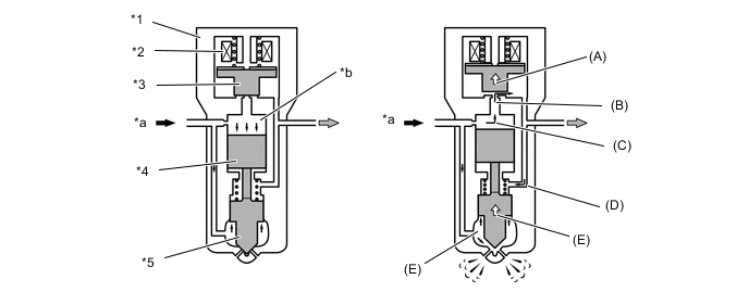
*1 Injector Assembly *2 Solenoid Coil *3 Solenoid Valve *4 Piston *5 Nozzle Needle - - *a Fuel *b Control Chamber
-
-
-
Models Compliant with EURO 5 Emission Regulations
-
General
-
8 piezo type injector assemblies are used. Each injector assembly consists of a nozzle needle, 2 pistons, a three-way valve and a piezo actuator.
-
An injector compensation value and QR (Quick Response) code containing encoded characteristics of the injector assembly are printed on each injector assembly.
-
The injector compensation value and QR code contain various pieces of information regarding the injector assembly, such as model code, injection volume correction and injection timing correction values.
*1 Injector Assembly *2 Piezo Actuator *3 No. 1 Piston *4 No. 2 Piston *5 Three-way Valve *6 Nozzle Needle
Tech Tips
-
If the ECM is replaced, use the Global TechStream (GTS) and input the injector compensation values of all 8 injector assemblies. If one of the injector assemblies is replaced, input the injector compensation value of the replaced injector assembly. Then, the proper compensation will be made so that the injection volume precision prior to the replacement will remain unchanged. For details, refer to the Repair Manual.
-
The QR code, which requires a special scan tool, is not used at LEXUS dealers.
*1 QR Code *2 Injector Compensation Value -
What is Quick Response (QR) Code?:
-
QR code, a matrix symbology consisting of an array of nominally square cells, allows omni-directional, high-speed reading of large amounts of data.
-
QR code encodes many types of date such as numeric, alphanumeric, kanji, kana and binary code. A maximum of 7,089 characters (numeric) can be encoded.
-
QR code (2D code) contains information in the vertical and horizontal direction, whereas a bar code contains data in one direction only. QR code (2D code) holds a considerably greater volume of information than a bar code.
-
-
Operation
-
(A): When current is applied to the piezo actuator, the No. 1 piston, No. 2 piston and three-way valve are pushed down.
-
(B): The orifice on the upper part of the three-way valve opens and the fuel in the control chamber flows out.
-
(C): The fuel pressure in the control chamber drops.
-
(D): As a result, the nozzle needle is pushed up due to fuel pressure, causing fuel injection.
-
(E): Current to the piezo actuator is shut off and the No. 1 and No. 2 pistons and the three-way valve are pushed up due to spring tension.
-
(F): The orifice on the upper part of the three-way valve closes to stop fuel flow.
-
(G): The fuel pressure in the control chamber rises.
-
(H): As a result, the nozzle needle goes down to stop fuel injection.
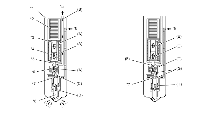
*1 Injector Assembly *2 Piezo Actuator *3 No. 1 Piston *4 No. 2 Piston *5 Orifice *6 Three-way Valve *7 Control Chamber *8 Nozzle Needle *a Return Fuel *b Fuel from Common-rail assembly
-
-
-
-
Fuel Tank
-
General
-
The multi-layer plastic fuel tank sub-assembly consists of 6 layers of 4 types of materials, and one of those is a recyclable material to address environmental concerns.
-
A jet pump, which automatically transfers fuel from the fuel sub tank sub-assembly to the fuel tank sub-assembly, and a fuel pump, which drives the jet pump, are provided in the fuel tank sub-assembly.*
-
*: Models with dual fuel tank
Figure 7. Cross Section of Fuel Tank Sub-assembly
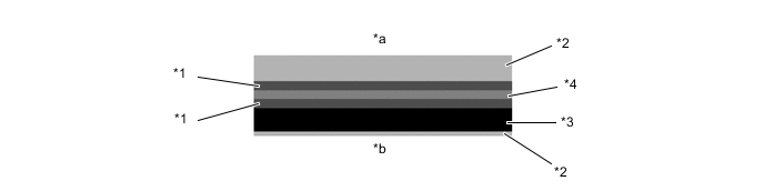
*1 Adhesive *2 High Density Polyethylene *3 Recyclable Material *4 Ethylene Vinyl Alcohol Copolymer *a Interior of Fuel Tank Sub-assembly *b Exterior of Fuel Tank Sub-assembly Tech Tips
Drain marks have been provided at the lowest position of the fuel tank sub-assembly. When dismantling (scraping) the vehicle, drain fuel by drilling holes at the drain mark.
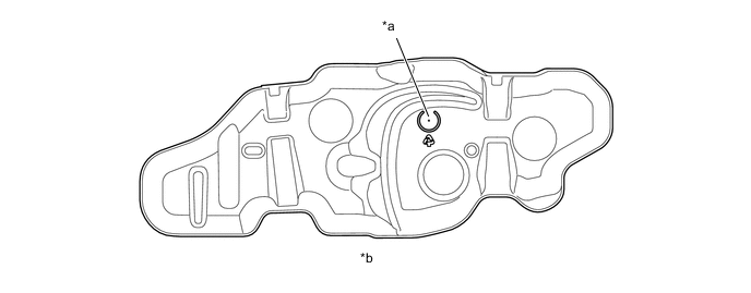
*a Drain Mark *b View from Bottom Side -
-
-
Construction of Dual Fuel Tank
-
General
-
A jet pump and fuel pump are provided in the fuel tank sub-assembly in order to automatically transfer fuel from the fuel sub tank sub-assembly to the fuel tank sub-assembly.
-
Fuel pump operation is controlled by the ECM in accordance with the actual fuel amount in the fuel tanks.
-
For the fuel filler pipe, the structure that is united right under the fuel inlet and forked into two in the middle is used in its configuration. Therefore, the driver can refuel without the need to distinguish the fuel tank sub-assembly from the fuel sub tank sub-assembly.
Figure 8. System Diagram
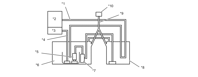
*1 Return Tube *2 Engine *3 Injection or Supply Pump Assembly *4 Main Tube *5 Fuel Pump *6 Fuel Tank Sub-assembly *7 Jet Pump *8 Fuel Sub Tank Sub-assembly *9 Fuel Filler Pipe *10 Fuel Inlet
-
-
Fuel Inlet
-
There is only 1 fuel filler pipe directly below the fuel inlet, which branches into 2 pipes at a midway point.

*1 Fuel Supply Nozzle *2 Fuel Inlet *3 Fuel Filler Pipe - - *a To Sub Fuel Tank Sub-assembly *b To Fuel Tank Sub-assembly
-
-
Operation
-
The fuel from the fuel pump actuates the jet pump in the fuel tank sub-assembly, in order to draw fuel from the fuel sub tank sub-assembly to the fuel tank sub-assembly.
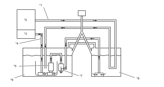
*1 Return Tube *2 Engine *3 Injection or Supply Pump Assembly *4 Main Tube *5 Fuel Pump *6 Fuel Tank Sub-assembly *7 Jet Pump *8 Fuel Sub Tank Sub-assembly -
The fuel from the fuel pump passes through the orifice in the jet pump and returns to the fuel tank sub-assembly. Because the flow speed of the fuel from the fuel pump increases as it passes through the orifice, a vacuum is created near the exit of the orifice. This vacuum causes the fuel to be drawn from the fuel sub tank sub-assembly to the fuel tank sub-assembly.
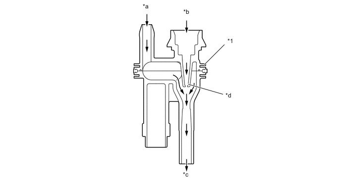
*1 Jet Pump - - *a From Fuel Sub Tank Sub-assembly *b From Fuel Pump *c To Fuel Tank Sub-assembly *d Orifice
-
-
-
-
Fuel Filter
-
General
-
While the fuel filter element of the conventional fuel filter has been integrated with the fuel filter case, the new fuel filter consists of a separate fuel filter element and fuel filter case. A paper filter element that offers high filtering efficiency and captures the minutest particles is used.
-
A fuel filter warning switch, which turns ON/OFF when the internal vacuum of the filter increases, is provided in the fuel filter.
-
A recirculation type fuel heater is provided, in order to improve the fuel heating performance.*
-
*: Models with fuel heater
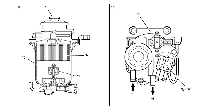
*A Models with Fuel Heater - - *1 Priming Pump *2 Fuel Filter Case *3 Fuel Sedimenter Level Warning Switch *4 Fuel Filter Element *5 Fuel Filter Warning Switch *6 Fuel Heater *a Cross Section *b Top View *c From Fuel Tank Sub-assembly *d To Injection or Supply Pump Assembly Figure 9. System Diagram
-
-
-
Fuel Filter Warning Switch
-
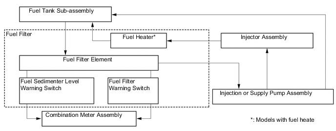
A fuel filter warning switch, which turns ON/OFF when the internal vacuum of the filter increases, is provided in the fuel filter. This switch, which turns OFF when the internal vacuum of the fuel filter increases to a predetermined level, is connected by wire to the meter ECU.
-
When the meter ECU detects that the internal vacuum of the fuel filter has increased (by way of the fuel filter warning switch OFF signal), it determines that the fuel filter has become clogged. Then it displays the fuel system warning message on the multi-information display on the combination meter assembly to urge the driver to replace the fuel filter.
-
-
Fuel Sedimenter Level Warning Switch
-
When the water in the sedimenter section reaches a certain amount, the level warning switch comes ON and the fuel system warning message in the multi-information display displayed.
-
-
Fuel Heater (Models with Fuel Heater)
-
This heater heats the fuel by recirculating the returned fuel, which becomes to have a high temperature by the fuel pumping of the injection or supply pump assembly, to the fuel filter.
-
The fuel heater uses a recirculation valve (bimetal), which is mounted on the fuel return line and opens and closes in accordance with the fuel temperatures to draw return fuel to the fuel filter.
-
While the engine is cold, the recirculation valve inside the fuel heater will open due to the bimetal action, so the return fuel will return to the fuel filter and the fuel tank sub-assembly.
-
While the engine is warm, the recirculation valve will close due to the bimetal action, so all the return fuel will return to the fuel tank sub-assembly.
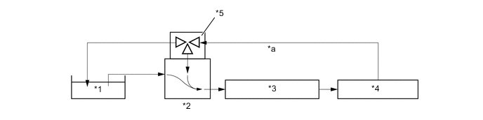
*1 Fuel Tank Sub-assembly *2 Fuel Filter *3 Injection or Supply Pump Assembly *4 Injector Assembly *5 Recirculation Type Fuel heater - - *a Return - -
-
-
-
Fuel Cooler
-
The two types of the fuel cooler assemblies are used; one is the water-cooled type, and the other is the air-cooled type. These fuel cooler assemblies, which are provided in the fuel return path, cool the return fuel that has reached a high temperature as a result of the pumping of the injection or supply pump assembly. This prevents the reduction in fuel viscosity that is caused by the rise in fuel temperature, and improves the reliability of the fuel system.*
-
*: Except models compliant with EURO 5 emission regulations
Figure 10. Water-cooled Type Fuel Cooler
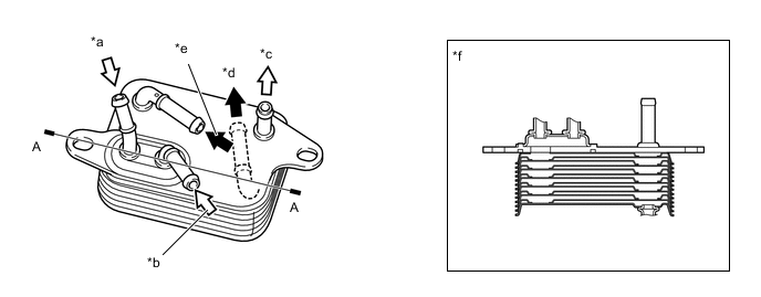
*1 Fuel Cooler Assembly - - *a Fuel (From Left Bank) *b Fuel (From Right Bank) *c Fuel (To Fuel Tank Sub-assembly) *d Water Out *e Water IN *f A - A Cross Section Figure 11. Air-cooled Type Fuel Cooler
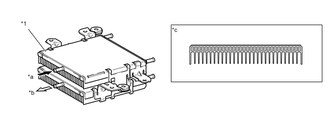
*1 Fuel Cooler Assembly - - *a From Common-rail Assembly *b To Fuel Tank Sub-assembly *c Fuel Cooler Cross Section - - -
-
-
Exhaust Fuel Addition Injector
-
An exhaust fuel addition injector assembly is installed on each cylinder head sub-assembly. This injector supplies additional fuel into the exhaust port and maintains the proper catalyst temperature for the purpose of PM recovery.
-
An exhaust fuel addition injector assembly consists of a needle valve body, a needle valve, and a solenoid valve.

*1 Solenoid Valve *2 Needle Valve *3 Needle Valve Body - -
-