AB60F AUTOMATIC TRANSMISSION
-
GENERAL
-
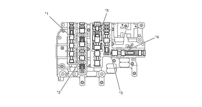
The valve body consists of the upper (No. 1 and No. 2) and lower (No. 1 and No. 2) valve bodies and 9 shift solenoid valves.
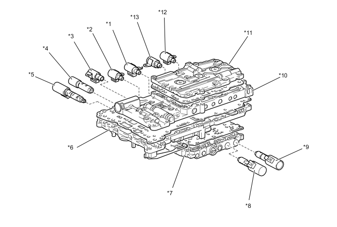
*1 Shift Solenoid Valve S4 *2 Shift Solenoid Valve S1 *3 Shift Solenoid Valve SR *4 Shift Solenoid Valve SL1 *5 Shift Solenoid Valve SLT *6 Lower Valve Body *7 No. 2 Lower Valve Body *8 Shift Solenoid Valve SL2 *9 Shift Solenoid Valve SLU *10 No. 1 Upper Valve Body *11 No. 2 Upper Valve Body *12 Shift Solenoid Valve S3 *13 Shift Solenoid Valve S2 - - Figure 1. No. 1 Upper Valve Body
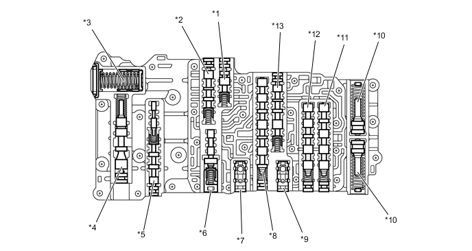
*1 Clutch Control Valve *2 Clutch Apply Relay Valve *3 C1 Accumulator *4 Secondary Regulator Valve *5 Lock-up Relay Valve *6 Lock-up Control Valve *7 C3 Check Valve *8 1 - 2 Shift Valve *9 B4 Outer Check Valve *10 B2 Accumulator *11 3 - 4 Shift Valve *12 2 - 3 Shift Valve *13 Reverse Sequence Valve - - Figure 2. No. 2 Upper Valve Body
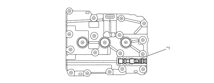
*1 C3 Apply Relay Valve - - Figure 3. Lower Valve Body
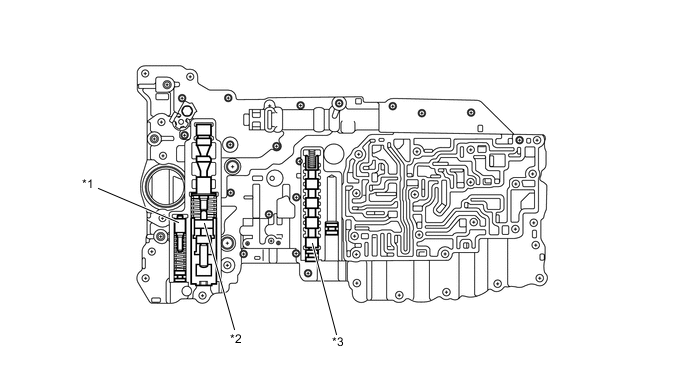
*1 SLT Damper *2 Primary Regulator Valve *3 4 - 5 Shift Valve - - Figure 4. No. 2 Lower Valve Body
*1 B1 Apply Relay Valve *2 SL1 Relay Valve *3 Brake Control Valve *4 Solenoid Modulator Valve *5 Accumulator Control Valve - -
-
-
SHIFT SOLENOID VALVE
-
Shift Solenoid Valves S1, S2, S3, S4 and SR
-
These solenoid valves are 3-way solenoid valves.
-
A filter is provided at the tip of the solenoid valve to further improve operational reliability.
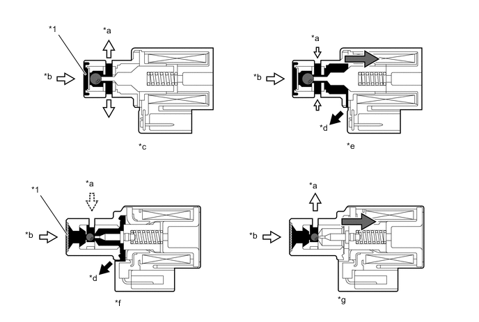
*1 Filter - - *a Control Pressure *b Line Pressure *c Shift Solenoid Valve S1 Off *d Drain *e Shift Solenoid Valve S1 On *f Shift Solenoid Valve S4 Off *g Shift Solenoid Valve S4 On - - Function of Shift Solenoid Valves S1, S2, S3, S4 and SR Shift Solenoid Valve Function S1
-
Switches the 1 - 2 shift valve.
-
Switches the SL1 relay valve.
S2
-
Switches the 2 - 3 and 5 - 6 shift valves.
-
Switches the 1 - 2 shift valve.
S3 Switches the 3 - 4 shift valve. S4
-
Switches the 4 - 5 shift valve.
-
Switches the SL1 relay valve.
-
Switches the reverse sequence valve.
SR
-
Switches the clutch apply relay valve.
-
Switches the B1 relay valve.
-
-
-
Shift Solenoid Valves SL1, SL2, SLT and SLU
-
SL1, SL2, SLT, and SLU are used by the ECM to control hydraulic pressures in a linear fashion based on the current that the ECM causes to flow through their solenoid coils. They control line, clutch, and brake engagement pressures based on the signals received from the ECM.
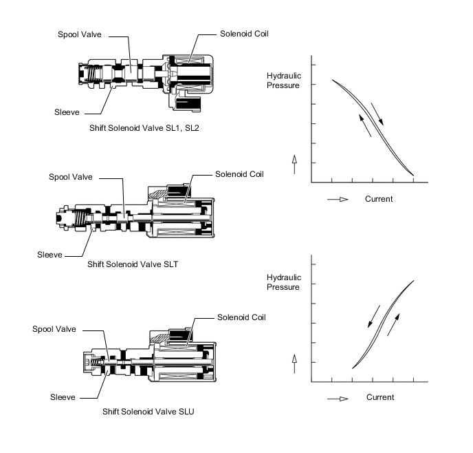
Function of Shift Solenoid Valves SL1, S2, SLT and SLU Shift Solenoid Valve Function SL1
-
Clutch pressure control
-
Accumulator back pressure control
SL2 Brake pressure control SLT
-
Line pressure control
-
Accumulator back pressure control
SLU Lock-up clutch pressure control -
-
-