PRE-CRASH SAFETY SYSTEM
Info Added 2017-07-26 ![]()
-
FUNCTION OF MAIN COMPONENTS
Item Function Combination Meter Assembly PCS Warning Light
(PCS OFF Indicator Light)
-
Flashes or illuminates to warn the driver in accordance with signals from the driving support ECU assembly.
-
Flashes or illuminates when the system is malfunctioning or temporarily disabled.
-
Illuminates when the pre-crash safety system is disable.
-
Illuminates when the pre-crash safety system is not available due to certain reasons or when pre-crash brake and pre-crash brake assist operation are disabled using the VSC OFF switch.
Multi-information Display
-
Displays a warning message to inform or warn the driver of the system condition in accordance with signals from the driving support ECU assembly.
-
Disables the pre-crash safety system operation when selected PCS OFF mode in setting display function.
-
Changing the pre-crash safety system warning timing when selected Far/Middle/Near in setting display function.
Master Warning Light Illuminates to warn the driver in accordance with signals from the driving support ECU assembly. Buzzer Sounds to warn the driver in accordance with signals from the driving support ECU assembly when the system is malfunctioning. Millimeter Wave Radar Sensor Assembly Radiates millimeter wave radar forward, uses the reflected millimeter waves for detecting the presence of a vehicle ahead, the vehicle-to-vehicle distance, and the relative speed, and then transmits this information to the driving support ECU assembly. Forward Recognition Camera
-
Captures images of the area in front of the vehicle and processes them to detect vehicles and sends information to the driving support ECU assembly.
-
Operates the camera heater when temperature is cold.*
Driving Support ECU Assembly Determines whether a collision is imminent based on the information received from the sensors. It then outputs a brake assist standby request signal and pre-crash braking request signal if required. Forward Recognition Bracket Assembly Camera Heater* Heats the sheet heater in accordance with the current from the forward recognition camera to prevent condensation on windshield in front of the forward recognition camera (camera sensor). Brake Actuator Assembly Master Cylinder Pressure Sensor Detects the master cylinder pressure and transmits a signal to the skid control ECU. Skid Control ECU
-
Receives a brake assist standby request signal from the driving support ECU assembly and switches the brake assist to standby mode. When a master cylinder pressure signal is input, it activates the brake assist.
-
Receives a pre-crash brake request signal from the driving support ECU assembly, and then applies the brakes.
-
Transmits vehicle speed signals to the driving support ECU assembly.
Speed Sensor Detect the wheel speed of each of the 4 wheels and transmits the signals to the skid control ECU. Airbag Sensor Assembly Yawrate Sensor Detects the yaw rate and lateral/longitudinal deceleration of the vehicle and transmits the signal to the skid control ECU and the driving support ECU assembly. Steering Sensor Detects the angle and direction of steering and transmits a signal to the skid control ECU and the driving support ECU assembly. Steering Pad Switch Assembly Meter Control Switches The multi-information display is operated using the meter control switches VSC OFF Switch Disables the pre-crash brake and pre-crash brake assist operation when VSC OFF mode. Skid Control Buzzer Assembly Sounds to warn the driver in accordance with signals from the driving support ECU. Stop Light Switch Assembly Detects if the brake pedal is depressed and transmits a signal to the skid control ECU and driving support ECU. Engine Room Relay Block and Junction Block Assembly Integration Relay
- Stop Light Control Relay
Receives a stop light turn on request signal from the skid control ECU, and turns on the stop lights. Main Body ECU (Multiplex Network Body ECU) Outputs the specification signal of the vehicle to driving support ECU. Central Gateway ECU Transmits the signal between the CAN communication bus. *: Models with camera heater
-
-
FUNCTION
-
The pre-crash safety system uses a millimeter wave radar sensor and forward recognition camera to detect vehicle in front of your vehicle.
-
When the system determines that the possibility of a frontal collision with a vehicle is high, a warning operates to urge the driver to take evasive action and the potential brake pressure is increased to help the driver avoid the collision.
-
If the system determines that the possibility of a frontal collision with a vehicle is imminent, the brakes are automatically applied to help avoid the collision or help reduce the impact to the vehicle occupants and the vehicle in the collision.
-
pre-crash safety system warning
When the system determines that the possibility of a frontal collision is high, a buzzer will sound and a warning message will be displayed on the multi-information display to urge the driver to take evasive action.
-
pre-crash brake assist
When the system determines that the possibility of a frontal collision is high, the system applies greater braking force in relation to how strongly the brake pedal is depressed.
-
pre-crash braking
If the system determines that the possibility of a collision is extremely high, the brakes are automatically applied to help avoid the collision or reduce the impact.
-
-
Warning Indication
-
The combination meter assembly uses the multi-information display, master warning light, PCS warning light and buzzer to provide the driver with pre-crash safety system malfunction and indications.
-
If the driving support ECU assembly determines that the possibility of a collision is high it sends a signal to the combination meter assembly. Upon receiving this signal, the combination meter assembly indicates a warning using the multi-information display and skid control buzzer assembly. Details are indicated below.
When there is a high possibility of a collision Multi-information Display Skid Control Buzzer Assembly BRAKE ! Sounds Continuously -
When the system is not available, the following warning occurs to warn the driver.
When a system malfunction and unavailable are detected Multi-information Display Detail Master Warning Light PCS Warning Light Buzzer DTC Pre-Crash Safety System Malfunction
Visit Your Dealer
This message appears when the driving support ECU assembly detects a system malfunction. Illuminates Flashes Sounds once Repair is required
DTCs are stored
Pre-crash safety System Unavailable Millimeter wave radar sensor assembly is misaligned - Flashes - - Pre-Crash Safety System Unavailable
Clean Sensor
Dirty center mark of upper radiator grille or millimeter wave radar sensor assembly - Flashes - - Front Camera Systems Unavailable
Clean Windshield
Debris on area of windshield glass in front of forward recognition camera - Illuminate - - Front Camera Systems Unavailable Temperature or power supply of Pre-crash safety system city sensor is abnormality - Flashes - - VSC Turned Off
Pre-Crash Safety System Unavailable
VSC and TRC operation has not been disabled - Illuminate - -
-
-
Changing settings of the pre-crash safety system
-
To change the enabled or disabled of the pre-crash safety system using the multi-information display and the steering pad switch assembly (meter control switches), display the setting display screen.
-
On the setting display screen, select PCS icon and then press on Enter/Set switch on the steering wheel pad switch assembly.
-
Select [PCS] and then press on Enter/Set switch the steering wheel. Each time is pressed, the system will be enabled/disabled.
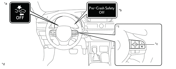
*a PCS warning Light *b Multi-information Display *c Steering Pad Switch Assembly
- Meter Control Switches
*d Enter/Set Switch Tech Tips
-
If the system is disabled, the PCS warning light will turn on and a message will be displayed on the multi-information display.
-
The system is automatically enabled each time the engine switch is turned to ON mode.
-
-
-
The pre-crash safety system warning timing can be changed on setting display of the multi-information display.
-
On the setting display screen, select PCS icon and then press on Enter/Set switch on the steering wheel pad switch assembly.
-
Select [Sensitivity] and then press on Enter/Set switch the steering wheel. Each time Enter/Set switch is pressed, operation timing (Far/Middle/Near) of the pre-crash safety system will be changed.
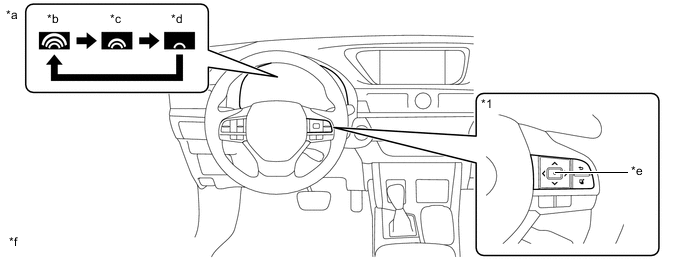
*a Multi-information Display *b Far *c Middle *d Near *e Steering Pad Switch Assembly
- Meter Control Switches
*f Enter/Set Switch
-
-
-
-
OPERATING CONDITION
-
For vehicles sold in regions where the pre-crash braking functions are available
Tech Tips
Depending on the region in which the vehicle was sold, the pre-crash braking function may not be available.
-
The pre-crash safety system is enabled and the system determines that the possibility of a frontal collision with a vehicle is high.
-
Vehicle speed is between approximately 15 and 180 km/h (10 and 110 mph).
Pre-crash safety system warning:
-
Vehicle speed is between approximately 30 and 180 km/h (19 and 110 mph).
Pre-crash brake assist:
-
Vehicle speed is between approximately 15 and 180 km/h (10 and 110mph).
Pre-crash braking:
-
If a battery terminal has been disconnected and reconnected and then the vehicle has not been driven for a certain amount of time
-
If VSC is disabled (only the pre-crash safety system warning function will be operational)
-
If the PCS warning light is flashing or illuminated
The system may not operate in the following situations:
-
-
-
For vehicles sold in regions where the pre-crash brake is not available and the pre-crash brake assist function is available
-
The pre-crash safety system is enabled and the system determines that the possibility of a frontal collision with a vehicle is high.
-
Vehicle speed is between approximately 15 and 180 km/h (10 and 110 mph).
-
The relative speed between your vehicle and the vehicle ahead is approximately 10km/h (7 mph) or more.
Pre-crash safety system warning:
-
Vehicle speed is between approximately 30 and 180 km/h (19 and 110 mph).
-
The relative speed between your vehicle and the vehicle ahead is approximately 30km/h (19 mph) or more.
Pre-crash brake assist:
-
If a battery terminal has been disconnected and reconnected and then the vehicle has not been driven for a certain amount of time
-
If VSC is disabled (only the pre-crash safety system warning function will be operational)
-
If the PCS warning light is flashing or illuminated
The system may not operate in the following situations:
-
-
-
Cancelation of the pre-crash braking
Tech Tips
Depending on the region in which the vehicle was sold, the pre-crash braking function may not be available.
-
If either of the following occur while the pre-crash braking function is operating, it will be canceled:
-
The accelerator pedal is depressed strongly.
-
The steering wheel is turned sharply or abruptly.
-
-
If the vehicle is stopped by the operation of the pre-crash braking function, the operation of the pre-crash braking function will be canceled after the vehicle has been stopped for approximately 2 seconds.
-
-
Conditions under which the system may operate even if there is not a high possibility of a collision
-
In the following situations the system may determine that there is a high possibility of a frontal collision and operate.
-
When driving on roads with sharp changes in elevation

-
When the vehicle is hit by water, snow, dust, etc. from a preceding vehicle or oncoming vehicle
-
When driving through fog, steam or smoke
-
When passing a vehicle in an oncoming lane that is stopped to make a right/left turn

-
When there is a metal object, steps, protrusion, etc. on a road surface or roadside
-
When there is a metal object (manhole cover, steel plate, etc.) on the road at the beginning or bottom of a hill

-
When there is a structural object (billboard, street light, etc.) at the top of an uphill road

-
When approaching an overpass, traffic sign, billboard, etc.

-
When rapidly closing on an electric toll gate barrier, parking area barrier, or other barrier that opens and closes
-
When driving in a tunnel with a low ceiling or when parking near a low hanging object

-
When the road surface is rough or uneven, such as an undulating or unpaved road
-
When driving through or under objects that may contact the vehicle, such as thick grass, tree branches, or a banner

-
When driving in a narrow tunnel, or on an iron bridge or a narrow path surrounded by objects on the roadside (guardrail, poles, etc.)
-
When the road surface is rough or uneven, such as an undulating or unpaved road
-
When driving through or under objects that may contact the vehicle, such as thick grass, tree branches, or a banner
-
When driving in a narrow tunnel, or on an iron bridge or a narrow path surrounded by objects on the roadside (guardrail, poles, etc.)
-
When there are patterns or paint on the road or a wall that may be mistaken for a vehicle
-
When driving near a reflective object, such as a large truck or guardrail
-
When driving near a TV tower, broadcasting station, electric power plant, or other location where strong radio waves or electrical noise may be present
-
When a preceding vehicle suddenly decelerates
-
When driving on a road where relative location to preceding vehicles in an adjacent lane may change, such as on a winding road

-
-
In the following situations, the system may determine that there is a high possibility of a frontal collision and operate:
-
When overtaking a preceding vehicle that is making a left/right turn

-
When changing lanes while overtaking a preceding vehicle
-
When overtaking a preceding vehicle that is changing lanes
-
When driving between vehicles

-
When driving between parked vehicles

-
-
-
-
SYSTEM CONTROL
-
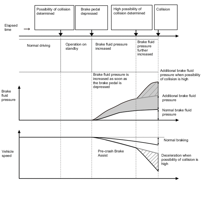
Pre-crash Brake Assist
-
When the driver depresses the brake pedal after the pre-crash safety system has determined that there is the possibility of a collision, brake fluid pressure is increased. If the possibility of a collision is still high, brake fluid pressure is further increased.
-
-
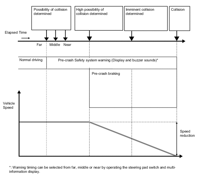
Pre-crash Brake
Tech Tips
Depending on the region in which the vehicle was sold, the pre-crash braking function may not be available.
-
When the pre-crash safety system detects an object in front of the vehicle and determines that the possibility of a collision is high, the PCS warning light in the combination meter assembly blinks and a warning buzzer sounds to warn the driver.
-
When the pre-crash safety system determines that a collision is imminent, the system performs pre-crash brake control.
-
-
-
CONSTRUCTION
-
Millimeter Wave Radar Sensor Assembly
-
The millimeter wave radar sensor assembly consists of a millimeter wave radar circuit, signal processing circuit and CPU.
-
The millimeter wave radar outputs waves when the vehicle speed is above 0 km/h (0 mph), and not when the vehicle speed is at 0 km/h (0 mph). The millimeter wave radar uses frequencies in the 76 GHz band.
-
The reception antennas receive the millimeter wave radar waves that have been reflected.
-
The signal processing circuit detects the distance, relative speed, and the direction of the object by generating millimeter wave radar waves and calculating the signals received by the reception antennas. Then, it transmits this information to the driving support ECU assembly.
-
-
Forward Recognition Camera
-
Forward Recognition Camera is equipped with an internal monocular camera.
-
2 types of sensors such as the millimeter wave radar sensor and a forward recognition camera are used to ensure accurate and reliable detection.
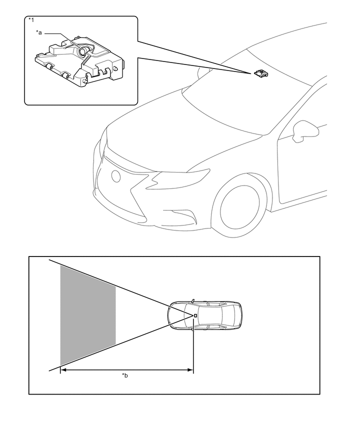
Text in Illustration *1 Forward Recognition Camera - - *a Monocular Camera *b Detection Area
-
-
Camera Heater
-
The camera heater is positioned in the forward recognition bracket assembly. The camera heater prevents condensation on the windshield in front of the forward recognition camera (camera sensor).
-
The camera heater operates with the current from the forward recognition camera (camera sensor).
-
The camera heater is composed of the sheet heater (heating element) and temperature fuse, etc. Current is run through the sheet heater (heating element) to generate heat and warm the front portion of the forward recognition camera (camera sensor).
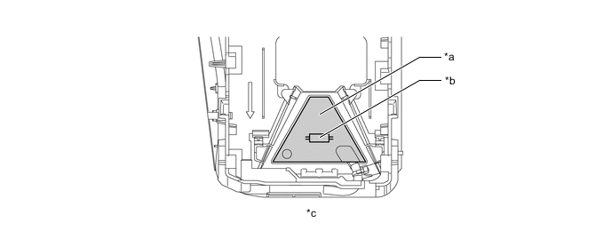
*a Sheet Heater (Heating Element) *b Temperature Fuse (Built-in parts) *c Forward Recognition Bracket Assembly Behind View - - Heater Specifications Item Specification Heat Generation 5 W or less -
Operating Condition
-
When all of the following conditions have been met, the camera heater operates.
-
The power switch is turned on (IG).
-
The outside air temperature is approximately 10°C (50°F) or less.
-
A few minutes have elapsed since the camera heater operation stopped.
-
After the camera heater operates, the operation will stop when a certain length of time has elapsed.
Tech Tips
Operating time will differ depending on vehicle conditions (vehicle speed, outside air temperature, etc.).
-
-
-
-
DIAGNOSIS
-
Initial Check
-
The driving support ECU performs an initial check on the system for approximately 3 seconds after the power switch has been turned on (IG).
-
-
Monitor Function
-
After completing the initial check, the pre-crash safety system becomes ready to operate. During this time, the driving support ECU periodically monitors the system for any malfunctions.
-
-
Diagnostic Trouble Code (DTC)
-
If the driving support ECU assembly detects a malfunction in the pre-crash safety system.
-
-