БЛОК ДВИГАТЕЛЯ ДЕТАЛЬНОЕ ОПИСАНИЕ
-
CONSTRUCTION
-
Cylinder Head Cover Sub-assembly
-
A lightweight yet high-strength aluminum cylinder head cover sub-assembly is used.
-
Acrylic rubber, which excels in heat resistance and reliability, is used for the cylinder head cover gasket.
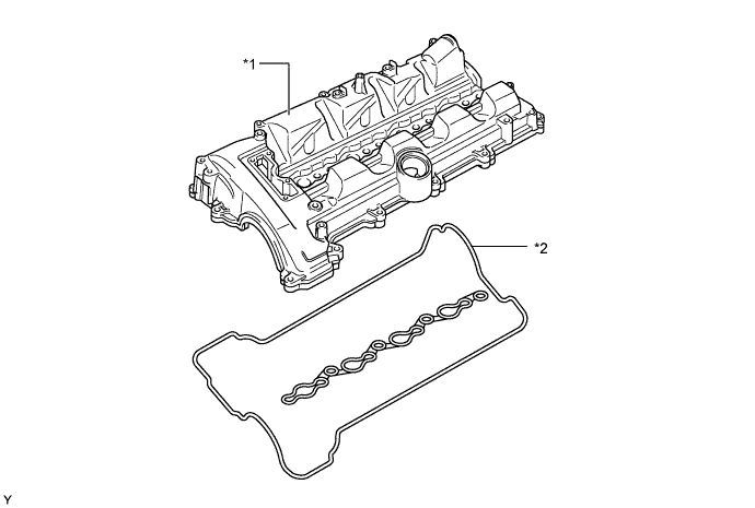
Text in Illustration *1 Cylinder Head Cover Sub-assembly *2 Cylinder Head Cover Gasket
-
-
Cylinder Head Sub-assembly
-
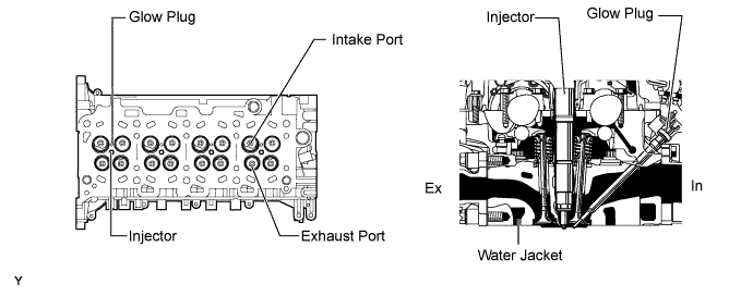
The cylinder head sub-assembly is made of aluminum alloy.
-
The injector is located in the center of the combustion chamber in order to improve engine performance and achieve cleaner emission.
-
A glow plug is placed between the intake ports of each cylinder to ensure startability.
-
A passage for the Exhaust Gas Recirculation (EGR) is provided in the cylinder head sub-assembly. By cooling the exhaust gas, a large amount of exhaust gas is able to recirculate.
-
A water jacket is provided for the intake and exhaust ports respectively to achieve excellent cooling performance.
-
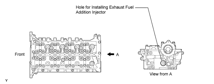
On models with the DPF catalyst, a hole for installing the exhaust fuel addition injector is located on the No. 4 exhaust port of the cylinder head sub-assembly.
-
-
Cylinder Block Sub-assembly
-
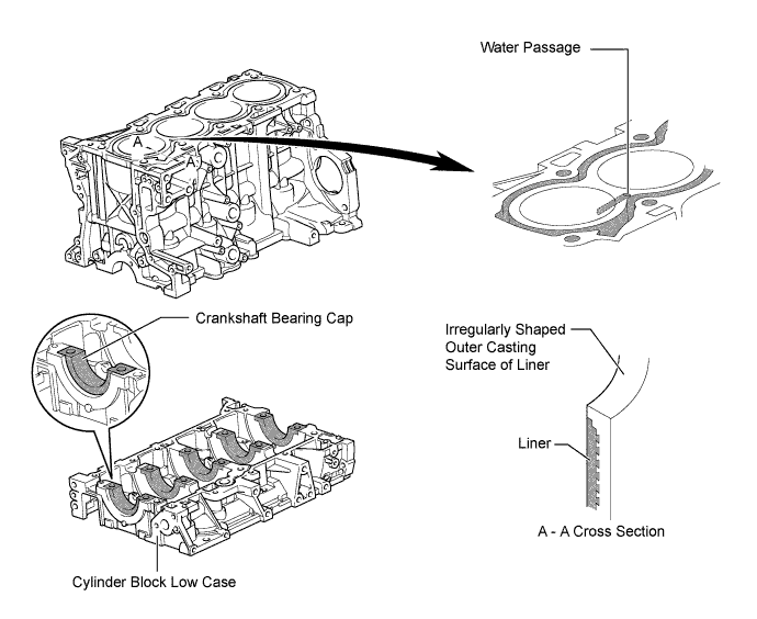
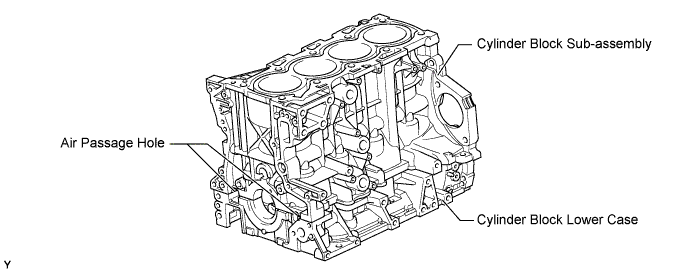
The cylinder block sub-assembly is made of aluminum alloy.
-
A water passage is provided between the cylinder bores. By allowing the water to flow between the cylinder bores, this construction enables the temperature of the cylinder walls to be kept uniform.
-
The liners are the spiny-type, which are manufactured so that their casting exterior forms a large irregular surface in order to enhance the adhesion between the liners and the aluminum cylinder block sub-assembly. The enhanced adhesion helps improve heat dissipation, resulting in a lower overall temperature and reduced heat deformation of the cylinder bores.
-
Crankshaft bearing caps with cylinder block lower cases are used to reduce noise and to increase the coupling rigidity with the crankshaft.
-
Cast-iron is used as a material for part of the bearing journal of the crankshaft bearing cap, thus helping prevent deformation caused by high loads from the crankshaft.
-
Plastic region tightening bolts are used for tightening the crankshaft bearing cap.
Tech Tips
Because liner is thin, reboring is not possible.
-
Air passage holes are provided on bulkheads of the cylinder block sub-assembly and cylinder block lower case. As a result, the air at the bottom of the cylinder flows smoother, and pumping loss (back pressure at the bottom of the piston generated by the piston's reciprocating movement) has been reduced to improve the engine's output.
-
-
Piston
-
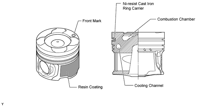
The pistons are made of aluminum alloy.
-
Combustion chambers are provided on the pistons for direct injection.
-
The shape of the combustion chamber has been optimized to achieve a low compression ratio, high engine output, and low fuel consumption.
-
A cooling channel is provided to achieve excellent piston cooling performance.
-
To improve the wear resistance of the top ring groove, a Ni-resist cast iron ring carrier is used.
-
Along with the improved engine performance, the piston skirt is applied with a resin coating to reduce friction loss.
-
Due to increased machining precision of the cylinder bore diameter, it is not necessary to prepare pistons with different diameters.
-
-
Connecting Rod Sub-assembly and Connecting Rod Bearing
-
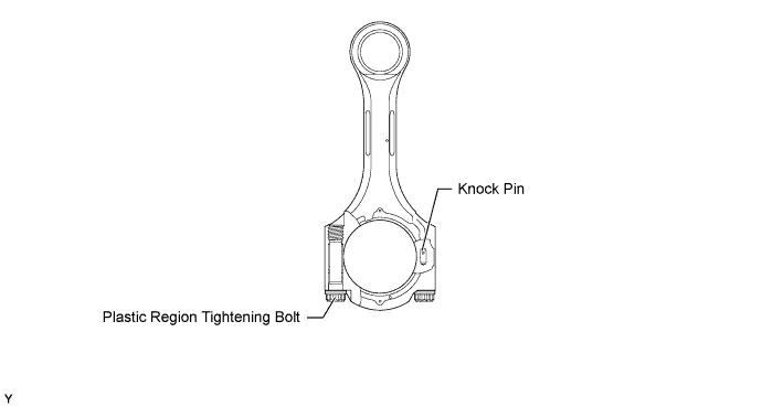
The connecting rod sub-assemblies and caps are made of high-strength steel for weight reduction.
-
Knock pins are used at the mating surfaces of the bearing caps of the connecting rod to minimize the shifting of the bearing caps during assembly.
-
Plastic region tightening bolts are used on the connecting rods.
-
The connecting rod bearings are reduced in width to reduce friction.
-
-
Crankshaft
-
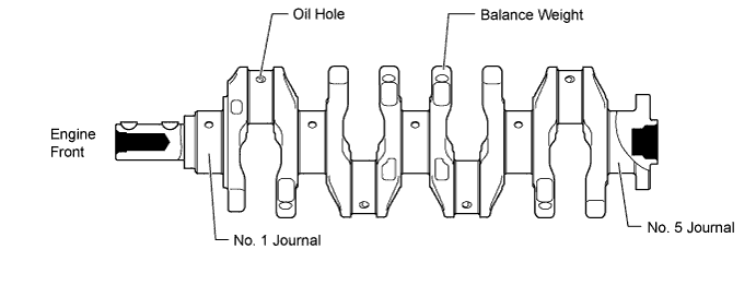
A crankshaft made of forged steel, which excels in rigidity and wear resistance, is used.
-
The crankshaft has 5 journals, 4 crank pins and 8 balance weights.
-
-
Crankshaft Pulley
-
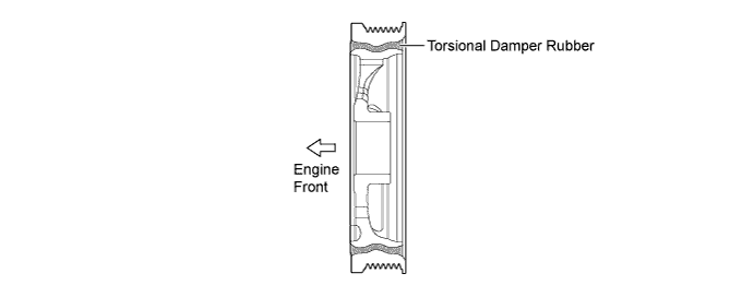
The rigidity of the crankshaft pulley with its built-in torsional damper rubber reduces noise.
-
The Ethylene Propylene Diene Monomer (EPDM) material is used for the torsional damper rubber to achieve high durability and reliability.
-
-
Valve Mechanism
-
Each cylinder of this engine has 2 intake valves and 2 exhaust valves. Intake and exhaust efficiency is increased due to the larger total port areas.
-
This engine uses valve rocker arm sub-assembly with built-in needle bearings. This reduces the friction that occurs between the cams and the areas (valve rocker arm sub-assembly) that push the valves down, thus improving fuel economy.
-
A valve lash adjuster assembly, which maintains a constant 0 valve clearance through the use of oil pressure and spring force, is used.
-
The No. 2 camshaft is driven by a chain sub-assembly (timing chain), while the camshaft (intake camshaft) is driven through gear on the No. 2 camshaft (exhaust camshaft).
-
A supply pump is driven by No. 2 camshaft (exhaust camshaft) to achieve a lightweight and compact design.
-
A vacuum pump assembly is driven by camshaft to achieve a lightweight and compact design.
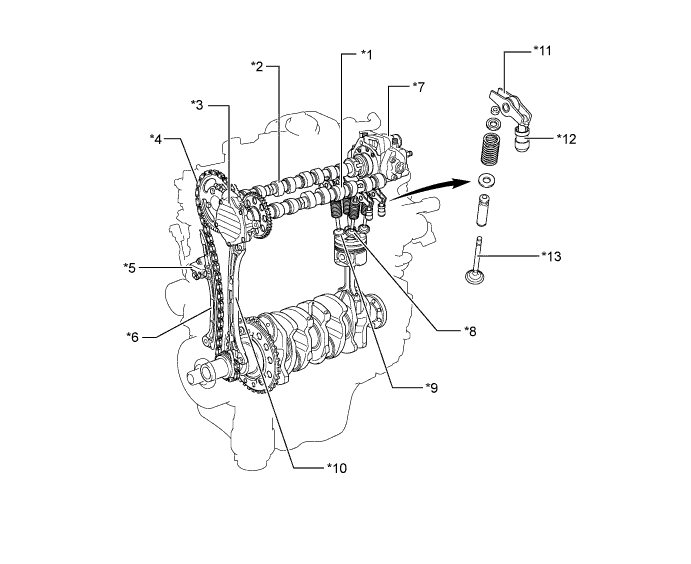
Text in Illustration *1 Camshaft (Intake Camshaft) *2 No. 2 Camshaft (Exhaust Camshaft) *3 Vacuum Pump Assembly *4 Chain Sub-assembly (Timing Chain) *5 No. 1 Chain Tensioner Assembly *6 Chain Tensioner Slipper *7 Supply Pump *8 Intake Valve *9 Exhaust Valve *10 No. 1 Chain Vibration Damper *11 Valve Rocker Arm Sub-assembly *12 Valve Lash Adjuster Assembly *13 Valve - - 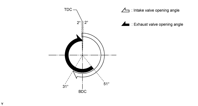
-
-
Chain Sub-assembly (Timing Chain) and No. 1 Chain Tensioner Assembly
-
A bushed chain with 9.525 mm (0.375 in.) pitch is used to make the engine more compact and to achieve a maintenance-free operation.
-
A chain oil jet lubricates the chain sub-assembly (timing chain).
-
The No. 1 chain tensioner assembly uses a spring and oil pressure to maintain proper chain tension at all times. A ratchet type assembly with backlash mechanism is used.
-
The chain tensioner suppresses noise generated by the chain.
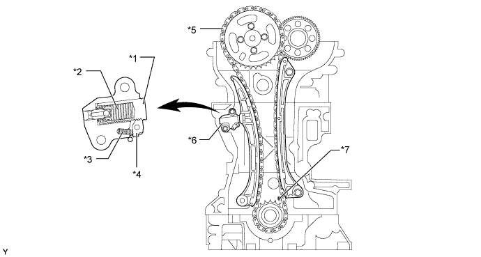
Text in Illustration *1 Plunger *2 Plunger Spring *3 Cam Spring *4 Cam *5 Chain Sub-assembly (Timing Chain) *6 No. 1 Chain Tensioner Assembly *7 Chain Oil Jet - -
-
-
Valve Lash Adjuster Assembly
-
The valve lash adjuster assembly, which is located at the fulcrum of the valve rocker arm sub-assembly, consists primarily of a plunger, a plunger spring, a check ball, and a check ball spring.
-
The engine oil supplied by the cylinder head sub-assembly and the built-in spring actuates the valve lash adjuster assembly. The oil pressure and the spring force that act on the plunger push the valve rocker arm sub-assembly against the cam, in order to adjust the valve clearance created during the opening and closing of the valve. As a result, engine noise has been reduced.
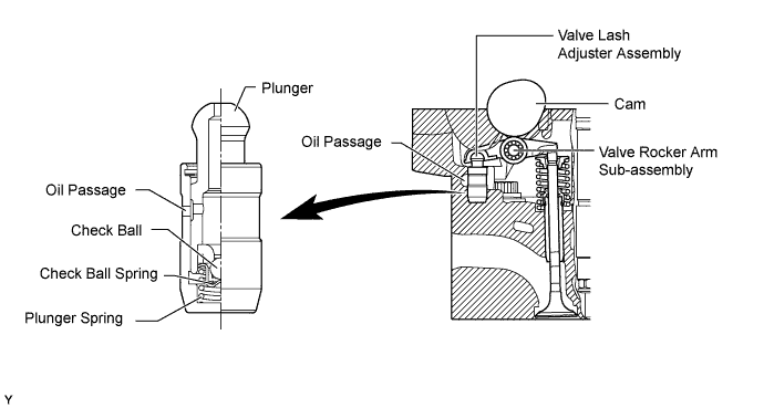
Tech Tips
Valve clearance adjustment is not necessary because a valve lash adjuster assembly is used. After reassembling the valve lash adjuster assembly, the fluid should be changed.
-
-
V-ribbed Belt
-
Accessory components are driven by a serpentine belt consisting of a single V-ribbed belt. This reduces the overall engine length, weight and the number of engine parts.
-
An automatic tensioner eliminates the need for tension adjustment.
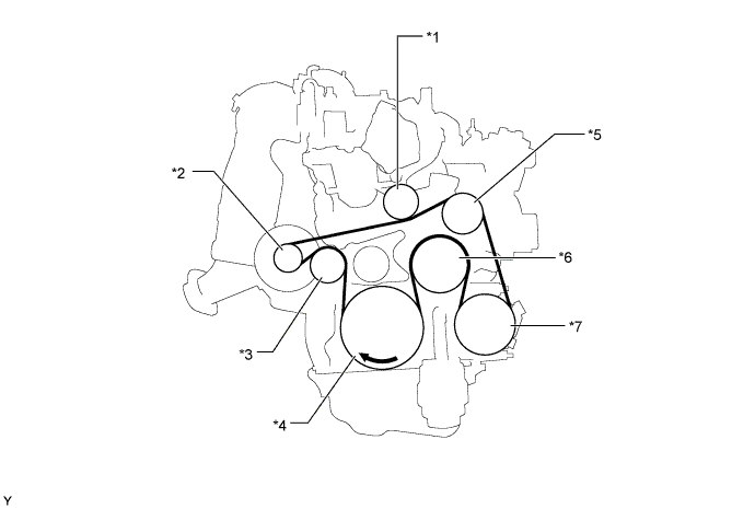
Text in Illustration *1 Belt Idler *2 Generator Pulley *3 Idler Pulley for Automatic Tensioner *4 Crankshaft Pulley *5 Idler Pulley *6 Water Pump Pulley *7 Air Conditioning Compressor Pulley*a - -
-
*a: Models with air conditioning
-
-
-