СИСТЕМА АВТОМАТИЧЕСКОЙ ТРАНСМИССИИ ДЕТАЛЬНОЕ ОПИСАНИЕ
-
FUNCTION OF MAIN COMPONENTS
Component Function No. 1 Clutch (C1)
Connects the intermediate shaft and the Ravigneaux planetary rear sun gear. No. 2 Clutch (C2)
Connects the intermediate shaft and the Ravigneaux planetary ring gear. No. 1 Brake (B1)
Prevents the Ravigneaux planetary front sun gear and the underdrive planetary carrier from turning clockwise or counterclockwise. No. 2 Brake (B2)
Prevents the Ravigneaux planetary ring gear from turning clockwise or counterclockwise. No. 3 Brake (B3)
Prevents the underdrive planetary ring gear from turning clockwise or counterclockwise. No. 1 1-way Clutch (F1)
Prevents the Ravigneaux planetary ring gear from turning counterclockwise. Planetary Gears These gears change the route through which driving force is transmitted, in accordance with the operation of each clutch and brake, in order to increase or reduce the input and output speed. Torque Converter Clutch Assembly
-
Transmits the engine power to the transaxle.
-
Increases engine torque.
Oil Pump Assembly Provides oil pressure necessary for the transaxle operation. Shift Solenoid Valve SL1 Controls the No. 1 clutch (C1) pressure.
Shift Solenoid Valve SL2 Controls the No. 2 clutch (C2) pressure.
Shift Solenoid Valve SL3 Controls the No. 1 brake (B1) pressure.
Shift Solenoid Valve SL4 Controls the No. 3 brake (B3) pressure.
Shift Solenoid Valve SLU
-
Controls the lock-up clutch pressure.
-
Controls the No. 2 brake (B2) pressure.
Shift Solenoid Valve SLT Controls line pressure. Shift Solenoid Valve SL
-
Switches the lock-up relay valve.
-
Switches the B2apply control valve and the reverse sequence valve.
ATF Temperature Sensor Detects the ATF temperature. ATF Pressure Switch Monitors the output fluid pressure of the shift solenoid valve SLU. Counter Gear Speed Sensor Detects the speed of the counter gear. Input Turbine Speed Sensor Detects the input speed of the transaxle. Park/Neutral Position Switch Assembly Detects the shift lever position. Transmission Control Switch
-
Detects the shift lever is in M.
-
Detects the driver's upshift and downshift operations when the shift lever is in M.
Pattern Select Switch Assembly Detects that the driving mode is in the sport mode. Shift Paddle Switch (Transmission Shift Switch Assembly) Detects the driver's upshift or downshift request. Shift Display
-
Indicates the shift lever position.
-
Indicates that the gear range (1st to 6th).
-
Illuminates to inform the driver of driving in D mode or M mode.
Sport Mode Indicator Illuminates when the pattern select switch is pressed and informs the driver that sport mode is active. Gear Shift Indicator Illuminates to promote upshifting when the vehicle is being driven with the shift lever in M. MIL Illuminates or blinks to inform the driver when the ECM detects a malfunction. Multi-information Display Warns the driver by displaying a message when the ATF is at a high temperature. Master Warning Light Warns the driver by lighting up when the ATF is at a high temperature. Buzzer Warns the driver by sounding when the ATF is at a high temperature. TCM
-
Controls each shift solenoid valve in response to a signal from each sensor and switch.
-
When the TCM detects a malfunction, the TCM makes a diagnosis and memorizes the failed section.
ECM Controls engine output in response to a signal from the TCM. -
-
SYSTEM CONTROL
-
The electronic control system of the U660E automatic transaxle consists of the controls listed below:
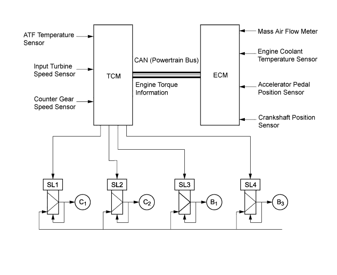
Control Function Shift Timing Control The TCM sends current to shift solenoid valves SL1, SL2, SL3, SL4, SL and/or SLU based on signals from various sensors, in order to shift the gears. Clutch to Clutch Pressure Control Controls the pressure applied directly to the No. 1 clutch (C1), No. 2 clutch (C2), No. 1 brake (B1) and No. 3 brake (B3) by actuating the shift solenoid valves (SL1, SL2, SL3 and SL4) in accordance with TCM signals.
Line Pressure Optimal Control Actuates shift solenoid valve SLT to control the line pressure in accordance with information from the TCM and the operating conditions of the transaxle. Powertrain Cooperative Control Controls both shift control and engine output control in an integrated way, achieving excellent shift characteristics and driveability. Artificial Intelligence Shift Control (AI-shift Control) Based on the signals from various sensors, the TCM determines the road conditions and the intention of the driver. Thus, an appropriate shift pattern is automatically determined, improving drivability. Coast Downshift Control To prevent engine speed from decreasing and thereby maintain the fuel cut, the TCM performs downshifts before the fuel cut ends. Lock-up Timing Control The TCM sends current to shift solenoid valves SL and SLU based on signals from various sensors to engage or disengage the lock-up clutch. Flex Lock-up Clutch Control Controls shift solenoid valve SLU, provides an intermediate mode between the on and off states of the lock-up clutch, and increases the operating range of the lock-up clutch to improve fuel economy. Multi-mode Automatic Transmission (with Shift Paddle Switch)
-
The TCM appropriately controls the automatic transaxle in accordance with the gear range selected using the shift lever or shift paddle switch (transmission shift switch assembly) while the shift lever is in M.
-
When the shift lever is in D, the driver can select a desired gear range using the shift paddle switch (transmission shift switch assembly).
Gear Hold Control Holds the gear position selected by the driver, unless the vehicle is decelerated and the shift lever or shift paddle switch (transmission shift switch assembly) is operated. Complete Lock-up Control In 2nd gear and higher, this control transmits engine output directly to the transaxle using the torque converter lock-up clutch. However, even in 2nd gear and higher, when engine speed is low, the control is not operated. High Response Upshift Control Achieves crisp and high response upshift using the clutch to clutch pressure control and powertrain cooperative control. Blipping Downshift Control Achieves smooth and quick downshift using the clutch to clutch pressure control and powertrain cooperative control. -
-
Clutch to Clutch Pressure Control
-
The clutch to clutch pressure control is used for shift control. As a result, shift control in 2nd gear or above can be performed without using a 1-way clutch, making the automatic transaxle lightweight and compact.
-
Based on the information about transaxle input and output speed, engine torque and other items, the TCM controls each clutch and brake in accordance with the optimum fluid pressure and timing, in order to shift the gears. The TCM changes gears using fluid pressure circuits which enable the No. 1 clutch (C1), No. 2 clutch (C2), No. 1 brake (B1) and No. 3 brake (B3) to be controlled independently, and using high flow SL1, SL2, SL3 and SL4 shift solenoid valves which directly control the line pressure. As a result, highly responsive and excellent shift characteristics have been achieved.
-
-
Line Pressure Optimal Control
-
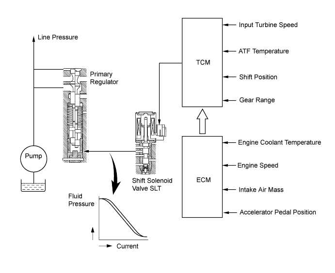
The line pressure is controlled using shift solenoid valve SLT.
-
Through the use of shift solenoid valve SLT, the line pressure is optimally controlled in accordance with the engine torque information, as well as with the internal operating conditions of the torque converter and the transaxle.
-
Accordingly, the line pressure can be accurately controlled in accordance with the engine output, traveling condition and ATF temperature, thus achieving smooth shift characteristics and optimizing the workload of the oil pump (reducing unnecessary parasitic losses).
-
-
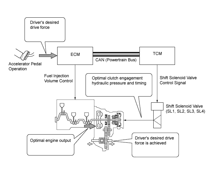
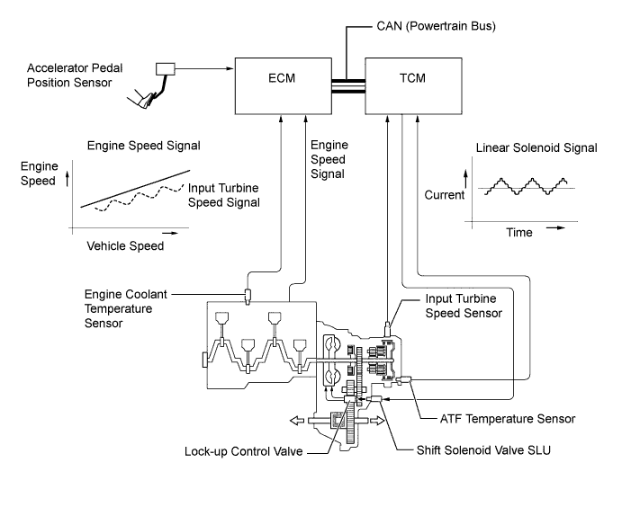
Powertrain Cooperative Control
-
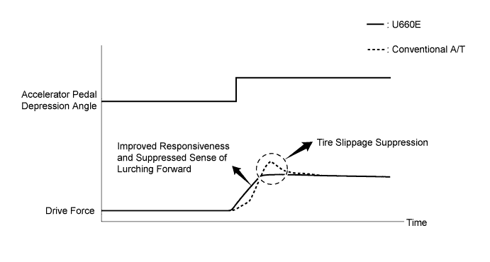
The engine output is optimally controlled using the fuel injection volume control in real time and in accordance with the transient force from the torque converter when the vehicle is launched. This achieves a suppressed sense of lurching forward, tire slippage suppression and improved responsiveness, ensuring excellent launch performance.
-
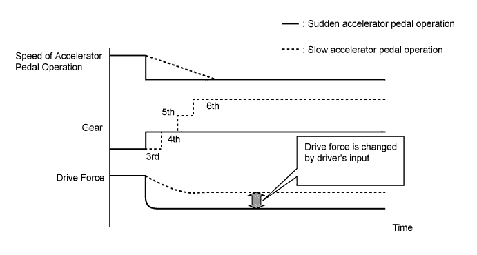
The TCM determines the gear that is to be selected when the accelerator pedal is released (released completely) in accordance with the way the accelerator pedal is released (suddenly or slowly) during deceleration. In this way, unnecessary upshifts are prevented during deceleration, matching the driver's intentions. In addition, unintended downshifts are prevented when accelerating the vehicle again, achieving smooth acceleration.
-
Quick response and shift shock reduction have been achieved through a cooperative control with the following controls:
-
Fuel injection volume control
-
Electronic control of the engagement and release speed of the clutch and brake hydraulic pressures
-
-
-
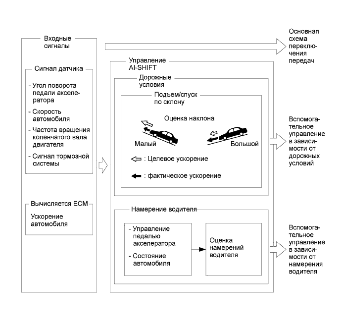
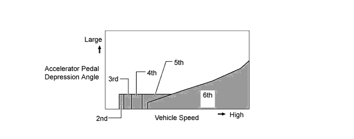
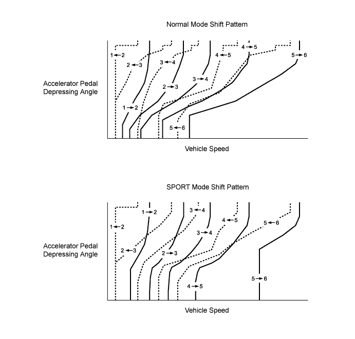
Artificial Intelligence Shift Control (AI-shift Control)
-
The automatic transaxle gear is determined by the shift pattern, which uses the vehicle speed and accelerator pedal depressing angle.
-
Additionally, AI-shift control enables the TCM to estimate the road conditions and the driver's intention in order to automatically control the shift pattern in the optimal manner. As a result, a comfortable ride has been achieved.
-
The AI-shift control includes road condition support control and driver's intention support control.
-
The AI-shift control determines optimal transaxle control based on input signals and automatically changes the shift pattern.
-
Under road condition support control, the TCM determines from the accelerator pedal depressing angle and the vehicle speed whether the vehicle is being driven uphill or downhill. To achieve the optimal drive force while driving uphill, this control prevents unnecessary upshifts. To achieve the optimal engine brake effect while driving downhill, this control automatically performs downshifts.
-
The driver's intention is estimated based on the accelerator pedal depressing angle and vehicle condition to switch to a shift pattern that is well-suited to the driver.
-
-
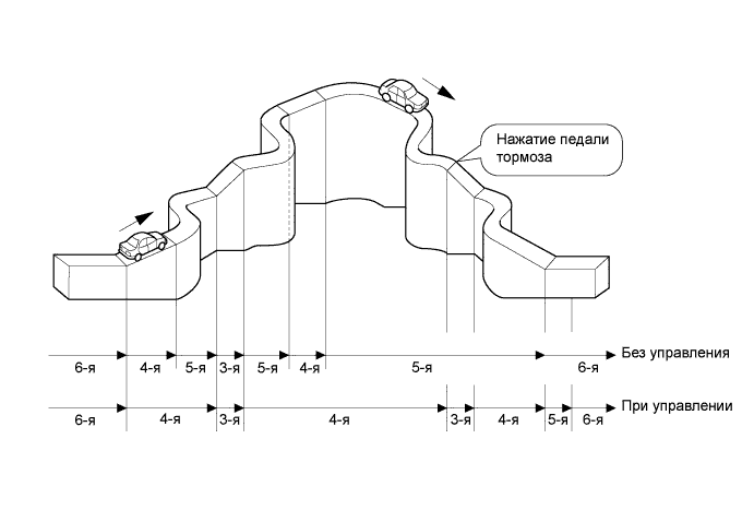
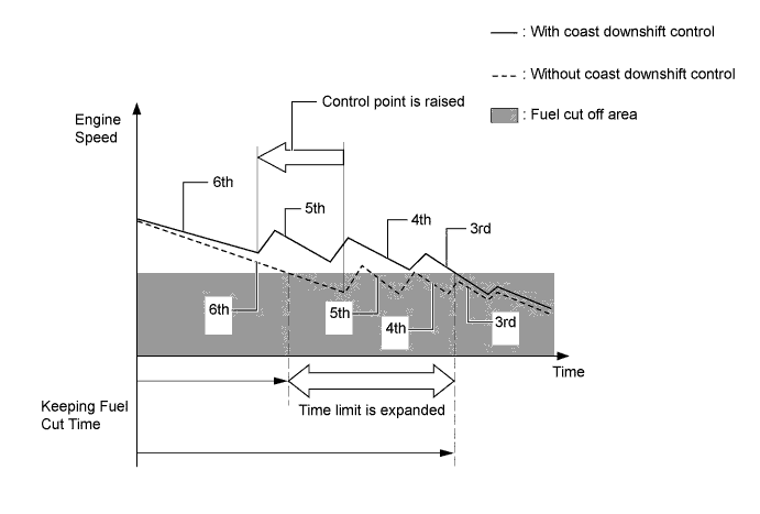
Coast Downshift Control
-
The TCM performs downshift control to help prevent the engine speed from decreasing, thus keeping fuel cut control operating for as long as possible. In this way, fuel economy is improved.
-
For this control, when the vehicle is in 6th gear and starts decelerating, the transaxle downshifts from 6th to 5th, 5th to 4th and 4th to 3rd before fuel cut control ends so that the fuel cut control can continue operating.
-
-
Lock-up Timing Control
-
The TCM uses lock-up timing control in order to improve the fuel consumption performance in 2nd or higher when the shift lever is in D or M.
Lock-up Timing Control Operation Gear Shift Lever Position D D (Shift Paddle Switch Operation) M D6 D5 D4 D3 D2 1st X X X X X X X 2nd ○ ○ ○ ○ ○ ○ ○ 3rd ○ ○ ○ ○ ○ - ○ 4th ○ ○ ○ ○ - - ○ 5th ○ ○ ○ - - - ○ 6th ○ ○ - - - - ○ Tech Tips
○: Available
X: Not available
-
-
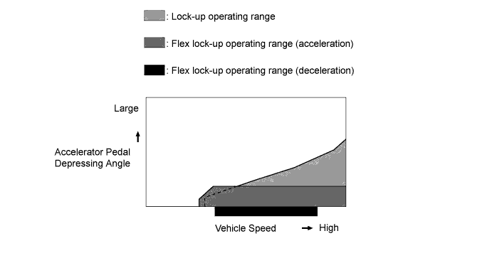
Flex Lock-up Clutch Control
-
During acceleration, the partial control of the power transmission between the lock-up clutch and torque converter greatly boosts the transmission efficiency in accordance with the driving conditions, improving the fuel economy.
-
Even when the vehicle is decelerating (the accelerator pedal is released), flex lock-up clutch control operates. Therefore, the fuel-cut area has been expanded and fuel-economy has been improved.
-
By allowing flex lock-up clutch control to continue operating during gearshifts, smooth torque transmission obtained. As a result, fuel economy and drivability have been improved.
-
For flex lock-up control, H infinity (H∞) control theory is used to achieve a high level of system stability and response to various characteristic changes.
Flex Lock-up Clutch Control Operation Gear Shift Lever Position D D (Shift Paddle Switch Operation) D6 D5 D4 D3 D2 1st X X X X X X 2nd ○ ○ ○ ○ ○ ○ 3rd ○*1 ○*1 ○*1 ○*1 ○ - 4th ○*2 ○*2 ○*2 ○*2 - - 5th ○*2 ○*2 ○*2 - - - 6th ○*2 ○*2 - - - - Tech Tips
○: Available
X: Not available
*1: Flex lock-up clutch control operates during deceleration only by coast downshift from 4th gear with deceleration flex lock-up.
*2: Flex lock-up clutch control also operates during deceleration.
-
-
Multi-mode Automatic Transmission
-
The driver can select the desired gear range by moving the shift lever to "+" (forwards) or to "-" (backwards) while the shift lever is in M (M mode). Also, the shift paddle switch (transmission shift switch assembly) can be used to change the gear range while the driver is holding the steering wheel. Thus, the driver is able to shift gears with a manual-like feel.
-
When the shift lever is in D (D mode), the driver can momentarily select a desired gear range by operating the shift paddle switch (transmission shift switch assembly). Automatic shifting (D mode) will be reinstated under the following conditions:
-
The vehicle has stopped.
-
The driver continues to push the shift paddle switch (transmission shift switch assembly) in the "+" direction longer than 1 second.
-
The driver depresses the accelerator pedal longer than a predetermined length of time.
-
-
When the vehicle is being driven at a speed that is higher than the maximum safe speed for a downshift, any attempt to shift to a lower range by operating the shift lever will not be performed. This is done in order to protect the automatic transaxle. In this case, the ECM sounds the buzzer in the combination meter assembly twice to alert the driver.
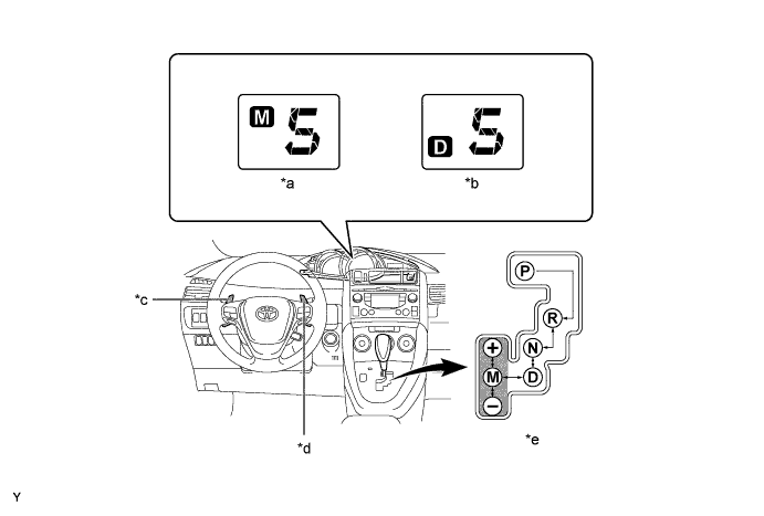
Text in Illustration *a 5th in M Mode *b 5th in D Mode *c Shift Paddle Switch (Transmission Shift Switch Assembly) "-" *d Shift Paddle Switch (Transmission Shift Switch Assembly) "+" *e M Mode - - -
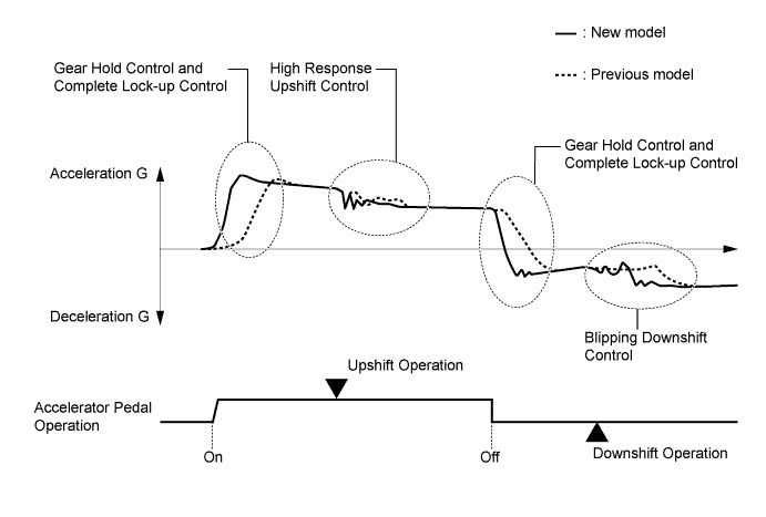
In M mode, the gear hold control, complete lock-up control, high response upshift control and blipping downshift control are used in order to improve response in accordance with the driver's operation of the accelerator pedal, shift lever, or shift paddle switch (transmission shift switch assembly), and to improve gear shift feeling.
-
Gear shifting will not be performed under gear hold control as long as the shift lever or shift paddle switch (transmission shift switch assembly) is not operated. This make it possible to make efficient use of highest engine speeds. However, if the vehicle speed drops, a downshift will be performed from the current gear to a gear appropriate for that speed. Also, when the ATF temperature is extremely high, upshift will be performed automatically.
-
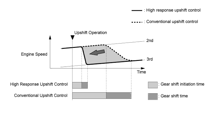
The high response upshift control achieves highly responsive upshift operation using the clutch to clutch pressure control, which regulates each clutch and brake quickly and precisely, and by the powertrain cooperative control, which optimally regulates engine torque during shifting.
-
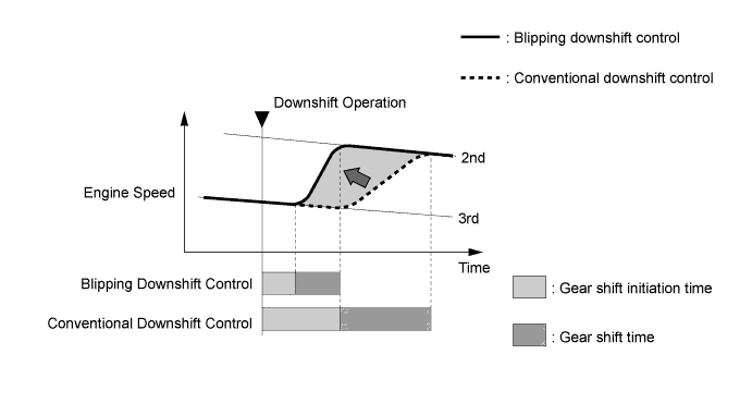
The blipping downshift control regulates each clutch and brake using the clutch to clutch pressure control, allowing them to be engaged smoothly and disengaged quickly. In addition, fuel injection volume is increased and engine speed is boosted by the powertrain cooperative control, thus ensuring engine brake force. In this way, a smooth and quick downshift is achieved.
-
-
-
FUNCTION
-
Pattern Select Switch Assembly
-
The driver can select 2 different settings for shift schedule and AI-shift control.
-
When the pattern select switch is on (SPORT mode), a more aggressive shift schedule and AI-shift tuning is selected for sporty driving.
-
-
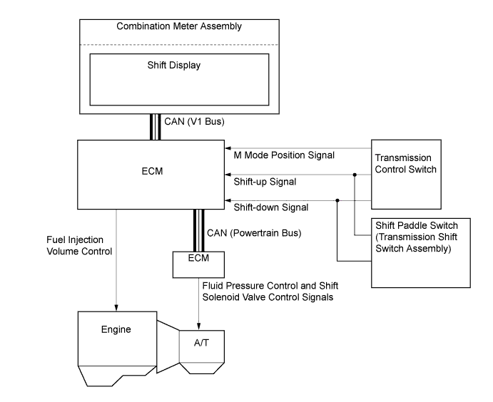
Gear Shift Indicator System
-
The Gear Shift Indicator system is a system to promote upshifting to the fuel-efficient and optimal gear ranges in accordance with the driving conditions such as the accelerator pedal opening and the vehicle speed, etc. when the vehicle is running while the shift lever is in M.
-
By driving in accordance with the upshifting recommendations indicated by the gear shift indicator in the combination meter assembly, the driver can enhance environmental performance, improve fuel economy and reduce exhaust gas emissions within the limits of engine performance.
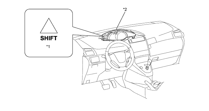
Text in Illustration *1 Gear Shift Indicator *2 Combination Meter Assembly
-
-
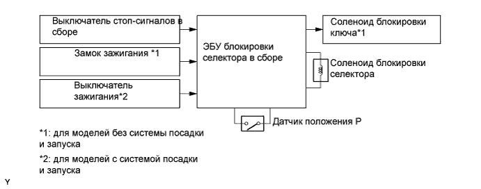
Shift Lock System
-
On the models without the entry and start system, the key interlock device prevents the key from being pulled out after the ignition switch has been turned off, unless the shift lever has been moved to P. Thus, the driver is urged to park the vehicle with the shift lever in P.
-
The shift lock mechanism prevents the shift lever from being moved to any position other than P, unless the ignition switch*1 is ON or the engine switch*2 is turned on (IG), and the brake pedal is depressed. This prevents the vehicle from starting off suddenly.
-
The shift lock ECU uses the P detection switch to detect the shift lever position, and receives input signals from the stop light switch assembly and ignition switch*1 or engine switch*2. Upon receiving these signals, the shift lock control ECU sub-assembly turns on the key interlock solenoid*1 and the shift lock solenoid in order to release the key interlock and shift lock.
-
*1: Models without entry and start system
-
*2: Models with entry and start system
-
-
A shift lock release button, which manually overrides the shift lock mechanism, is used.
-
-
-
CONSTRUCTION
-
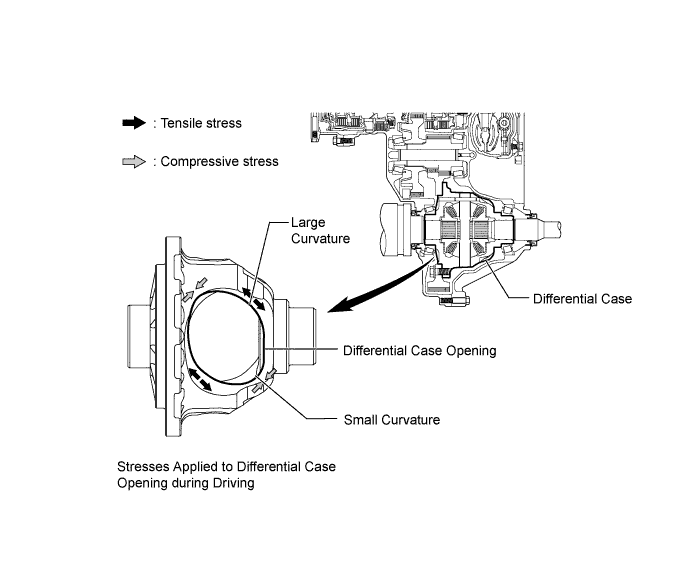
Differential Case
-
The curvature of the differential case opening, where tensile stress is concentrated during driving, is enlarged in order to moderate the stress concentration and enhance the torque tolerance of the differential case. As a result, a lightweight 2-pinion gear differential can be used.
-
-
Torque Converter Clutch Assembly
-
A compact, lightweight and high-capacity torque converter clutch assembly is used.
-
This torque converter clutch has optimally designed fluid passages and impeller configuration, resulting in substantially enhanced transmission efficiency to ensure good starting, acceleration and fuel economy.
-
Furthermore, a hydraulically operated lock-up mechanism which cuts power transmission losses caused by slippage at medium and high speeds is used.
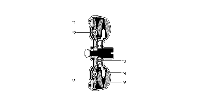
Text in Illustration *1 Lock-up Clutch *2 Lock-up Damper *3 1-way Clutch *4 Stator *5 Turbine Runner *6 Pump Impeller
-
-
Oil Pump Assembly
-
The oil pump is operated by the torque converter. It lubricates the planetary gear units and supplies operating fluid pressure for hydraulic control.
-
The pump cover is made of aluminum to reduce weight.
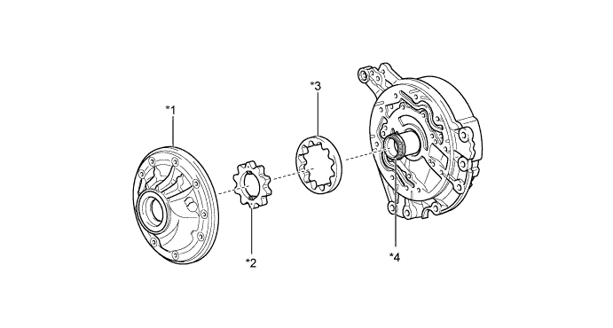
Text in Illustration *1 Oil Pump Body *2 Front Oil Pump Drive Gear *3 Front Oil Pump Driven Gear *4 Stator Shaft Assembly
-
-
Oil Strainer
-
A felt type oil strainer is used for its light weight, its excellent debris capturing ability and its increased reliability. This oil strainer is maintenance-free.
Text in Illustration *1 Oil Filter *2 Oil Strainer
-
-
ATF Filling Procedure
-
A special ATF filling procedure is used in order to improve the accuracy of the ATF level when the transaxle is being repaired or replaced. As a result, the oil filler tube and the oil level gauge used in the conventional automatic transmission have been discontinued, eliminating the need to inspect the fluid level as a part of routine maintenance.
-
This filling procedure uses a refill plug, an overflow plug, an ATF temperature sensor, and a D indicator. For details about the ATF filling procedure, refer to the VERSO Repair Manual.
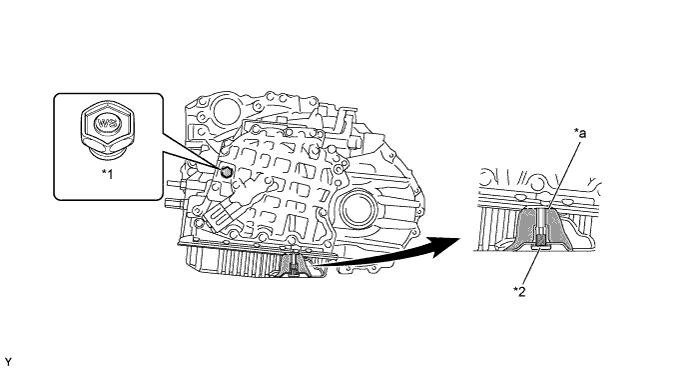
Text in Illustration *1 Refill Plug *2 Overflow Plug *a Proper Level - -
-
-
Planetary Gear Unit
-
A 6-speed configuration has been achieved by using 2 planetary gear units, creating a 6-speed automatic transaxle.
-
A Ravigneaux type planetary gear unit is used as the rear gear unit. The gear unit consists of pairs of sun gears (front and rear) and planetary pinion gears (long and short) with different diameters within a single planetary gear.
-
A centrifugal fluid pressure canceling mechanism is used in the No. 1 clutch (C1) and No. 2 clutch (C2) that are applied when shifting between 1st to 6th gears.
-
The shapes of the grooves in the clutches and brake linings have been optimized in order to reduce drag.
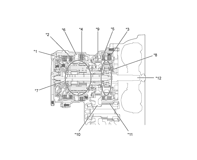
Text in Illustration *1 No. 1 Clutch (C1)
*2 No. 2 Clutch (C2)
*3 No. 1 Brake (B1)
*4 No. 2 Brake (B2)
*5 No. 3 Brake (B3)
*6 No. 1 1-way Clutch (F1)
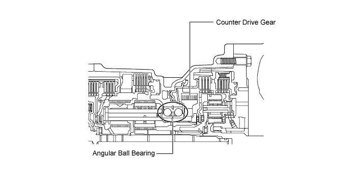
*7 Ravigneaux Planetary Gear Unit *8 Underdrive Planetary Gear Unit *9 Counter Drive Gear *10 Counter Driven Gear *11 Differential Drive Pinion *12 Input Shaft 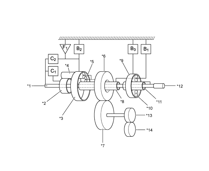
Text in Illustration *1 Intermediate Shaft *2 Rear Sun Gear *3 Ring Gear (Ravigneaux Planetary Gear) *4 Long Pinion Gear *5 Short Pinion Gear *6 Counter Drive Gear *7 Counter Driven Gear *8 Front Sun Gear *9 Ring Gear (Underdrive Planetary Gear) *10 Pinion Gear *11 Sun Gear *12 Input Shaft *13 Differential Drive Pinion *14 Ring Gear (Differential)
-
-
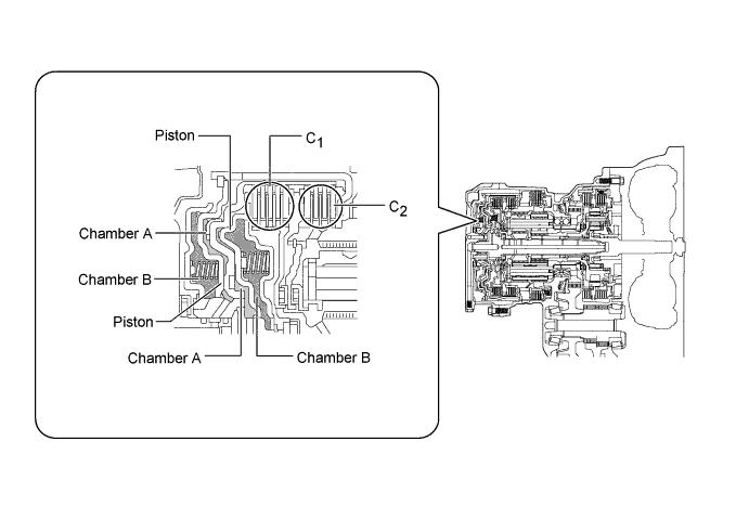
Centrifugal Fluid Pressure Canceling Mechanism
-
For the following reason, a centrifugal fluid pressure canceling mechanism is used on the No. 1 clutch (C1) and No. 2 clutch (C2):
-
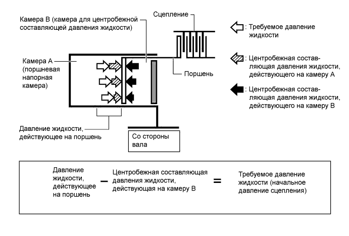
Clutch shifting operation is affected not only by the valve body controlling fluid pressure but also by centrifugal fluid pressure from the fluid that is present in the clutch piston oil pressure chamber (chamber A). The centrifugal fluid pressure canceling mechanism uses chamber B to reduce the effects of the centrifugal fluid pressure caused by the fluid in chamber A. As a result, smooth shifting with excellent response is achieved.
-
Chamber B is filled by fluid supplied to the shaft for lubrication. As a result of filling chamber B, the same amount of fluid pressure is present on both sides of the piston due to centrifugal force. This cancels the effects of fluid pressure on the piston caused by centrifugal force. Accordingly, it is not necessary to discharge the fluid through the use of a check ball, and highly responsive and smooth shifting characteristics are achieved.
-
-
Counter Drive Gear
-
Angular ball bearings are used to support the counter drive gear and the Ravigneaux planetary gear unit, reducing the rolling resistance and noise.
-
-
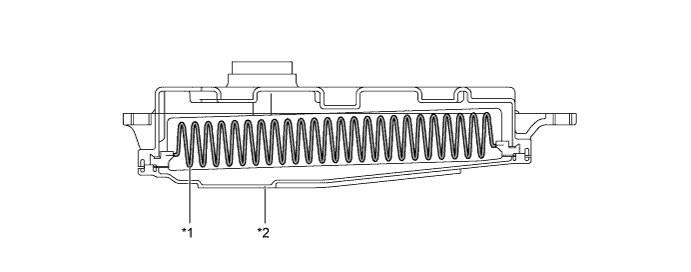
Clutch and Brake Pistons
-
2 types of pistons are used: a non-split piston that acts in the push direction for the No. 1 clutch (C1) operation, and a split piston that acts in the pull direction for the No. 2 clutch (C2) operation. These 2 types of pistons contribute to making the entire clutch structure compact.
-
When the split piston operates, clutch drag occurs due to rattling caused by the divided portion of the piston. However, by fitting springs on the circumference of the piston, this rattling is restrained and the occurrence of clutch drag is minimized.
-
By setting the piston for the No. 3 brake (B3) operation around the counter drive gear, the brake structure has been made more compact.
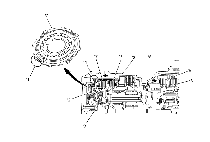
Text in Illustration *1 Spring *2 Piston (Split Type) *3 Piston (Non-split Type) *4 Divided Portion *5 Piston *6 Counter Drive Gear *7 No. 1 Clutch (C1)
*8 No. 2 Clutch (C2)
*9 No. 3 Brake (B3)
- -
-
-
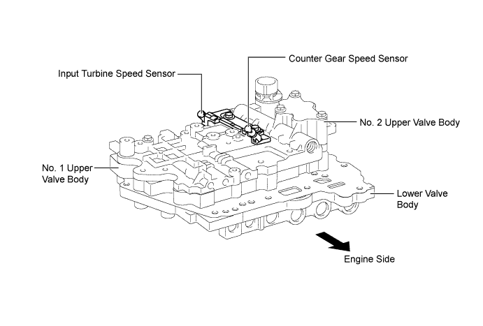
Valve Body Unit
-
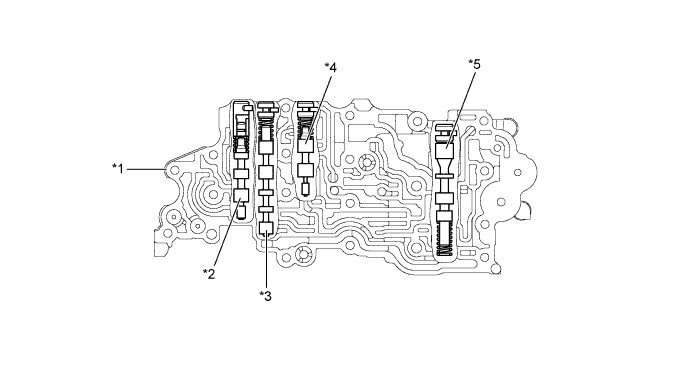
The valve body unit consists of a No. 1 upper valve body, a No. 2 upper valve body and a lower valve body and 7 shift solenoid valves (SL1, SL2, SL3, SL4, SLU, SLT, SL).
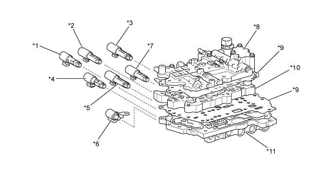
Text in Illustration *1 Shift Solenoid Valve SLU *2 Shift Solenoid Valve SL1 *3 Shift Solenoid Valve SL4 *4 Shift Solenoid Valve SLT *5 Shift Solenoid Valve SL2 *6 Shift Solenoid Valve SL *7 Shift Solenoid Valve SL3 *8 No. 2 Upper Valve Body *9 Plate *10 No. 1 Upper Valve Body *11 Lower Valve Body - - 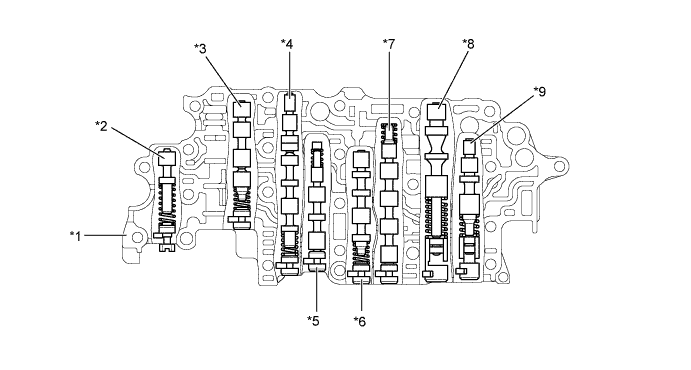
Text in Illustration *1 No. 1 Upper Valve Body *2 Solenoid Modulator Valve *3 B2Control Valve
*4 B2Apply Control Valve
*5 Clutch Apply Control Valve *6 Clutch Control Valve *7 Sequence Valve *8 Primary Regulator Valve *9 B1Apply Control Valve
- - 
Text in Illustration *1 No. 2 Upper Valve Body *2 Lock-up Control Valve *3 Lock-up Relay Valve *4 Reverse Sequence Valve *5 Secondary Regulator Valve - - 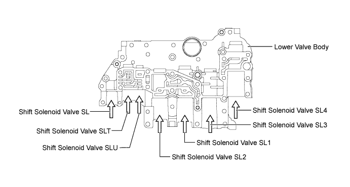
-
-
Shift Solenoid Valves SL1, SL2, SL3, SL4, SLU and SLT
-
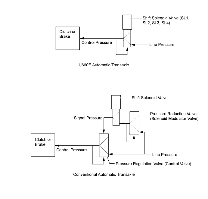
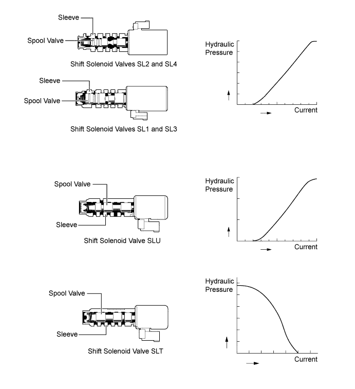
In order to provide a hydraulic pressure that is proportional to the current that flows to the solenoid coil, shift solenoid valves SL1, SL2, SL3, SL4, SLU and SLT linearly control the line pressure and clutch and brake engagement pressure based on the signals from the TCM.
-
Shift solenoid valves SL1, SL2, SL3 and SL4 are high flow linear solenoid valves that can supply more pressure than conventional ones. These shift solenoid valves control engagement elements by directly regulating the line pressure without using a pressure regulation valve (control valve) or a pressure reduction valve (solenoid modulator valve). Thus, the number of valves and the length of the valve body fluid passage have been reduced, the shifting response has been increased and shift shock has been minimized.
Function of Shift Solenoid Valves SL1, SL2, SL3, SL4, SLU and SLT Shift Solenoid Valve Function SL1 No. 1 clutch (C1) pressure control
SL2 No. 2 clutch (C2) pressure control
SL3 No. 1 brake (B1) pressure control
SL4 No. 3 brake (B3) pressure control
SLU
-
Lock-up clutch pressure control
-
No. 2 brake (B2) pressure control
SLT Line pressure control -
-
-
Shift Solenoid Valve SL
-
Shift solenoid valve SL is a 3-way solenoid valve.
-
A filter is provided at the tip of the solenoid valve to further improve operational reliability.
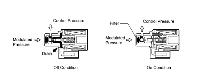
Function of Shift Solenoid Valve SL Shift Solenoid Valve Function SL
-
Switches the lock-up relay valve.
-
Switches the B2apply control valve and the reverse sequence valve.
-
-
-
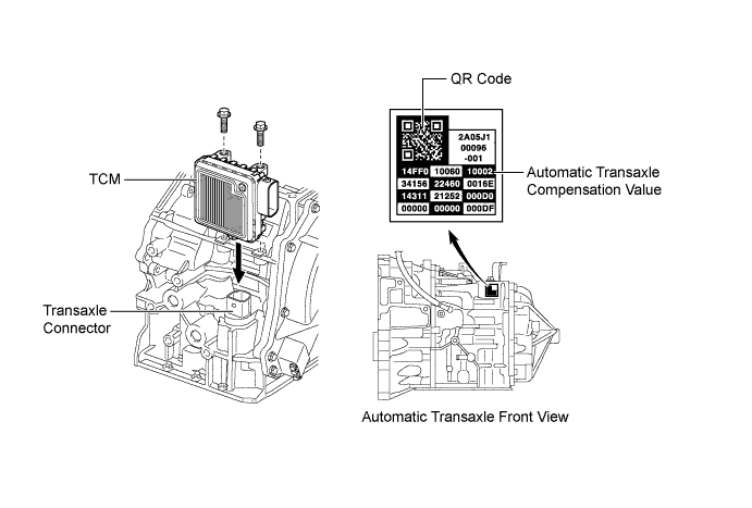
TCM
-
The TCM has been isolated from the ECM and directly fitted to the transaxle. Because of this, the wiring harness has been shortened, allowing weight to be reduced. All the solenoid valves and sensors used for automatic transaxle control are directly connected to the TCM through the connector located in front of the automatic transaxle.
-
The TCM maintains communication with the ECM through the Controller Area Network (CAN). Thus, engine control can be performed in coordination with ECT control.
-
A label, on which the automatic transaxle compensation values and Quick Response (QR) code are printed, is attached on the top of the automatic transaxle. The label contains encoded information about the characteristics of the automatic transaxle. When the automatic transaxle is replaced, allow the TCM to learn the characteristics of the automatic transaxle by inputting the automatic transaxle compensation values into the TCM using the intelligent tester II. In this way, the shift control performance is improved immediately after replacement of the automatic transaxle. For details, refer to the VERSO Repair Manual.
-
The QR code, which requires a special tool to read, is used at the vehicle assembly plant.
Tech Tips
What are Quick Response (QR) Codes?
-
QR code, a matrix symbology consisting of an array of nominally square cells, allows omni-directional, high-speed reading of large amounts of data.
-
QR codes encode many types of data such as numeric, alphanumeric, kanji, kana and binary codes. A maximum of 7089 characters (numeric) can be encoded.
-
QR codes (2D code) contain information in the vertical and horizontal directions, whereas bar codes only contain data in one direction. QR codes (2D code) hold considerably greater volumes of information than bar codes.
-
-
-
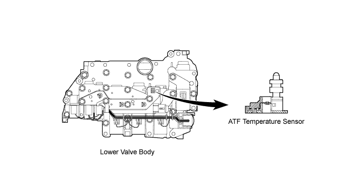
ATF Temperature Sensor
-
The ATF temperature sensor is installed in the transmission valve body assembly for direct detection of the fluid temperature.
-
The ATF temperature sensor is used for hydraulic pressure control. This sensor is used for fine-tuning the pressure used to apply clutches and brakes. This helps to ensure smooth shift quality.
-
-
ATF Pressure Switch
-
The ATF pressure switch is located in the output fluid passage of shift solenoid valve SLU, and it turns on and off in accordance with the output fluid pressure of shift solenoid valve SLU.
-
The TCM detects malfunctions in shift solenoid valve SLU used in lock-up control in accordance with the on or off signals from ATF pressure switch located in the SLU output fluid passage.
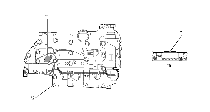
Text in Illustration *1 ATF Pressure Switch *2 Lower Valve Body *a Cross Section - -
-
-
Speed Sensors
-
The U660E automatic transaxle uses an input turbine speed sensor (for the NT signal) and a counter gear speed sensor (for the NC signal). Using these, the TCM can determine the timing of the shifting of the gears and appropriately control the engine torque and hydraulic pressure in response to the various conditions.
-
The input turbine speed sensor detects the input speed of the transaxle. The No. 2 clutch piston is used as the timing rotor for this sensor.
-
The counter gear speed sensor detects the speed of the counter gear. The counter drive gear is used as the timing rotor for this sensor.
-
A Hall type speed sensor consists of a magnet and a Hall IC. The Hall IC converts the changes in the magnetic flux density that occur through the rotation of the timing rotor into an electric signal, and outputs the signal to the TCM.
-
-
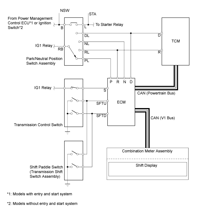
Park/Neutral Position Switch Assembly, Transmission Control Switch and Shift Paddle Switch (Transmission Shift Switch Assembly)
-
The TCM and ECM use the park/neutral position switch and transmission control switch to detect the shift lever position.
-
The park/neutral position switch sends R and D signals to both the TCM and ECM, and sends P and N signals to the ECM only.
-
The transmission control switch is installed inside the shift lock control unit assembly to inform the ECM of the shift lever position.
-
The shift paddle switch (transmission shift switch assembly) is installed in the steering wheel. The ECM detects the operation of the shift paddle switch (transmission shift switch assembly) "+" (upshift) or "-" (downshift) when the shift lever is in D or M.
-
-
Shift Control Mechanism
-
A gate type shift lever that uses a transmission control cable is used.
-
The shift control mechanism consists of a shift lock control unit assembly and a transmission control cable assembly.
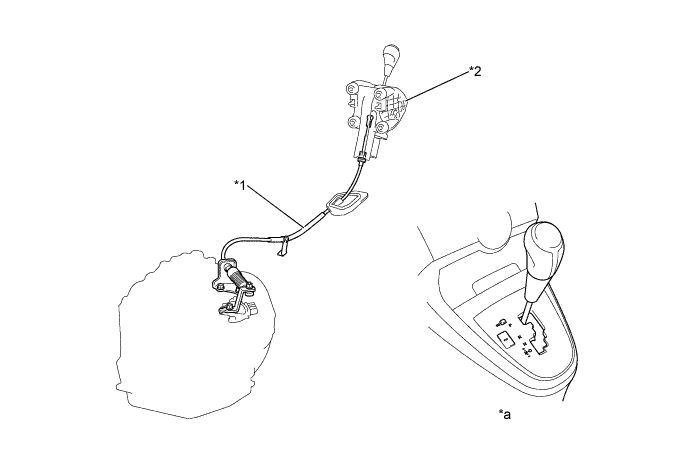
Text in Illustration *1 Transmission Control Cable Assembly *2 Shift Lock Control Unit Assembly *a Shift Pattern - -
-
-
-
OPERATION
-
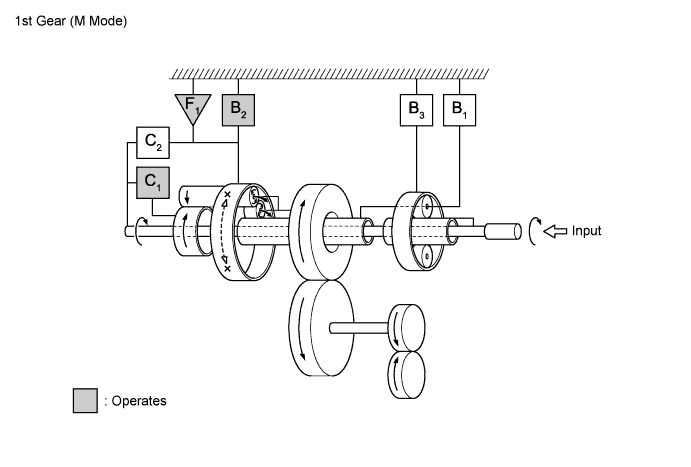
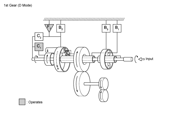
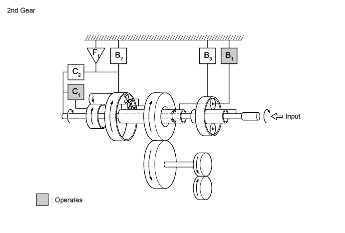
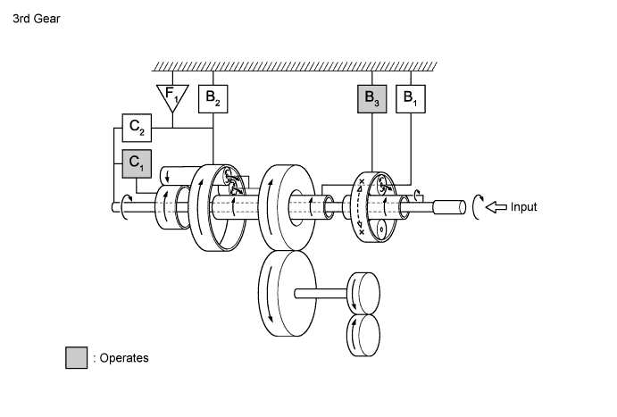
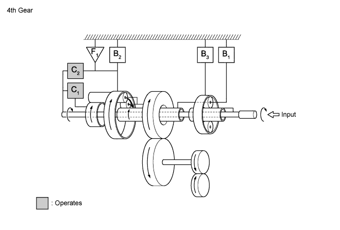
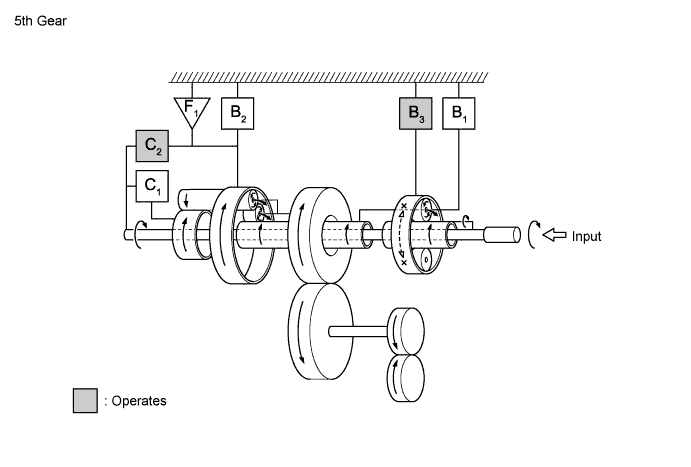
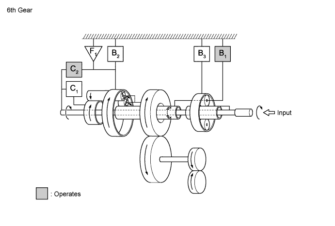
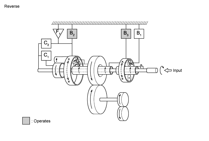
Transaxle Power Flow
Shift Solenoid Valves, Friction Engagement Components and 1-way Clutch Operation Shift Lever Position and Gear Range Shift Solenoid Valve Friction Engagement Component 1-way Clutch SL SL1 SL2 SL3 SL4 SLU C1
C2
B1
B2
B3
F1
P - ○ - - - - - - - - - - R ■ - - - ○ - - - - ○ ○ - N - ○ - - - - - - - - - - D 1st - ○ - - - - ○ - - (○) - ○ 2nd ○ ○ - ○ - ▲ ○ - ○ - - - 3rd ○ ○ - - ○ ▲ ○ - - - ○ - 4th ○ ○ ○ - - ▲ ○ ○ - - - - 5th ○ - ○ - ○ ▲ - ○ - - ○ - 6th ○ - ○ ○ - ▲ - ○ ○ - - - M6 6th ○ - ○ ○ - ▲ - ○ ○ - - - M5 5th ○ - ○ - ○ ▲ - ○ - - ○ - M4 4th ○ ○ ○ - - ▲ ○ ○ - - - - M3 3rd ○ ○ - - ○ ▲ ○ - - - ○ - M2 2nd ○ ○ - ○ - ▲ ○ - ○ - - - M1 1st - ○ - - - ○ ○ - - ○ - ○ Tech Tips
○: On
(○): During engine brake operation
▲: In accordance with flex lock-up
■: On while engaging, off after engaged
-: Not operation
-
-
FAIL-SAFE
-
The fail-safe function minimizes the loss of operability when an abnormality occurs in a sensor or a shift solenoid valve.
Fail-safe Control List Malfunction Part Function Input Turbine Speed Sensor Shifting to only either the 1st or 3rd gear is allowed. Counter Gear Speed Sensor
-
The counter gear speed is detected through the signals from the skid control ECU.
-
Shifting between the 1st and 4th gears is allowed.
ATF Temperature Sensor Shifting between the 1st and 4th gears is allowed. TCM Power Supply (Voltage is Low)
-
When the vehicle is being driven in 6th gear, the transaxle is fixed in 6th gear.
-
When being driven in any of the 1st to 5th gears, the transaxle is fixed in 5th gear.
Shift Solenoid Valves SL1, SL2, SL3 and SL4 The current to the failed shift solenoid valve is cut off and control is effected by operating the other shift solenoid valves with normal operation. For details, refer to the VERSO Repair Manual. -
-
-
DIAGNOSIS
-
When the TCM detects a malfunction, the TCM records the malfunction and memorizes the information related to the fault. Furthermore, the TCM illuminates or blinks the MIL in the combination meter to inform the driver.
-
The TCM will also store the Diagnostic Trouble Codes (DTCs) of the malfunctions. The DTCs stored in the TCM are output to the Global TechStream (GTS) via the ECM and the DLC3.
-
For details, refer to the VERSO Repair Manual.
-