LIGHTING SYSTEM DETAILS
-
FUNCTION OF MAIN COMPONENTS
-
Daytime Running Light System
Component Function Main Body ECU The main body ECU receives various signals and illuminates the low beams. Headlight Dimmer Switch Assembly Light Control Switch The light control switch outputs a light control signal and transmits it to the main body ECU. ECM The ECM outputs an engine speed signal and transmits it to the main body ECU. -
Automatic Light Control System
Component Function Main Body ECU The main body ECU receives various signals and illuminates the headlights, taillights, clearance lights, and license plate lights. Headlight Dimmer Switch Assembly Light Control Switch The light control switch transmits an AUTO position signal to the main body ECU. Rain Sensor The rain sensor detects the ambient light level. -
HID Headlight System
Component Function Main Body ECU The main body ECU receives the HEAD position signal and transmits a signal to the light control ECU. Headlight Dimmer Switch Assembly Light Control Switch The light control switch transmits a HEAD position signal to the main body ECU. Headlight Unit Light Control ECU The light control ECU transforms battery voltage to a high voltage of up to 30000 V and applies it to the discharge bulbs in order to illuminate them. Discharge Bulb The discharge bulb light shines ahead over a broader area and further forward, increasing the area visible to the driver. -
Automatic Headlight Beam Level Control System
Component Function Headlight Leveling ECU Assembly The headlight leveling ECU assembly receives various signals, calculates the target lighting angle, and actuates the headlight leveling motor. Headlight Unit Headlight Leveling Motor
-
Based on the signals received from the headlight leveling ECU assembly, the motors move the reflectors in the headlights.
-
Uses a step motor to precisely regulate the angle of the reflectors.
Rear Height Control Sensor Sub-assembly RH Detects the height of the vehicle. Main Body ECU Transmits the headlight status signal. Combination Meter Assembly
-
If the system malfunctions, the meter ECU alerts the driver by blinking the automatic headlight beam level control system warning light in accordance with the signal from the headlight leveling ECU assembly.
-
Transmits the vehicle speed signal to headlight leveling ECU assembly.
-
-
Manual Headlight Beam Level Control System
Component Function Headlight leveling switch The level of the headlight can be adjusted between 0 and 5, and a switch level status signal is sent to the actuator. Actuator Actuates in accordance with signals from the headlight leveling switch and moves the reflector up and down. -
Follow Me Home Function System
Component Function Main Body ECU Receives a light control signal and illuminates the headlights, clearance lights and taillights. Headlight Dimmer Switch Assembly Light Control Switch Outputs a light control signal and transmits it to the main body ECU.
-
-
OPERATING CONDITION
-
Daytime Running Light System
-
The daytime running light system is enabled when the conditions given below are met:
Condition Ignition switch (engine switch*) is ON. Light control switch OFF or AUTO position (when taillight is not being controlled by the automatic light control). Engine is running. The parking brake switch is off.
-
*: Models with entry and start system
-
-
-
-
FUNCTION
-
Daytime Running Light System
-
The daytime running light system is controlled by the main body ECU. The main body ECU illuminates the daytime running light.
-
-
Automatic Light Control System
-
When the light control switch is in the AUTO position, the rain sensor detects the ambient light level and automatically turns the headlights, taillights, clearance lights, and license plate lights on or off accordingly.
-
This system is controlled by the main body ECU.
-
-
Light Automatic Turn-off System
-
The light automatic turn-off system is controlled by the main body ECU.
-
This system has the following functions:
Switch Position Outline TAIL HEAD AUTO - - ○ While the lights (headlight, front fog light, rear fog light and taillight) are turned on, this system automatically turns them off when the ignition switch (engine switch*) is turned off. ○ ○ - While the lights (headlights, front fog lights, rear fog light and taillights) are turned on, this system automatically turns off only the headlights and the front fog lights when the ignition switch (engine switch*) is turned off.
-
*: Models with entry and start system
-
-
-
Follow Me Home Function System
-
The follow me home function system is controlled by the main body ECU.
-
When approximately 30 seconds elapse after all of the following conditions are met, the high beam headlights turn off:
-
The ignition switch (engine switch*) is off.
-
The light control switch is in the AUTO position or off position.
-
The headlight dimmer switch assembly is in the pass position, then neutral position.
-
*: Models with entry and start system
-
-
-
HID Headlight System
-
The HID headlight system consists of discharge bulbs and light control ECUs.
-
Light control ECU transforms the voltage that is input from the battery to a high voltage of up to 30000 V and applies it to the discharge bulbs in order to illuminate them.
-
A fail-safe function is provided as a countermeasure against the high voltage generated when a problem occurs in the headlight system.
-
-
Automatic Headlight Beam Level Control System
-
The automatic headlight beam level control system mainly consists of the headlight leveling ECU assembly, rear height control sensor RH, and 2 headlight leveling motors.
-
The headlight leveling ECU assembly calculates changes in the vehicle posture based on the signals from the rear height control sensor sub-assembly RH.
-
Following this, the ECU controls the headlight leveling motor based on this information, in order to change the headlight reflector angle.
-
Initial Set Control
When the engine is started, the headlight leveling ECU assembly drives the headlight leveling motor, moves the headlight reflector to the lower limit position and returns it to the proper position. The headlight leveling ECU assembly thus assesses the position of the headlight for reference control.
-
-
-
CONSTRUCTION
-
HID Headlight System
-
Discharge Bulb
Instead of the filament contained in an incandescent bulb, a discharge bulb contains an arc tube, which is filled with xenon gas and metal halide.
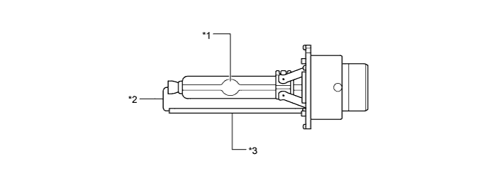
Text in Illustration *1 Arc Tube *2 Lead Wire *3 Ceramic Pipe - - -
Discharge bulbs have the following advantages:
-
The light emitted by the bulb is close in color to sunlight. The light shines ahead over a broader area and further forward, increasing the area visible to the driver.
-
Less power is consumed.
-
-
-
-
FAIL-SAFE
-
HID Headlight System
-
The light control ECU stops illuminating the HID headlights when any of the following abnormalities are detected:
Condition Content Open in output side circuit
-
Stops illuminating the headlights.
-
Keeps the headlights off until the power is reinstated (by turning the light control switch from off to the head position).
Short between output terminals
-
Stops illuminating the headlights.
-
Keeps the headlights off until the power is reinstated (by turning the light control switch from off to the head position).
Leak between output terminal and body ground
-
Stops illuminating the headlights.
-
Keeps the headlights off until the power is reinstated (by turning the light control switch from off to the head position).
Excessively low output voltage
-
Stops illuminating the headlights when the output voltage becomes too low (31 +/- 3 V or less).
-
Keeps the headlights off until the power is reinstated (by turning the light control switch from off to the head position).
Excessively high output voltage
-
Stops illuminating the headlights when the output voltage becomes too high (69 +/- 4 V or more).
-
Keeps the headlights off until the power is reinstated (by turning the light control switch from off to the head position).
Excessively high input voltage
-
Stops illuminating the headlights when the input voltage becomes too high (20 +/- 3 V or more).
-
Illuminates the headlights again when the voltage returns to the operating voltage range (10 to 16 V).
Low input voltage
-
Stops illuminating the headlights when the input voltage becomes too low (below 6 V).
-
Illuminates the headlights again when the voltage returns to the operating voltage range (10 to 16 V).
-
-
-
Automatic Headlight Beam Level Control System
-
If the headlight leveling ECU assembly detects a malfunction in the automatic headlight beam level control system, it will take the actions indicated in the table below:
Trouble Area Condition (Fail-safe Control for Automatic Headlight Beam Level Control) Automatic Headlight Beam Level Control System Warning Light Height Control Sensor Signal Malfunction
-
Stops the operation after returning to initial position (fails at higher than initial position).
-
Stops the operation in current condition (fail at lower than initial position).
Blinks -
-
-
-
DIAGNOSIS
-
Automatic Headlight Beam Level Control System
-
If the headlight leveling ECU assembly detects a malfunction in the automatic headlight beam level control system, the headlight leveling ECU assembly blinks the automatic headlight beam level control system warning light. At the same time, the Diagnostic Trouble Codes (DTCs) are stored in memory. The DTCs can be read by use of the intelligent tester II. For details, refer to the Repair Manual.
-
-