POWER STEERING SYSTEM DETAILS
-
FUNCTION OF MAIN COMPONENTS
Component Function Steering Column Assembly Power Steering Motor Generates power assist in accordance with a signal received from the power steering ECU assembly. Rotation Angle Sensor (Built into Power Steering Motor) Outputs the rotation angle of the power steering motor to the power steering ECU assembly. Reduction Mechanism Reduces the speed of the power steering motor through the use of a worm gear and a wheel gear and transmits it to the column shaft. Power Steering Torque Sensor Detects the amount of twist of the torsion bar. Based on the torque applied to the torsion bar, the sensor creates an electrical signal, and outputs this signal to the power steering ECU assembly.. Combination Meter Assembly Power Steering Warning Light Lights up to alert the driver when the power steering ECU assembly detects a malfunction in the EPS system. Power Steering ECU Assembly Actuates the power steering motor mounted on the steering column assembly to provide power assist, based on the signals received from various sensors and ECUs. ECM Outputs the engine speed signal to the power steering ECU assembly. Skid Control ECU
-
Outputs the vehicle speed signal to the power steering ECU assembly.
-
Requests steering torque assist during steering cooperative control.
Air Conditioning Amplifier Assembly Receives a signal from the power steering ECU assembly to limit the electrical usage. Engine Stop and Start ECU* When the vehicle is in the idling stop condition, the engine stop and start ECU supplies electrical power to the power steering ECU assembly.
-
*: Models with 1WW engine
-
-
SYSTEM CONTROL
Controls of EPS System Control Outline Basic Control Calculates the assist current and assist direction from the steering torque value and the vehicle speed, and actuates the power steering motor. Inertia Compensation Control Ensures the starting movement of the power steering motor when the driver starts to turn the steering wheel. Friction Compensation Control Reduces steering wheel operation friction, improving steering feeling. Recovery Control During the short interval between the time the driver fully turns the steering wheel and the wheels try to recover, this control assists the recovery force. Damper Control Regulates the amount of assist when the driver turns the steering wheel while driving at high speeds, thus damping the changes in the yaw rate of the vehicle body. System Overheat Protection Control Estimates the power steering motor temperature based on the amperage and the current duration. If the temperature exceeds the standard, it limits the amperage to prevent the power steering motor from overheating. EPS Electric Load Control When the power steering ECU assembly detects a decrease in battery voltage, it sends a load control demand to the air conditioning amplifier assembly in order to limit electrical usage.
The air conditioning amplifier assembly limits operation of the rear window defogger, quick heater assembly*1, and mirror heater*2 until the air conditioning amplifier assembly releases the limitation demand.
-
*1: Models with quick heater assembly
-
*2: Models with mirror heater
-
Basic Control
-
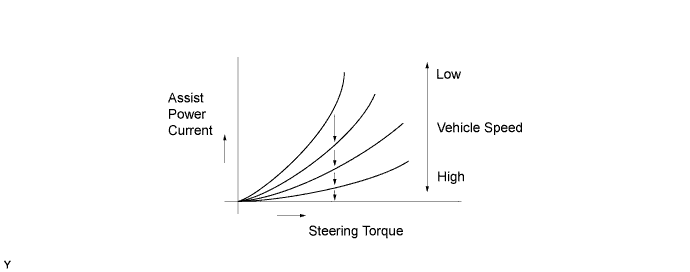
The power steering ECU assembly receives the vehicle speed signal and signals from various sensors. Based on these signals, the power steering ECU assembly judges the current vehicle condition, and determines the assist current to be applied to the power steering motor.
-
The diagram below describes the relationship between the steering torque and the assist power current.
-
-
EPS Electric Load Control
-
EPS electric load control stops the operation of the rear window defogger, quick heater assembly*1, and mirror heater*2 if the steering wheel is turned when the battery voltage is low. This enables the EPS system to ensure its power supply even if the battery is low.
-
*1: Models with quick heater assembly
-
*2: Models with mirror heater
-
-
The power steering ECU assembly detects the battery voltage, and if the voltage drops to approximately 10 V, it sends an electrical load control request to the air conditioning amplifier assembly.
-
The EPS electrical load control is performed as shown below:
Control Start Conditions EPS electrical load control starts when both of the following conditions are met:
-
Battery voltage is 10 V or less.
-
Steering wheel is being turned.
Control Cancellation Conditions EPS electrical load control cancels when both of the following conditions are met:
-
Steering wheel is not being turned.
-
Battery voltage has recovered to more than 12 V.
-
-
-
-
CONSTRUCTION
-
Steering Gear Assembly
-
Operability has been improved through a lightweight, compact rack and pinion type steering gear assembly.
-
A light weight has been achieved through a unified aluminum housing unit.
-
To keep the steering rigidity, the steering gear assembly is assembled in the front suspension cross member sub-assembly directly without elastic material.
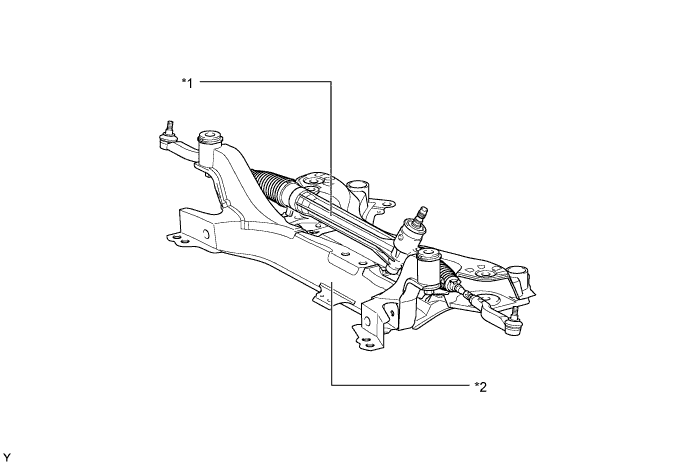
Text in Illustration *1 Steering Gear Assembly *2 Front Suspension Cross member Sub-assembly
-
-
Steering Column Assembly
-
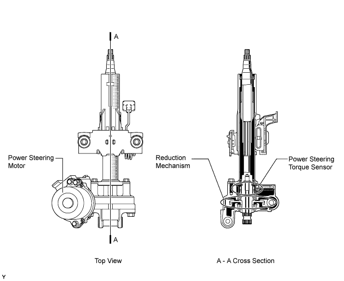
The steering column assembly includes a power steering motor, reduction mechanism, and power steering torque sensor.
-
-
Power Steering Motor
-
A low inertia, low noise, and high power output motor is used.
-
The operating range of the power steering motor is 9 V to 16 V.
-
The power steering motor consists of the rotor, stator, motor shaft and rotation angle sensor.
-
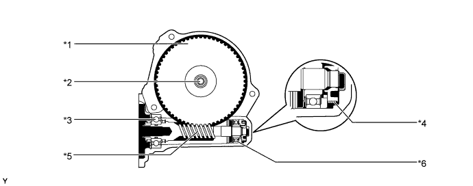
The torque generated by the power steering motor is transmitted via the joint to the worm gear. This torque is then transmitted via the wheel gear to the column shaft.
-
The rotation angle sensor consists of the resolver sensor, which excels in reliability and durability. The rotation angle sensor detects the rotation angle of the power steering motor and outputs it to the power steering ECU assembly. As a result, it ensures efficient EPS control.
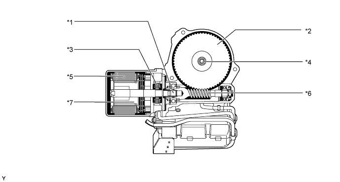
Text in Illustration *1 Motor Shaft *2 Wheel Gear *3 Rotation Angle Sensor *4 Column Shaft *5 Stator *6 Worm Gear *7 Rotor - -
-
-
Reduction Mechanism
-
This mechanism reduces the speed of the power steering motor via the worm gear and the wheel gear, and transmits it to the column shaft.
-
The wheel gear is made of a high strength, low friction, and low wear plastic material, to achieve low noise and a lightweight construction.
-
A worm gear supported by ball bearings is used. Also, a spring is provided to ensure the optimal meshing of the gears at all times.
Text in Illustration *1 Wheel Gear *2 Column Shaft *3 Ball Bearing *4 Spring *5 Worm Gear *6 Ball Bearing
-
-
Power Steering Torque Sensor
-
The power steering torque sensor is built into the steering column assembly. The power steering torque sensor consists of a sleeve, a stub shaft and 2 detection coils.
-
The sleeve is mounted on the input shaft, and the stub shaft is mounted on the output shaft. The input shaft and the output shaft are joined by the torsion bar. The detection coils are placed on the outside of the sleeve to complete an excitation circuit without making contact.
-
When the steering wheel is turned, the twist that is generated in the torsion bar creates a relative displacement between the sleeve and the stub shaft. The torque sensor outputs this change as an electrical signal to the power steering ECU assembly.
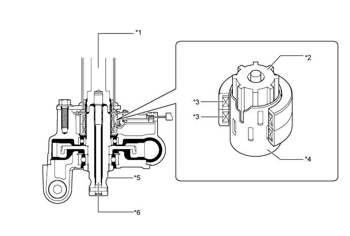
Text in Illustration *1 Input Shaft *2 Stub Shaft *3 Detection Coil *4 Sleeve *5 Output Shaft *6 Torsion Bar
-
-
-
OPERATION
-
Steering Torque and Steering Direction Detection
-
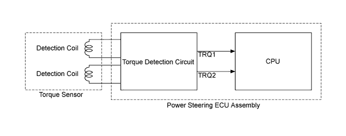
The torque detection circuit built in the power steering ECU assembly calculates the torque sensor 1 output (TRQ1) and the torque sensor 2 output (TRQ2) in accordance with the signals from the 2 detection coils of the torque sensor.
-
The power steering ECU assembly detects the steering torque and the steering direction in accordance with TRQ1 and TRQ2.
-
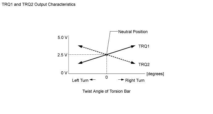
When the driver does not turn the steering wheel, TRQ1 and TRQ2 output a specified voltage (approximately 2.5 V). As long as the specified voltage is output, the power steering ECU assembly determines that steering torque is not being generated.
-
When the driver turns the steering wheel to the right or left, TRQ1 and TRQ2 changes as shown in the graph below. Based on the changes, the power steering ECU assembly determines the steering torque and steering direction input by the driver.
-
-
-
FAIL-SAFE
-
Fail-safe operation modes are as follows:
Detection Item Fail-safe Power Steering Torque Sensor Malfunction Disables the assist. Power Steering Motor Overheat Limits the assist force. Power Steering Motor Short (Including Drive System Malfunction) Disables the assist. Rotation Angle Sensor (Built into Power Steering Motor) Malfunction Disables the assist. Power Steering ECU Assembly Internal Temperature Sensor Malfunction Limits the assist force. Power Steering ECU Assembly System Malfunction Disables the assist. Vehicle Speed and Engine Speed Signal Malfunction Limits the assist force. Power Supply Voltage Malfunction Pauses the assist. (Provides normal assist after the voltage recovers.)
-
-
DIAGNOSIS
-
If the power steering ECU assembly detects a malfunction in the EPS system, the power steering ECU assembly lights up the power steering warning light in order to alert the driver. At the same time, Diagnostic Trouble Codes (DTCs) are stored in memory.
-
The DTCs can be read by connecting the Global TechStream (GTS) to the DLC3. For details, refer to the Repair Manual.
-