MANUAL TRANSAXLE SYSTEM DETAILS
-
FUNCTION
-
Gear Shift Indicator System
-
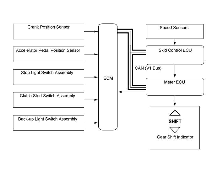
In the gear shift indicator system, the ECM calculates an environmentally favorable shift position based on the vehicle conditions, and makes a request to the meter ECU to indicate "upshifting or downshifting". Then, the gear shift indicator in the combination meter gives a shifting recommendation to the driver.
-
The ECM determines the actual gear position based on the signals from the crank position sensor and speed sensors, and the target gear position based on the signals from the accelerator pedal position sensor and speed sensors.
-
By driving in accordance with the shift change recommendations indicated by the gear shift indicator, the driver can enhance environmental performance, improve fuel economy and reduce exhaust gas output within limits of engine performance.
Control of Gear Shift Indicator System Control Outline System Start Checks the bulb of the indicator lights from the time the ignition switch (engine switch*) is turned to ON until the engine is started. Shifting Recommendation Control Calculates an environmentally favorable shift position based on the driving conditions of the vehicle, and gives a shifting recommendation. Shift Control in Uphill Traveling Prevents unnecessary shifting instructions by estimating the gradient of the road based on the driving conditions. Provides shift position instructions that enable the vehicle to attain the proper drive force. Delta Throttle Accelerate Control Determines a deceleration request when the driver releases the accelerator pedal suddenly. Thus, this control will not provide a shift-up instruction. However, it will provide a shift-up recommendation to protect the engine if the engine speed is high.
-
*: Models with entry and start system
-
-
The gear shift indicator system will not effect control while the vehicle is being driven in reverse.
-
The gear shift indicator system will not effect control while the vehicle is stopped or the clutch is not engaged while shifting.
-
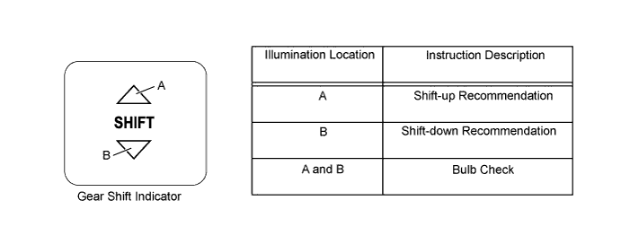
Upon receiving a shift instruction request from the ECM, the meter ECU will illuminate the indicator light.
-
The 2 indicator lights illuminate simultaneously during a bulb check.
-
-
-
CONSTRUCTION
-
Gear Layout
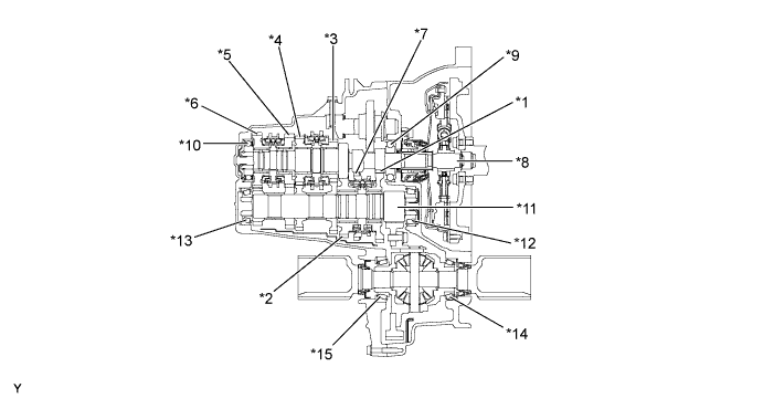
Text in Illustration *1 1st Gear *2 2nd Gear *3 3rd Gear *4 4th Gear *5 5th Gear *6 6th Gear Sub-assembly *7 Reverse Gear *8 Input Shaft *9 Front Input Shaft Bearing *10 Rear Input Shaft Radial Ball Bearing *11 Output Shaft *12 Front Output Shaft Bearing *13 Rear Output Shaft Bearing *14 Front Differential Case Front Tapered Roller Bearing *15 Front Differential Case Rear Tapered Roller Bearing - - -
Transmission Oil Separator
-
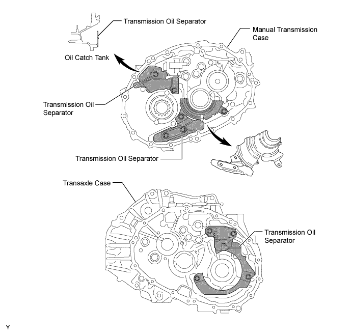
The transmission oil separator prevents the oil in the sump from being directly mixed by the output gears and differential ring gear.
-
An oil catch tank is formed in the space between the manual transmission case and the transmission oil separator located in the upper area of the differential ring gear side, thus reducing energy losses caused by oil mixing.
-
-
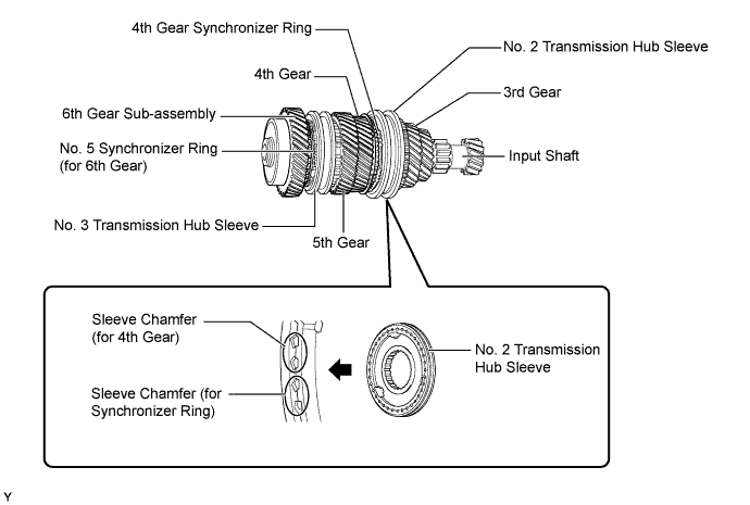
Synchromesh Mechanism
-
The No. 2 transmission hub sleeve has a 2-step sleeve chamfer structure. This reduces the amount of time needed for the gears to engage after synchronizing, thus improving shift feeling.
-
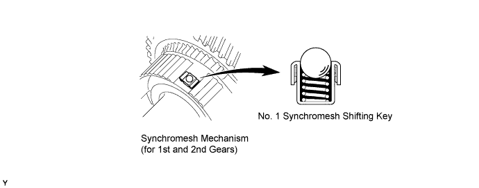
The ball and spring in the synchromesh shifting key have been combined into one unit, thus ensuring the stable position of the synchromesh shifting key and improving shift feeling.
-
-
Shift Mechanism
-
The shift mechanism consists of an outer No. 1 shift lever, an outer select lever, a shift and select lever shaft assembly, 3 gear shift fork shaft assemblies, a reverse shift arm bracket assembly, and a reverse shift fork.
-
The distances between the shift and select lever shaft assembly and each gear shift fork shaft assembly, and the distance between the shift fork and shift fork shaft have been shortened. This reduces sliding resistance, thus improving shift feeling.
-
The shape of the shift fork has been made symmetrical to improve shift feeling.
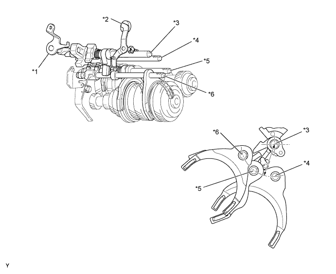
Text in Illustration *1 Outer Select Lever *2 Outer No. 1 Shift Lever *3 Shift and Select Lever Shaft Assembly *4 No. 1 Gear Shift Fork Shaft Assembly *5 No. 2 Gear Shift Fork Shaft Assembly *6 No. 3 Gear Shift Fork Shaft Assembly -
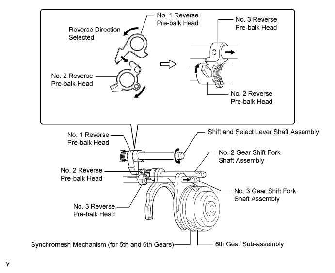
A pre-synchronizing system is used. While reverse is selected, the synchromesh mechanism of the 6th gear is activated, thus preventing gear noise when shifting into reverse gear.
-
-
Shift Control Mechanism
-
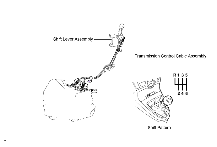
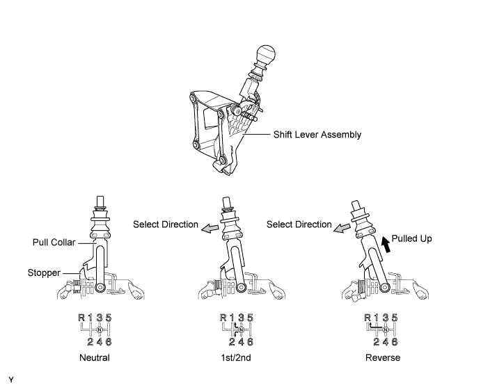
A pull collar type shift lever assembly, which is equipped with an inhibit mechanism, is used.
-
The shift control mechanism consists of a shift lever assembly and a transmission control cable assembly.
-
A stopper is provided on the 1st/2nd side, so that the pull collar must be pulled upward in order to shift into reverse. This reduces the amount of shift effort and ensures a precise shifting operation.
-
-