MANUAL TRANSAXLE SYSTEM DETAILS
-
FUNCTION
-
Gear Shift Indicator System
-
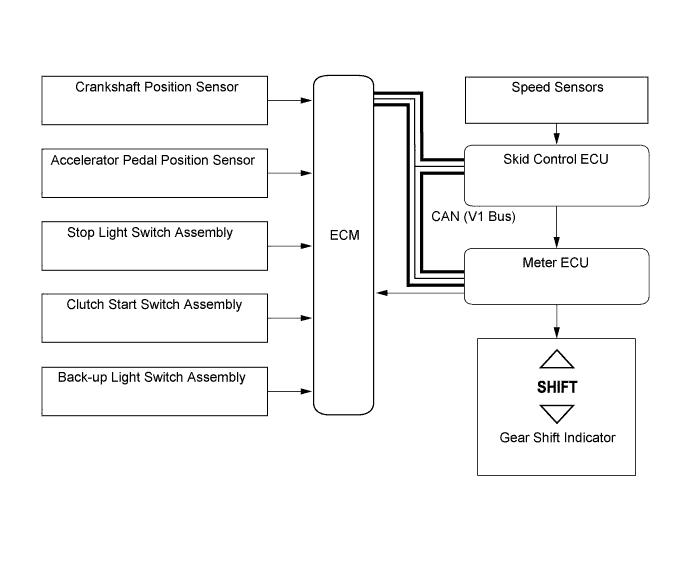
In the gear shift indicator system, the ECM calculates an environmentally favorable shift position based on the vehicle conditions, and make a request to the meter ECU to indicate "upshifting or downshifting". Then, the gear shift indicator in the combination meter gives a shifting recommendation to the driver.
-
The ECM determines the actual gear position based on the signals from the crankshaft position sensor and speed sensors, and the target gear position based on the signals from the accelerator pedal position sensor and speed sensors.
-
By driving in accordance with the shift change recommendations indicated by the gear shift indicator, the driver can enhance environmental performance, improving fuel economy and reducing exhaust gas output within limits of engine performance.
Control of Gear Shift Indicator System Control Outline System Start Checks the bulb of the indicator lights from the time the ignition switch (engine switch*) is turned to ON until the engine is started. Shifting Recommendation Control Calculates an environmentally favorable shift position based on the driving conditions of the vehicle, and gives a shifting recommendation. Shift Control in Uphill Traveling Prevents unnecessary shifting instructions by estimating the gradient of the road based on the driving conditions. Provides shift position instructions that enable the vehicle to attain the proper drive force. Delta Throttle Accelerate Control Determines a deceleration request when the driver releases the accelerator pedal suddenly. Thus, it will not provide a shift-up instruction. However, it will provide a shift-up recommendation to protect the engine if the engine speed is high.
-
*: Models with entry and start system
-
-
The gear shift indicator system will not effect control while the vehicle is being driven in reverse.
-
The gear shift indicator system will not effect control while the vehicle is stopped or the clutch is not engaged while shifting.
-
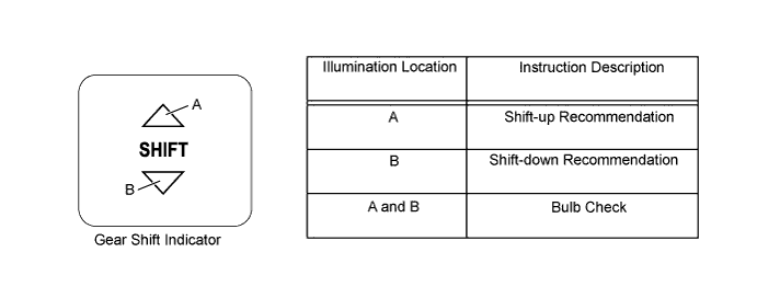
Upon receiving a shift instruction request from the ECM, the meter ECU will illuminate the indicator light.
-
The 2 indicator lights illuminate simultaneously during a bulb check.
-
-
-
CONSTRUCTION
-
Gear Layout
-
The No. 1 and No. 2 output shafts are placed on the circumference of the differential ring gear.
-
The reverse idler gear is engaged with the 1st and reverse drive gear of the input shaft and the reverse driven gear of the No. 2 output shaft.
-
The 1st, 2nd, 3rd, and 4th driven gears are located on the No. 1 output shaft.
-
The 5th, 6th, and reverse driven gears are located on the No. 2 output shaft.
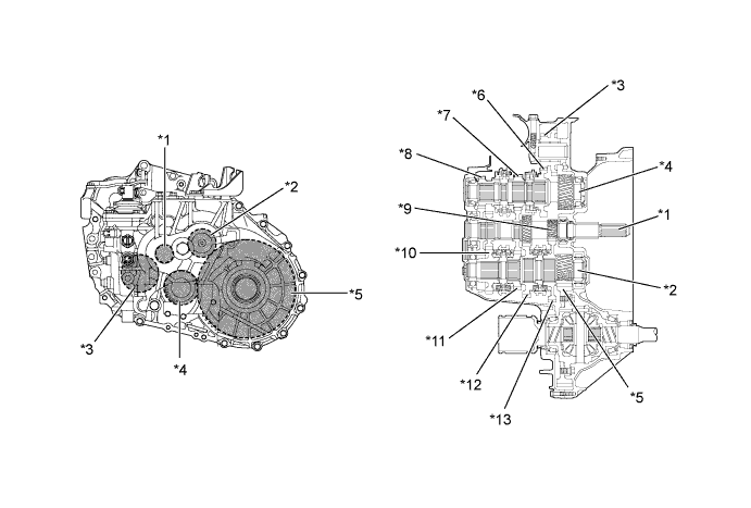
Text in Illustration *1 Input Shaft *2 No. 1 Output Shaft *3 Reverse Idler Gear *4 No. 2 Output Shaft *5 Differential Ring Gear *6 Reverse Driven Gear *7 5th Driven Gear *8 6th Driven Gear *9 1st and Reverse Drive Gear *10 3rd Driven Gear *11 4th Driven Gear *12 2nd Driven Gear *13 1st Driven Gear - - Synchromesh Mechanism Gear Synchromesh Mechanism Type 1st Triple-cone 2nd Triple-cone 3rd Triple-cone 4th Double-cone 5th Single-cone 6th Single-cone Reverse Single-cone
-
-
Shift and Select Mechanism
-
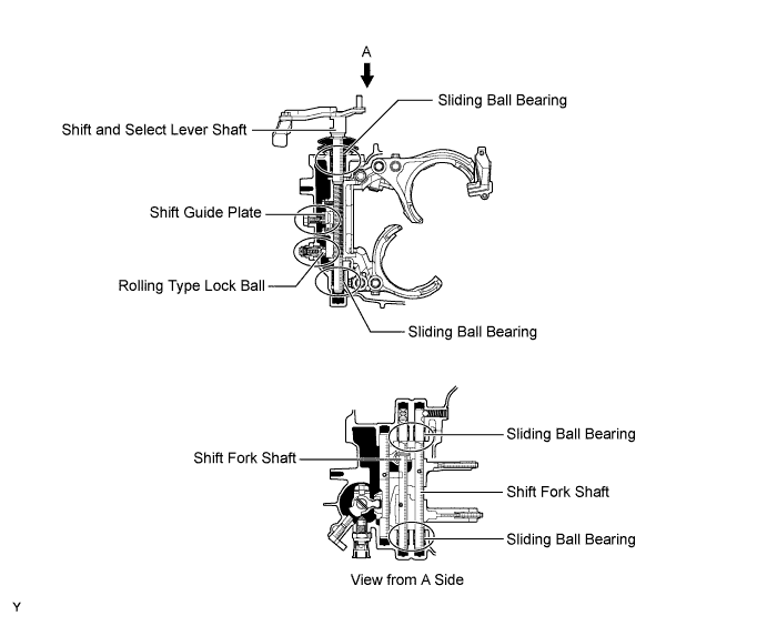
Sliding ball bearings are used in the shift and select lever shaft and shift fork shafts to improve the shift feeling.
-
A rolling type rock ball is used in the shift and select lever shaft to improve the shift feeling.
-
A shift gate plate is provided for the shift and select lever shaft to clarify the shift knob position and achieve accurate shift operation.
-
-
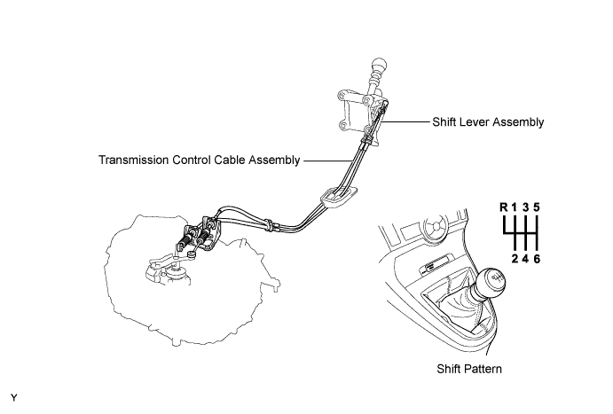
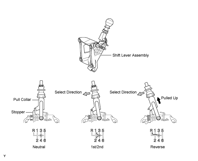
Shift Control Mechanism
-
A pull collar type shift lever assembly, which is equipped with an inhibit mechanism, is used.
-
The shift control mechanism consists of a shift lever assembly and a transmission control cable assembly.
-
A stopper cover is provided on the 1st/2nd side, so that the pull collar must be pulled upward in order to shift into reverse. This reduces the amount of shift effort and ensures a precise shifting operation.
-
-