INTAKE SYSTEM DETAILS
-
CONSTRUCTION
-
Diesel Throttle Body
-
A linkless-type diesel throttle body is used to achieve excellent throttle control.
-
A DC motor with excellent response and minimal power consumption is used for the throttle control motor. The ECM performs the duty ratio control of the direction and the amperage of the current that flows to the throttle control motor in order to regulate the opening angle of the throttle valve.
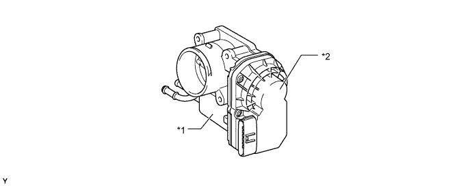
Text in Illustration *1 Throttle Control Motor *2 Throttle Position Sensor
-
-
Turbocharger Sub-assembly (Models with DPF Catalyst)
-
The variable nozzle vane type turbocharger consists primarily of a turbine, nozzle vane, unison ring, nozzle ring and turbocharger variable nozzle motor (DC motor and nozzle vane position sensor).
-
This turbocharger has achieved improvements in low-speed torque, fuel consumption and emission reduction. Both torque improvement at low speed and low fuel consumption are achieved by using a small size turbocharger because it enables high boost pressure at low speed. Response in boost pressure change is improved by changing control from the actuator to DC motor.
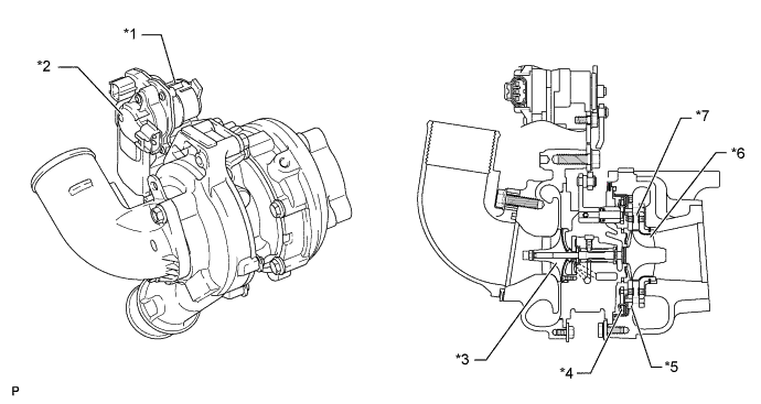
Text in Illustration *1 DC Motor *2 Nozzle Vane Position Sensor *3 Impeller Wheel *4 VGS Link Plate *5 Nozzle Ring *6 Turbine Wheel *7 Nozzle Vane - -
-
-
Turbocharger Sub-assembly (Models without DPF Catalyst)
-
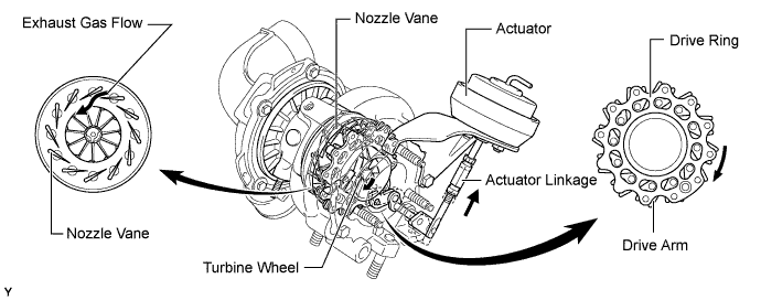
The variable nozzle vane type turbocharger sub-assembly consists primarily of a turbine, nozzle vane, unison ring and actuator.
-
The variable nozzle vane type turbocharger sub-assembly drives the vacuum type actuator in accordance with engine condition, and controls the nozzle vane in order to achieve high engine output, low fuel consumption and low emissions.
-
The turbocharger sub-assembly is cooled by the engine oil.
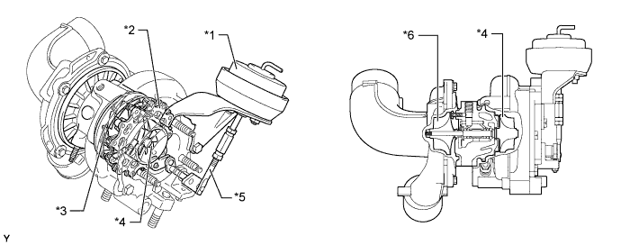
Text in Illustration *1 Actuator *2 Drive Ring *3 Nozzle Vane *4 Turbine Wheel *5 Actuator Linkage *6 Impeller Wheel -
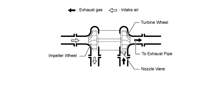
The exhaust gas from the exhaust manifold goes through the nozzle vane inside the turbocharger housing, and flows to the exhaust pipe through the turbine. The speed of the turbine (supercharging pressure) differs depending on the flow velocity of the exhaust gas going through the turbine. The flow velocity of the exhaust gas is controlled by the nozzle vane opening.
-
-
-
OPERATION
-
Turbocharger Sub-assembly (Models with DPF Catalyst)
-
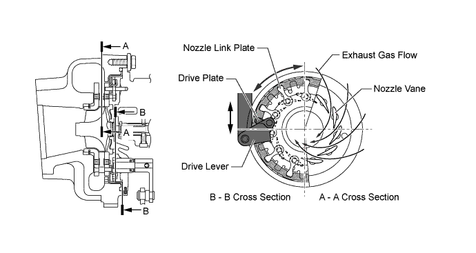
At Low Load Range or Low Speed Range
-
The DC motor moves the drive lever in the closing direction of the nozzle vanes in accordance with signals from the ECM.
-
This results in increasing the velocity of the exhaust gas flowing to the turbine, as well as the speed of the turbine. As a result, torque is improved when the engine is running at low speeds.
-
-
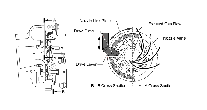
At High Load Range or High Speed Range
-
When the engine is running in high load range or a high speed range, the nozzle vanes are opened and the discharging pressure is maintained at a certain level.
-
-
-
Turbocharger Sub-assembly (Models without DPF Catalyst)
-
At Low Load Range or Low Speed Range
-
When the engine is running in a low load range or a low speed range, the actuator pulls up the actuator linkage. The actuator linkage is connected to the unison ring. At the same time, the drive arms installed in the unison ring move to change the nozzle vane angle in the closing direction. As a result, the exhaust gas travels to the turbine at a faster speed, and engine torque is improved.
-
-
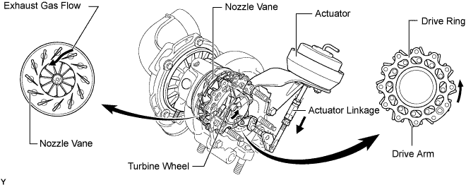
At High Load Range or High Speed Range
-
When the engine is running in a high load range or a high speed range, the actuator pulls down the actuator linkage. With this, the drive arm moves and this opens the nozzle vane and holds the specified supercharging pressure. Thus, exhaust gas back pressure is lowered, and output and fuel consumption are improved.
-
-
-