EMISSION CONTROL SYSTEM DETAILS
-
FUNCTION OF MAIN COMPONENTS
-
The main components of the exhaust emission control system are as follows:
Component Quantity Function ECM 1 The ECM controls the fuel injection timing, fuel injection volume and Exhaust Gas Recirculation (EGR) gas flow volume to reduce the exhaust gas emissions in accordance with the signals from the air fuel ratio sensor. Controls the air fuel ratio sensor heater. NOx Storage Reduction (NSR) Catalyst 1 Stores the NOx. Diesel Particulate Filter (DPF) Catalyst 1 Captures the Particulate Matter (PM). H2S Oxidation Catalyst 1 Reduces the H2S in the exhaust gas. Air Fuel Ratio Sensor 2 Detects the oxygen concentration in the exhaust gas.
For details, see the 1WW Engine Control section.
-
The main components of the Exhaust Gas Recirculation (EGR) system are as follows:
Component Quantity Function ECM 1 Based on the signals received from the sensors, the ECM determines the EGR volume in accordance with the engine operating conditions. EGR Temperature Sensor 1 Detects the EGR gas temperature. Exhaust Manifold Pressure Sensor 1 Detects the exhaust gas pressure in the exhaust manifold. EGR Valve Assembly EGR Valve 1 Actuated by the ECM, this valve controls the flow rate of EGR gas. EGR Valve Position Sensor 1 Detects the EGR valve position. EGR Cooler Assembly EGR Cooler 1 Cools EGR gas. EGR Cooler Bypass Switching Valve 1 Actuated by the ECM via the EGR bypass valve switching valve, this valve switches the flow passage of EGR gas in 2 stages. -
The main components of the catalyst regeneration control are as follows:
Component Quantity Function ECM 1 Based on the signals received from the sensors, the ECM determines the injection volume, injection timing and diesel throttle valve opening angle. Differential Pressure Sensor Assembly 1 Monitors the differential pressure before and after the DPF catalyst to detect whether the DPF catalyst is clogged. Exhaust Gas Temperature Sensor 2 Detects the temperature of the exhaust gas. Air Fuel Ratio Sensor 2 Detects the oxygen concentration in the exhaust gas.
For details, see the 1WW Engine Control section.
Injector Assembly 4 Injects the fuel to the cylinder.
For details, see the 1WW Fuel section.
Diesel Throttle Body Assembly
-
Diesel Throttle Valve
-
Throttle Control Motor
1 Actuated by the ECM, the diesel throttle valve controls the flow rate of intake air.
For details, see the 1WW Engine Control section and 1WW Intake / Exhaust section.
-
-
The main components of the blow-by gas ventilation system are as follows:
Component Quantity Function Pressure Control Valve 1 Maintains a constant vacuum in the cylinder block sub-assembly.
For details, see the 1WW Engine Mechanical section.
Oil Separator 1 Collects oil mist in the blow-by gas, reducing the oil consumption.
For details, see the 1WW Engine Mechanical section.
-
-
SYSTEM CONTROL
-
Air Fuel Ratio Sensor Heater Control
-
The ECM controls the air fuel ratio sensor heater according to the engine condition in order to promote the warm-up of the air fuel ratio sensor.
-
-
Exhaust Gas Recirculation (EGR) System
-
Based on the signals received from the sensors, the ECM determines the EGR volume via the EGR valve and EGR cooler bypass switching valve in accordance with the engine condition.
-
-
Catalyst Regeneration Control
-
The ECM judges the NSR catalyst condition based on the fuel injection volume, intake air mass, and exhaust gas temperature to control the injector assemblies for NSR catalyst regeneration control.
-
The ECM judges the DPF catalyst condition based on signals from the exhaust gas temperature sensor, differential pressure sensor assembly and air fuel ratio sensor to control the throttle control motor and injector assemblies for DPF catalyst regeneration control.
-
-
Blow-by Gas Ventilation System
-
The amount of airflow through the cylinder block sub-assembly (blow-by gas introduction volume) is controlled in accordance with the engine operating conditions.
-
-
-
FUNCTION
-
Air Fuel Ratio Sensor Heater Control
-
Maintains the temperature of the air fuel ratio sensor at an appropriate level to increase detection accuracy of the oxygen concentration in exhaust gas.
-
-
Exhaust Gas Recirculation (EGR) System
-
This system is designed to help reduce and control NOx formation due to a peak temperature reduction in the engine combustion chamber, which is accomplished by the introduction of amounts of inert gas into the intake manifold.
-
-
Catalyst Regeneration Control
-
NSR catalyst regeneration control optimally regulates the fuel injection volume and fuel injection timing in order to reduce the NOx stored in the NSR catalyst.
-
DPF catalyst regeneration control optimally regulates the fuel injection volume, fuel injection timing and opening of the diesel throttle valve in order to burn Particulate Matter (PM) captured in the DPF catalyst.
-
-
Blow-by Gas Ventilation System
-
By introducing blow-by gas that has a large amount of HC into the intake manifold for combustion, the system prevents the blow-by gas from being discharged into the atmosphere.
-
-
-
CONSTRUCTION
-
EGR Valve Assembly
-
A water-cooled and electrically controlled type EGR valve assembly is used.
-
An EGR valve position sensor is provided in the EGR valve assembly in order to directly measure the actual valve opening amount. This measurement is then input into the ECM in order to improve the precision of the EGR system.
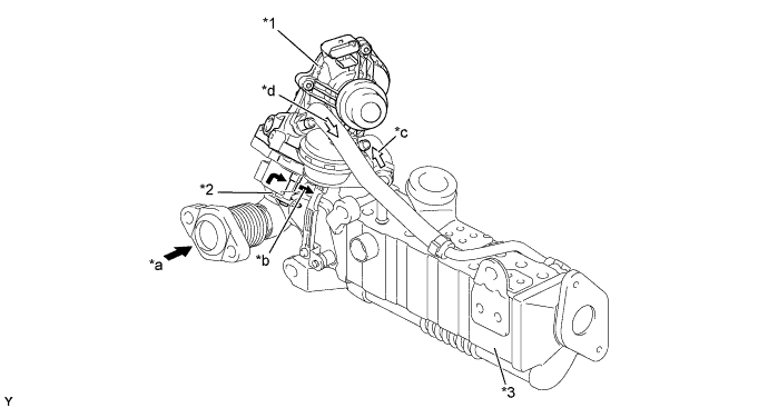
Text in Illustration *1 EGR Valve Assembly
-
EGR Valve Position Sensor
*2 EGR Valve *3 EGR Cooler Assembly - - *a Exhaust Gas (from Exhaust Manifold) *b Exhaust Gas (to EGR Cooler) *c Engine Coolant (In) *d Engine Coolant (Out) -
-
-
EGR Cooler Assembly
-
A water-cooled type EGR cooler is used in the EGR cooler assembly between the EGR valve assembly and intake manifold. In the water-cooled type EGR cooler, engine coolant flows through the exhaust gas passage to cool down the exhaust gas.
-
An EGR cooler bypass switching valve is used in the EGR cooler assembly. If exhaust gas is cooled down in the EGR cooler with a light engine load and low engine coolant temperature, the compression air temperature decreases. To prevent this, the exhaust gas passage is switched by the EGR cooler bypass switching valve.
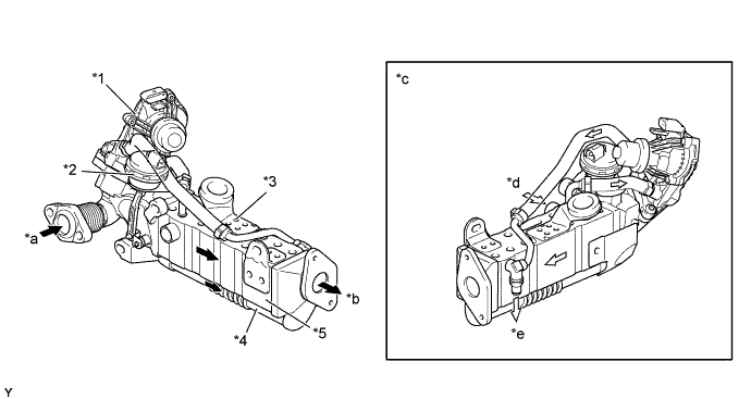
Text in Illustration *1 EGR Valve Assembly *2 Actuator (for EGR Cooler Bypass Switching Valve) *3 EGR Cooler Assembly
-
EGR Cooler Bypass Switching Valve
*4 Bypass Passage *5 EGR Cooler - - *a Exhaust Gas (from Exhaust Manifold) *b Exhaust Gas (to Intake Manifold) *c Engine Coolant Flow *d Engine Coolant Inlet *e Engine Coolant Outlet - - -
-
-
EGR Temperature Sensor
-
The EGR temperature sensor is installed at the end of the EGR cooler assembly. This sensor detects the EGR gas temperature.
Text in Illustration *1 Intake Manifold *2 EGR Temperature Sensor *3 EGR Cooler Assembly - -
-
-
Exhaust Manifold Pressure Sensor
-
The exhaust manifold pressure sensor is connected to the exhaust manifold. This sensor detects the exhaust gas pressure in the exhaust manifold.
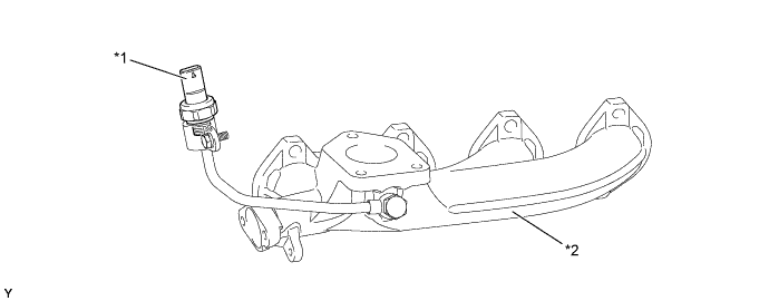
Text in Illustration *1 Exhaust Manifold Pressure Sensor *2 Exhaust Manifold
-
-
Differential Pressure Sensor Assembly
-
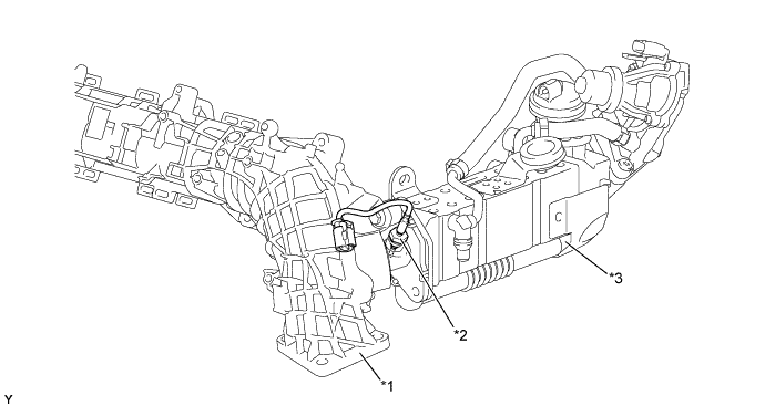
The differential pressure sensor measures the difference in pressure before and after the DPF catalyst in order to detect clogging.
-
The DPF catalyst and the sensor are connected with pipes and hoses.
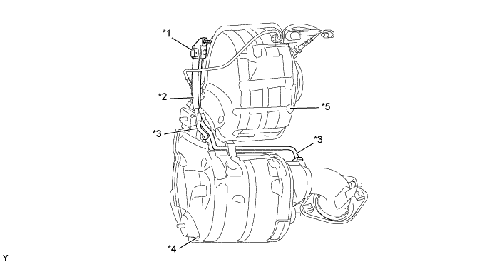
Text in Illustration *1 Differential Pressure Sensor Assembly *2 Hose *3 Pipe *4 DPF Catalyst *5 NSR Catalyst - -
-
-
Exhaust Gas Temperature Sensor
-
Thermistor type exhaust gas temperature sensors are used. The exhaust gas temperature sensor is installed before and after the NOx Storage Reduction (NSR) catalyst in order to detect the temperature of the exhaust gas.
Text in Illustration *1 Exhaust Gas Temperature Sensor (before NSR Catalyst) *2 Diesel Particulate Filter (DPF) Catalyst *3 Exhaust Gas Temperature Sensor (after NSR Catalyst) *4 NOx Storage Reduction (NSR) Catalyst
-
-
NOx Storage Reduction (NSR) Catalyst
-
A NSR catalyst is used to store the NOx.
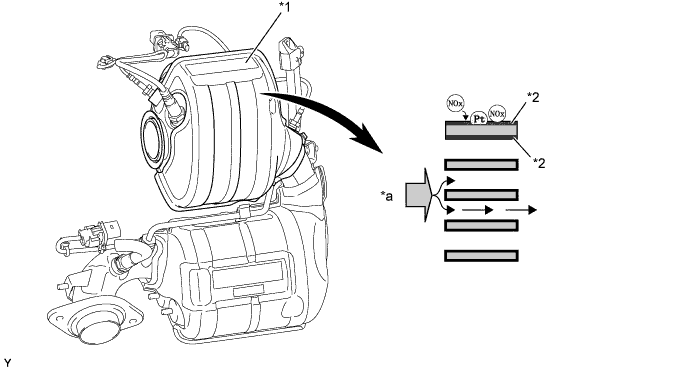
Text in Illustration *1 NOx Storage Reduction (NSR) Catalyst *2 NOx Storage Layer *a Exhaust Gas - -
-
-
Diesel Particulate Filter (DPF) Catalyst
-
A DPF catalyst is used to capture the PM.
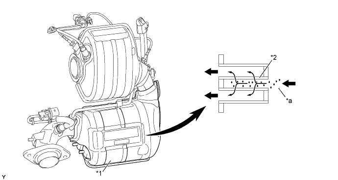
Text in Illustration *1 DPF Catalyst *2 Filter *a PM - - 
Exhaust Gas - -
-
-
H2S Oxidation Catalyst
-
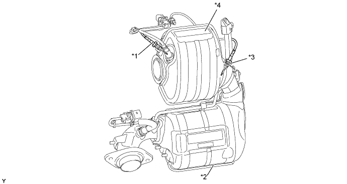
The H2S oxidation catalyst is used to reduce H2S in the exhaust gas.
-
The H2S oxidation catalyst has been placed in the main muffler to achieve a compact package and ensure the proper capacity of the main muffler.
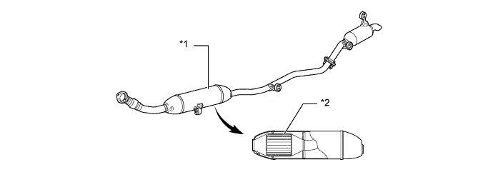
Text in Illustration *1 Main Muffler *2 H2S Oxidation Catalyst
-
-
-
OPERATION
-
Exhaust Gas Recirculation (EGR) System
-
By sensing the engine driving conditions and actual EGR valve opening amount, the ECM electrically operates the EGR valve assembly. As a result, the amount of recirculating exhaust gas is regulated.
-
The ECM switches the bypass passage of the EGR cooler assembly via the EGR bypass valve switching valve in order to optimize the temperature of the EGR gas and clean exhaust gases.
-
-
Catalyst Regeneration Control
-
The ECM calculates the amount of NOx in the NSR catalyst based on fuel injection volume, intake air mass and exhaust gas temperature, and operates the injectors for NOx reduction control.
-
As a result of the operation of these injectors, the air fuel ratio in the exhaust gas becomes rich to purify the NOx.
-
The ECM judges the DPF catalyst condition based on signals from various sensors. When the ECM determines that PM has accumulated in the DPF catalyst, the ECM activates regeneration control.
-
To reduce PM, the ECM controls the injection timing and the injection frequency of the injectors. In addition, the ECM controls the opening of the diesel throttle valve to maintain the exhaust gas temperature required to burn PM.
-
At the same time, the filter substrate temperature becomes high and PM reacts with active oxygen and changes into CO2for purification.
-
-
Blow-by Gas Ventilation System
-
The generated blow-by gas is separated from the engine oil using the oil separator and flows to the pressure control valve. The blow-by gas is drawn into the intake pipe from the pressure control valve and burned in each cylinder. For details of the oil separator and pressure control valve, see the 1WW Engine Mechanical section.
-
-