EMISSION CONTROL SYSTEM SYSTEM DIAGRAM
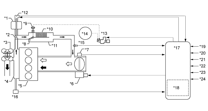
| *1 | EGR Valve Assembly | *2 | EGR Valve |
| *3 | Turbocharger Sub-assembly | *4 | Exhaust Manifold |
| *5 | Engine | *6 | Throttle Control Motor |
| *7 | Throttle Position Sensor | *8 | EGR Cooler Bypass Switching Valve |
| *9 | Actuator for EGR Cooler Bypass Switching Valve | *10 | EGR Cooler |
| *11 | EGR Cooler Assembly | *12 | EGR Valve Position Sensor |
| *13 | EGR Bypass Valve Switching Valve | *14 | Vacuum Pump |
| *15 | EGR Temperature Sensor | *16 | Exhaust Manifold Pressure Sensor |
| *17 | ECM | *18 | Atmospheric Pressure Sensor |
| *19 | Crankshaft Position Sensor | *20 | Accelerator Pedal Position Sensor |
| *21 | Engine Coolant Temperature Sensor | *22 | Turbo Pressure Sensor Assembly |
| *23 | Intake Air Temperature Sensor | *24 | Intake Mass Air Flow Meter Sub-assembly |
 |
Exhaust Gas |  |
Intake Air |
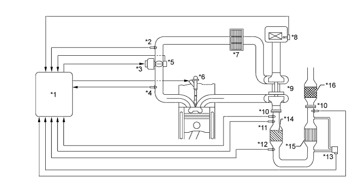
| *1 | ECM | *2 | Intake Air Temperature Sensor |
| *3 | Throttle Control Motor | *4 | Turbo Pressure Sensor Assembly |
| *5 | Throttle Position Sensor | *6 | Injector Assembly |
| *7 | Intercooler Assembly | *8 | Intake Mass Air Flow Meter Sub-assembly |
| *9 | Turbocharger Sub-assembly | *10 | Air Fuel Ratio Sensor |
| *11 | Exhaust Gas Temperature Sensor (before NSR Catalyst) | *12 | Exhaust Gas Temperature Sensor (after NSR Catalyst) |
| *13 | Differential Pressure Sensor Assembly | *14 | NSR Catalyst |
| *15 | DPF Catalyst | *16 | H2S Oxidation Catalyst |
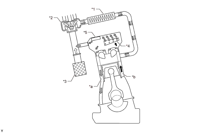
| *1 | Intercooler Assembly | *2 | Turbocharger Sub-assembly |
| *3 | Air Cleaner Assembly | *4 | Spring Tab Oil Separator |
| *5 | Pressure Control Valve | - | - |
| *a | Engine Oil Return Passage | *b | Blow-by Gas Passage |
| |
Blow-by Gas Mixed with Engine Oil | |
Intake Air |
 |
Blow-by Gas Separated from Engine Oil |  |
Engine Oil |