EMISSION CONTROL SYSTEM DETAILS
-
FUNCTION OF MAIN COMPONENTS
-
The main components of the 1AD-FTV engine emission control system are as follows:
Component Outline Quantity Function ECM 32-bit CPU 1 Effects overall control of the emission control system to suit the operating conditions of the engine in accordance with the signals provided by the sensors. EGR Valve DC Motor Type 1 Actuated by the ECM and controls the flow rate of EGR gas. EGR Cooler Water-cooled Type 1 Cools EGR gas. Exhaust Fuel Addition Injector Assembly* Solenoid Type 1 Injects fuel into the exhaust port. Differential Pressure Sensor Assembly* Semiconductor Strain Gauge Type 1 Monitors the differential pressure before and after the DPF catalyst to detect whether the DPF catalyst is clogged. Exhaust Gas Temperature Sensors* Thermistor Type 3 Located before and after the DPF catalyst and detect the temperature of the DPF catalyst. Air Fuel Ratio Sensor* Heated Type (Planar Type) 1 Detects the oxygen concentration in the exhaust gas.
-
*: Models with DPF catalyst
-
-
-
SYSTEM CONTROL
-
The emission control system of the 1AD-FTV engine has the following systems:
System Outline Catalyst Support Control* Based on the signals received from the sensors, the ECM controls the exhaust fuel addition injector to purify the Particulate Matter (PM). Air Fuel Ratio Sensor Heater Control* Maintains the temperature of the air fuel ratio sensor at an appropriate level to increase accuracy of detection of the oxygen concentration in exhaust gas. EGR Control Based on the signals received from the sensors, the ECM determines the EGR volume via the EGR valve and EGR cooler bypass valve in accordance with the engine condition.
-
*: Models with DPF catalyst
-
-
-
FUNCTION
-
Catalyst Support Control (Models with DPF Catalyst)
-
The ECM judges the exhaust manifold converter condition based on signals from the intake mass air flow meter sub-assembly, engine coolant temperature sensor, 3 exhaust gas temperature sensors, differential pressure sensor assembly and air fuel ratio sensor to control the injectors and exhaust fuel addition injector assembly for catalyst support control.
-
-
EGR Control
-
This system is designed to help reduce and control NOx formation due to a reduction of peak temperature in the engine combustion chamber, which is accomplished by the introduction of amount of inert gas into the intake manifold.
-
-
-
CONSTRUCTION
-
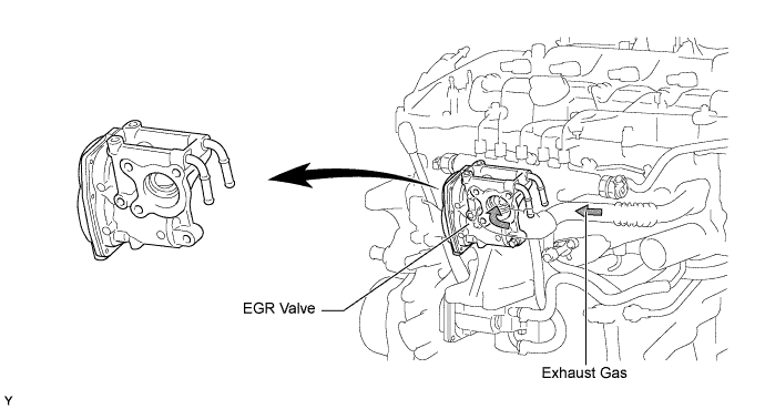
EGR Valve
-
A DC motor type of EGR valve is used. The placement of the EGR valve in the intake passage facilitates the uniform distribution of EGR gas and intake air.
-
An EGR valve position sensor is provided in the EGR valve. This sensor enables EGR valve control at a higher level of precision by detecting the opening angle of the EGR valve.
-
-
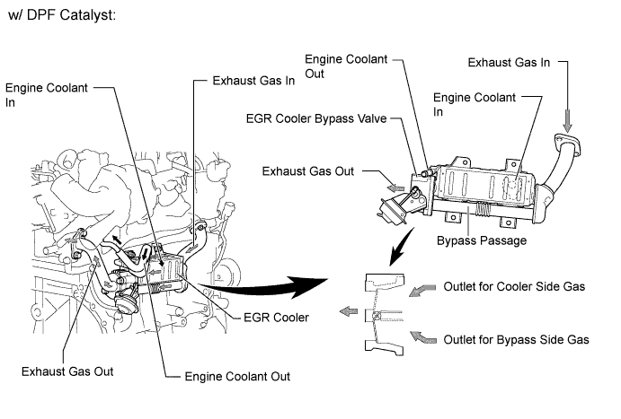
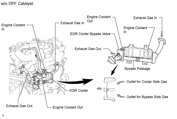
EGR Cooler
-
In the EGR cooler, engine coolant flows around the 7-layered gas passage in order to cool down.
-
An EGR cooler bypass with an EGR cooler bypass valve is used. When EGR gas is cooled down in the EGR cooler under a light engine load, the temperature of the compressed air in the cylinders decreases too much. To prevent this, the EGR gas passage is switched by the EGR cooler bypass valve.
-
-
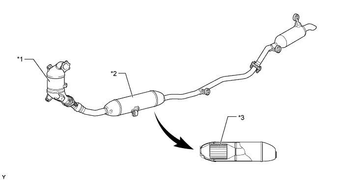
Exhaust Manifold Converter (Models with DPF Catalyst)
-
The exhaust manifold converter consists of an oxidation catalyst and a DPF catalyst.
-
The DPF catalyst purifies the PM, HC and CO.
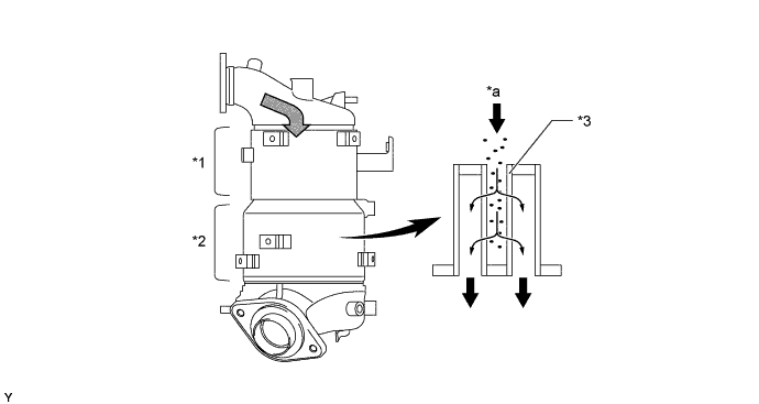
Text in Illustration *1 Oxidation Catalyst *2 DPF Catalyst *3 Filter - - *a Exhaust Gas - -
-
-
Oxidation Catalyst (Models without DPF Catalyst)
-
The oxidation catalysts are used.
-
The oxidation catalysts have been placed in the exhaust manifold converter and in the main muffler.
Text in Illustration *1 Exhaust Manifold Converter *2 Main Muffler *3 Oxidation Catalyst - -
-
-
Exhaust Fuel Addition Injector Assembly (Models with DPF Catalyst)
-
An exhaust fuel addition injector assembly is installed on the No. 4 exhaust port of the cylinder head. This injector supplies additional fuel into the No. 4 exhaust port and maintains the proper catalyst temperature for the purpose of PM recovery.
-
The exhaust fuel addition injector assembly consists of a needle valve body, a needle valve and a solenoid valve.

Text in Illustration *1 Solenoid Valve *2 Needle Valve *3 Needle Valve Body - -
-
-
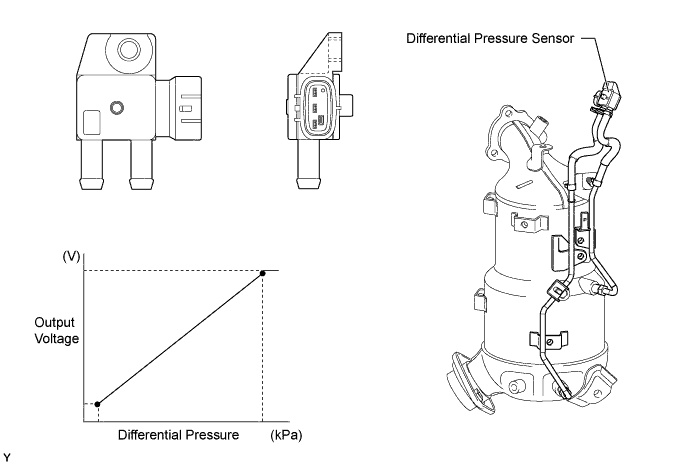
Differential Pressure Sensor Assembly (Models with DPF Catalyst)
-
The differential pressure sensor assembly measures the pressure differences between before and after the DPF catalyst with PM in order to detect clogging.
-
The sensor is mounted on the cowl, where the effects of vibration are minimal. The DPF catalyst and the sensor are connected with pipes and hoses.
-
-
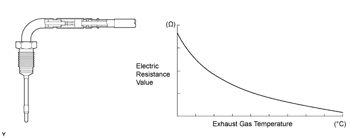
Exhaust Gas Temperature Sensor (Models with DPF Catalyst)
-
An exhaust gas temperature sensor, which is a thermistor type, is installed before and after the oxidation catalyst and after the DPF catalyst, in order to detect the temperature of the catalyst.
-
-
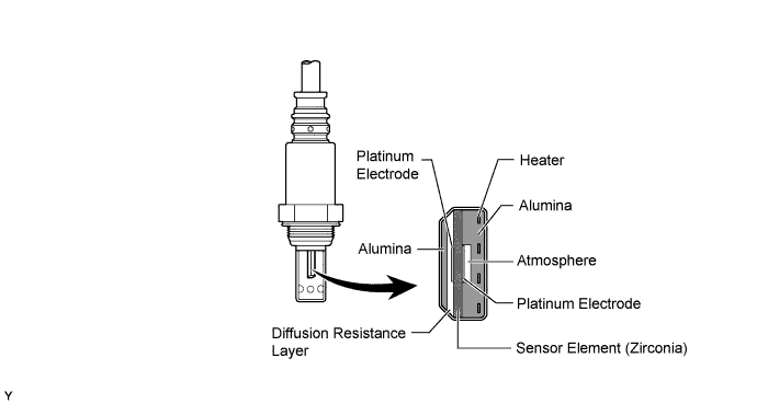
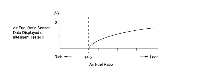
Air Fuel Ratio Sensor (Models with DPF Catalyst)
-
A planar type air fuel ratio sensor is used.
-
The planar type air fuel ratio sensor uses alumina, which excels in heat conductivity and insulation, to integrate the sensor element with the heater, thus improving the warm-up performance of the sensor.
-
This sensor is based on a sensor developed for gasoline engines. The cover has been changed for diesel engine application in order to eliminate the influences of the sensor temperature and the PM. This sensor, which is mounted after the DPF catalyst, detects the air fuel ratio after the gas has been reduced.
-
The air fuel ratio sensor data is approximately proportional to the existing air fuel ratio. The air fuel ratio sensor converts the oxygen density to the current and sends it to the ECM.
-
As a result, the detection precision of the air fuel ratio has been improved. The air fuel ratio sensor data can be read using an intelligent tester II.
-
-
-
OPERATION
-
Catalyst Support Control (Models with DPF Catalyst)
-
If the DPF catalyst temperature becomes low, catalyst performance decreases, resulting in an increase of the amount of PM stuck in the filter substrate. The ECM detects that the filter substrate is clogged by calculating the accumulated volume of the PM discharged by the engine. To reduce PM, the ECM controls the injection timing and the injection frequency of the injectors, and activates the exhaust fuel addition injector.
-
At the same time, the filter substrate temperature becomes high and PM reacts with active oxygen and changes into CO2for purification.
-
Fuel efficiency drops while this control is operative.
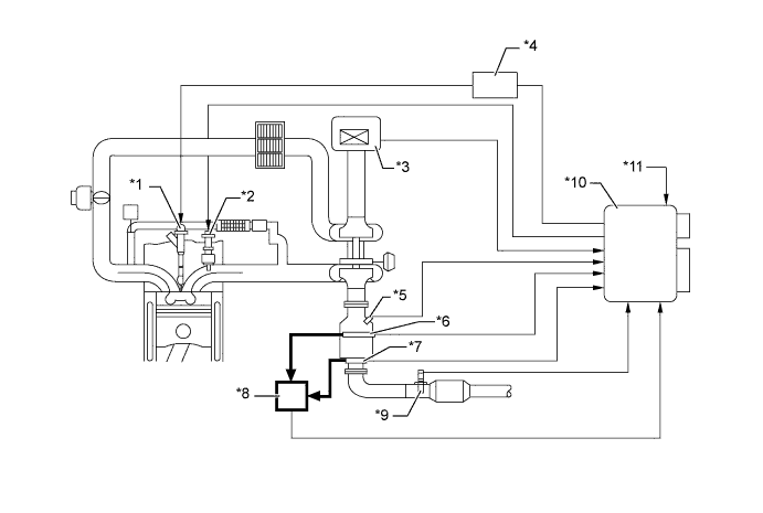
Text in Illustration *1 Injector Assembly *2 Exhaust Fuel Addition Injector Assembly *3 Intake Mass Air Flow Meter Sub-assembly *4 Injector Driver *5 Exhaust Gas Temperature Sensor *6 No. 2 Exhaust Gas Temperature Sensor (Upper Side) *7 No. 3 Exhaust Gas Temperature Sensor (Lower Side) *8 Differential Pressure Sensor Assembly *9 Air Fuel Ratio Sensor *10 ECM *11 Engine Coolant Temperature Sensor - - Tech Tips
-
When replacing the exhaust manifold converter with a new one, it is necessary to perform initialization of the DPF catalyst deterioration data history in the ECM by using an intelligent tester II.
-
When replacing the ECM with a new one, it is necessary to read DPF catalyst deterioration data history from the installed ECM and then transfer that data history to the new ECM by using an intelligent tester II. When the DPF catalyst deterioration data history is not transferred, Diagnostic Trouble Code (DTC) P062F is stored in the ECM and the MIL comes on.
-
When replacing both the exhaust manifold converter and the ECM, it is necessary to perform initialization of the DPF catalyst deterioration data history in the ECM using an intelligent tester II. When DPF catalyst deterioration history initialization is not performed, DTC P062F is stored in the ECM and the MIL comes on.
-
-
-
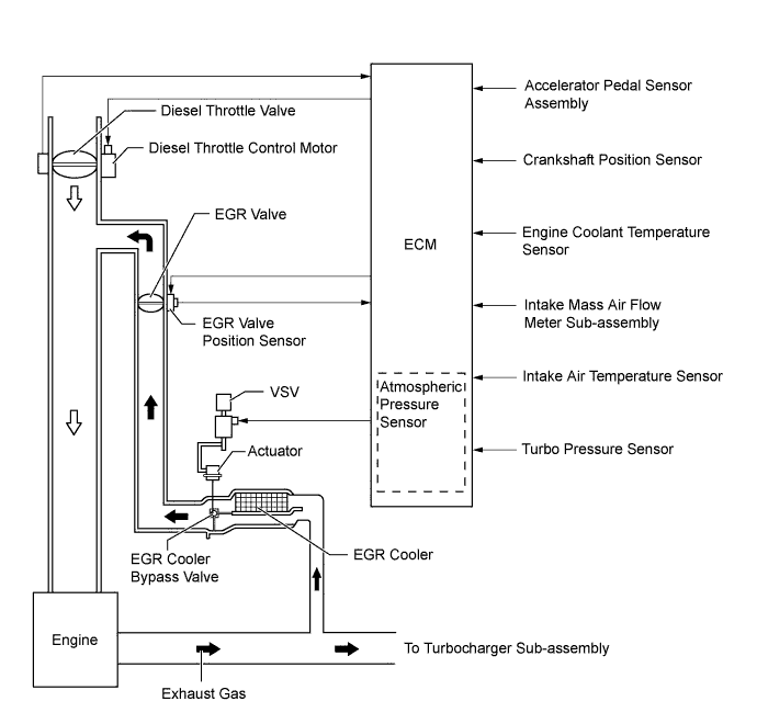
EGR Control
-
The ECM actuates the EGR valve, which regulates the volume of EGR gas recirculation, in accordance with the engine conditions.
-
The ECM controls the VSV for EGR cooler, which switches the bypass passage and cooler passage in the EGR cooler, in order to optimize the temperature of EGR gas.
-
-