FUEL SYSTEM DETAILS
-
CONSTRUCTION
-
Fuel Injector Assembly
-
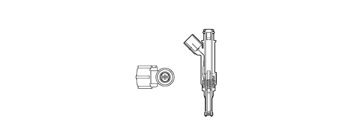
The fuel injector assembly is shaped to form a long nozzle. This shortens the distance from the fuel injector assembly to the intake valve, which prevents the fuel from adhering to the intake port walls and reduces HC exhaust emissions. Depending on the type of fuel that is used, a 12-hole type fuel injector assembly is provided.
-
-
Fuel Delivery Pipe Sub-assembly
-
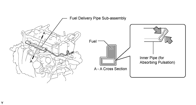
An inner pipe is provided inside the fuel delivery pipe to absorb fuel pulsations.
-
This eliminates the use of the pulsation damper provided on conventional models, making the fuel system more compact and lightweight. When the fuel pulsates, the shape of the inner pipe changes with the pulsation, thus changing the internal capacity of the delivery pipe. This change in capacity absorbs the fuel pulsations.
-
-
Fuel Tank
-
A multiplex layered plastic fuel tank is used. This fuel tank consists of 6 layers of 4 types of material.
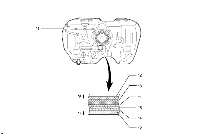
Text in Illustration *1 Fuel Tank *2 High Density Polyethylene (HDPE) *3 Regrind Material *4 Adhesive *5 Ethylene Vinyl Alcohol Copolymer (EVOH) *6 Fuel Tank Outside *7 Fuel Tank Inside - -
-
-
Fuel Suction with Pump and Gauge Tube Assembly
-
A compact fuel suction with pump and gauge tube assembly is used. Its basic components are a fuel pump, a fuel filter, a fuel pressure regulator assembly, a charcoal canister and a fuel sender gauge assembly.
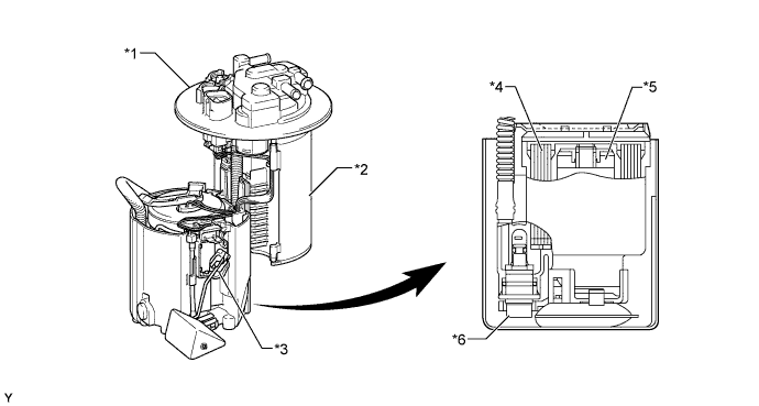
Text in Illustration *1 Suction with Pump and Gauge Tube Assembly *2 Charcoal Canister *3 Fuel Sender Gauge Assembly *4 Fuel Filter *5 Fuel Pump *6 Fuel Pressure Regulator Assembly
-
-