ECD SYSTEM DETAILS
-
FUNCTION OF MAIN COMPONENTS
-
The main components of the 1AD-FTV engine control system are as follows:
Component Outline Quantity Function ECM 32-bit CPU 1 The ECM effects overall control of the engine control system to suit the operating conditions of the engine in accordance with the signals provided by the sensors. Injector Driver Including Built-in DC/DC Converter 1 This injector driver is used to drive the injector at high speeds. The injector driver achieves high-speed driving under high fuel pressure conditions through the use of a DC/DC converter that provides a high voltage, quick-charging system. Turbo Pressure Sensor Semiconductor Silicon Chip Type 1 This sensor uses built-in semiconductors to detect the intake manifold pressure. Atmospheric Pressure Sensor Semiconductor Silicon Chip Type 1 This sensor, which is built into the ECM, uses semiconductors to detect the atmospheric pressure. Fuel Pressure Sensor Semiconductor Strain Gauge Type 1 This sensor uses built-in semiconductors to detect the internal pressure of the common-rail. Crankshaft Position Sensor [Rotor Teeth] Pick-up Coil Type [36 - 2] 1 This sensor detects the engine speed and performs the cylinder identification. Camshaft Position Sensor [Rotor Teeth] Magneto-Resistance Element (MRE) Type [3]*1 1 This sensor performs the cylinder identification. Pick-up Coil Type [1]*2 Intake Mass Air Flow Meter Sub-assembly Hot-wire Type 1 This sensor uses a built-in hot-wire to directly detect the intake air mass and flow rate. Intake Air Temperature Sensor Thermistor Type 1 This sensor, which is provided at the air cleaner outlet, detects the atmospheric temperature using an internal thermistor. This sensor is built into the intake mass air flow meter sub-assembly. Diesel Throttle Control Motor DC Motor 1 This diesel throttle control motor regulates the opening of the diesel throttle valve in accordance with the signals from the ECM. Engine Coolant Temperature Sensor Thermistor Type 1 This sensor detects the engine coolant temperature using an internal thermistor. Inlet Air Temperature Sensor Thermistor Type 1 This sensor detects the intake air temperature after the intercooler assembly.
-
*1: Models with DPF catalyst
-
*2: Models without DPF catalyst
-
-
-
SYSTEM CONTROL
-
The engine control system of the 1AD-FTV engine has the following systems:
System Outline Fuel Injection Volume Control Based on the signals received from the sensors, the ECM determines the fuel injection volume in accordance with the engine condition. Fuel Injection Timing Control Based on the signals received from the sensors, the ECM determines the fuel injection timing in accordance with the engine condition. Fuel Pressure Control Based on the signals received from the sensors, the ECM controls fuel pressure using the SCV in accordance with engine conditions. Pilot Injection Control Based on the signals received from the various sensors, the ECM determines pilot injection volume, timing, and the interval between pilot injection and main injection in accordance with the engine condition. Idle Speed Control The ECM determines the idle speed in accordance with the engine condition, and controls the fuel injection volume in order to maintain the target idle speed. Glow Plug Control
-
Controls the length of time that the current is applied to the glow plugs for, in accordance with engine coolant temperature.
-
Detects individual disconnections of circuit wires and short circuits by the use of the glow plug controller.*1
Turbo Pressure Control Based on the signals received from the sensors, the ECM controls the actuator via the DC motor*1 (E-VRV*2) in accordance with the engine condition. Cooling Fan Control Cooling fan operation is controlled by signals from the ECM based on the engine coolant temperature, air conditioning condition*3, engine speed and vehicle speed. iMT Control*1 Controls engine torque characteristics in accordance with the shift ranges and the depression amount of the accelerator pedal. Diesel Throttle Control Based on the signals received from the various sensors, the ECM determines throttle position in accordance with the engine condition and fully closes the diesel throttle control valve in order to reduce the vibration when the engine is stopped. Air Conditioning Cut-off Control*3 By switching the air conditioning compressor assembly on or off in accordance with the engine condition, driveability is maintained. Starter Control*4 Once the engine switch is pushed, this control continues to operate the starter until the engine is started. Engine Immobiliser Prohibits fuel injection if an attempt is made to start the engine with an invalid key. Oil Maintenance Management System When the ECM determines engine oil deterioration, "OIL MAINTENANCE REQUIRED" is shown on the multi-information display to inform the driver. Brake Override System The driving torque is restricted when the brake pedal is depressed while the accelerator pedal is depressed. (For the Activation Conditions and Inspection Method, refer to the Repair Manual.) Diagnosis When the ECM detects a malfunction, the ECM diagnoses and memorizes the failed section. Fail-safe When the ECM detects a malfunction, the ECM stops or controls the engine in accordance with the data already stored in the memory.
-
*1: Models with DPF catalyst
-
*2: Models without DPF catalyst
-
*3: Models with air conditioning system
-
*4: Models with entry and start system
-
-
-
FUNCTION
-
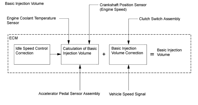
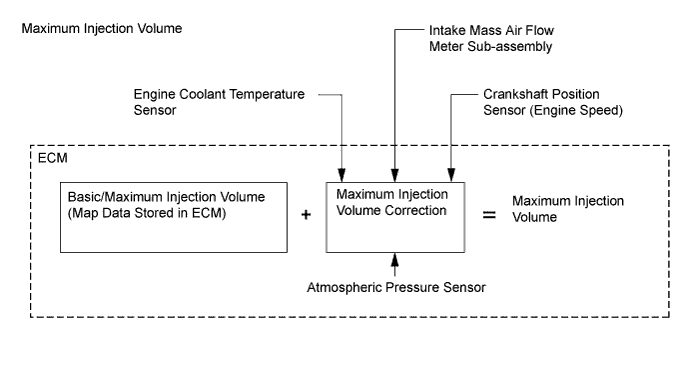
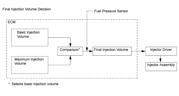
Fuel Injection Volume Control
-
The ECM compares the basic and maximum injection volumes, and determines the smaller calculated value to be the final injection volume. The ECM reduces injection volume to ensure driveability when the clutch switch assembly is on (the clutch pedal is depressed).
-
-
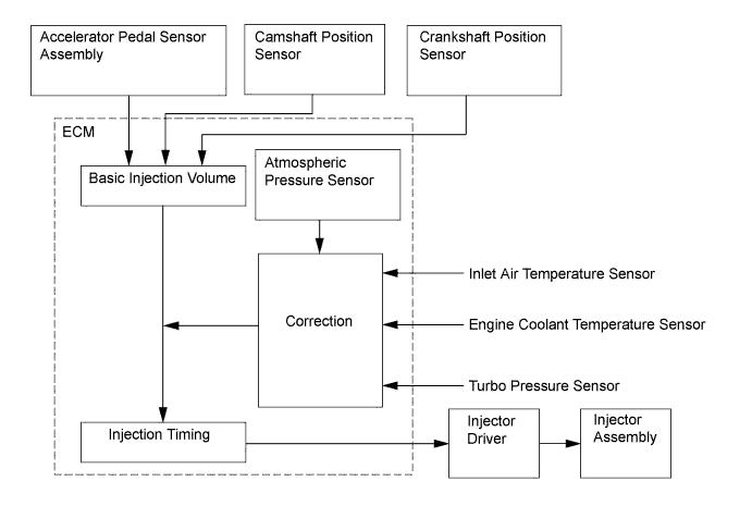
Fuel Injection Timing Control
-
Fuel injection timing is controlled as shown below:
-
-
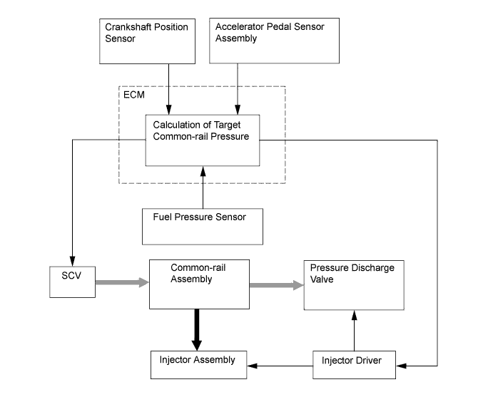
Fuel Pressure Control
-
The ECM calculates the target injection pressure (25 MPa to 200 MPa) based on the engine operating conditions, which include the signals from the accelerator pedal position sensor and the crankshaft position sensor. In order to control the fuel pressure, the SCV of the supply pump controls the pumping volume. Also, when the pressure is extremely high, when sudden deceleration occurs or when the engine is stopped, the pressure discharge valve installed on the common-rail controls the discharge volume. This ensures that the pressure detected by the fuel pressure sensor matches the target injection pressure.
-
-
iMT Control
-
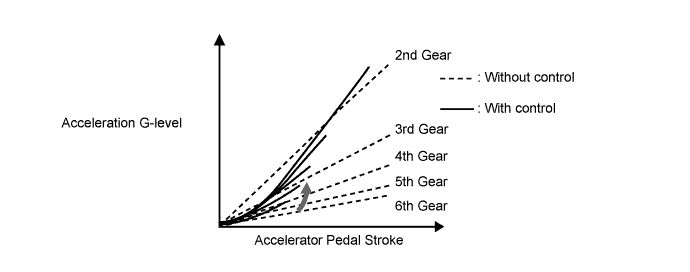
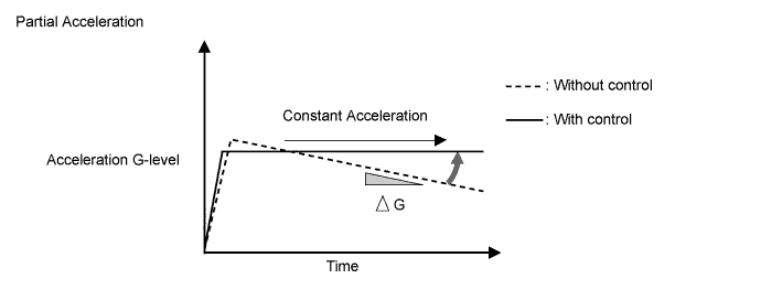
Acceleration Performance
-
To get more acceleration feeling and a constant acceleration feeling at higher shift ranges, the engine torque characteristic has been changed in each shift range.
-
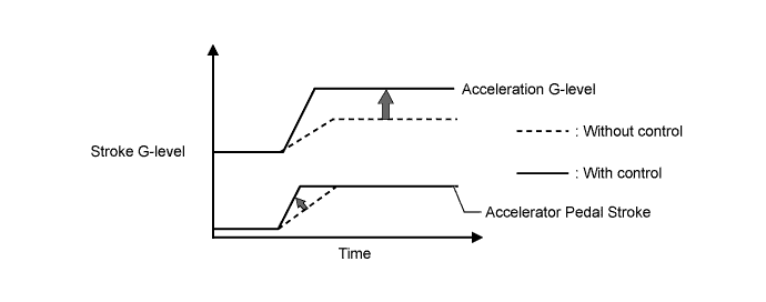
To get more acceleration feeling when the accelerator pedal is depressed quickly, the engine torque will be increased more than usual.
-
-
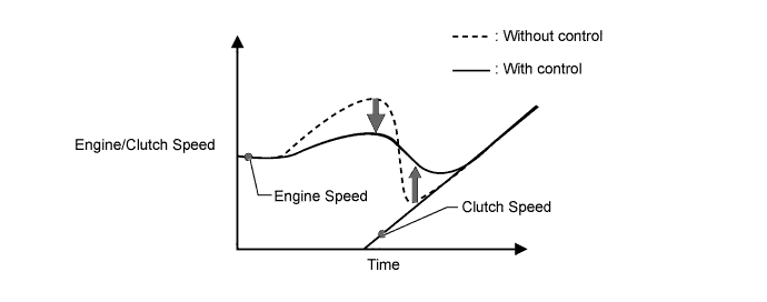
Starting-off Performance
-
To improve the engine speed controllability before the clutch engagement, the engine characteristic has been tuned suitably in accordance with the accelerator pedal depression amount at the time of vehicle starting.
-
To reduce an anxious feeling for engine stall during the clutch engagement operations, an engine torque characteristic to eliminate engine speed drop has been provided.
-
-
-
Cooling Fan Control
-
The cooling fan control system is controlled to achieve an optimal fan speed in accordance with the engine coolant temperature, vehicle speed, engine speed and air conditioning operating conditions*.
-
*: Models with air conditioning system
-
-
-
Starter Control (Models with Entry and Start System)
-
Depressing the clutch pedal and pressing the engine switch once will operate the starter continuously until the engine has started completely. Operability and starting operation have thereby been improved.
-
If the power management control ECU detects a start signal, it will monitor the engine speed signal (NE) from the ECM and operate the starter continuously until it determines that the engine has started completely.
-
-
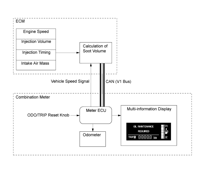
Oil Maintenance Management System
-
In this oil maintenance management system, the soot volume in the engine oil is calculated based on the engine operating conditions. Based on the calculated soot volume, the ECM transmits a signal to the combination meter that indicates that a reminder is necessary. This reminder informs the driver that it is necessary to change the engine oil.
Tech Tips
-
Since this system is controlled based on engine operating conditions, the "OIL MAINTENANCE REQUIRED" message may be displayed on the multi-information display before driving 30000 km (the maximum travel distance after oil maintenance). If the "OIL MAINTENANCE REQUIRED" message is displayed, the oil and oil filter should be replaced immediately.
-
This system does not determine the deterioration of the engine oil based on the elapsed time. Even if the "OIL MAINTENANCE REQUIRED" does not illuminate, the engine oil and oil filter should be changed at 2-year intervals at the maximum.
-
-
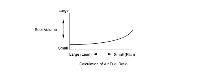
Soot Volume Calculation Method
-
The soot volume largely depends on the injection ending timing and the air fuel ratio. The ECM calculates soot volume from this information as shown in the graph below:
Tech Tips
For instructions on resetting the accumulated soot volume stored in the ECM, refer to the corresponding Repair Manual for this model.
-
-
-
-
CONSTRUCTION
-
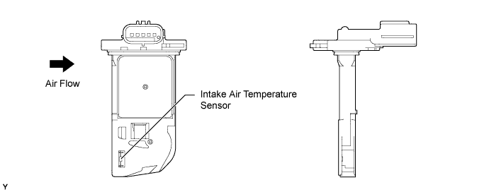
Intake Mass Air Flow Meter Sub-assembly
-
This intake mass air flow meter sub-assembly, which is a slot-in type, allows passage of the intake air through the detection area. By directly measuring the mass and the flow rate of the intake air, detection precision is improved and intake air resistance is reduced.
-
This intake mass air flow meter sub-assembly has a built-in intake air temperature sensor.
-
-
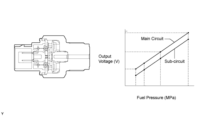
Fuel Pressure Sensor
-
The fuel pressure sensor outputs a signal to the ECM that represents the fuel pressure in the common-rail assembly in order to allow the ECM to constantly regulate the fuel at an optimal pressure.
-
The fuel pressure sensor contains 2 circuits (main and sub), which enable the ECM to constantly compare the values detected by the 2 circuits. As a result of this comparison, the ECM can determine that a fault exists, allowing fail-safe control to occur.
-
-
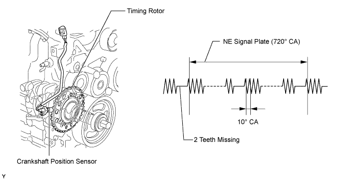
Crankshaft Position Sensor
-
The timing rotor of the crankshaft consists of 34 teeth with 2 teeth missing. The crankshaft position sensor outputs the crankshaft rotation signals every 10°, and the missing teeth are used to determine the top dead center.
-
-
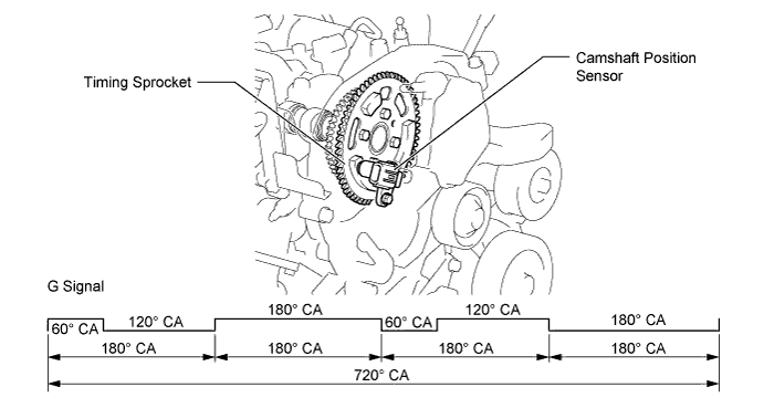
Camshaft Position Sensor (Models with DPF Catalyst)
-
Magneto-Resistance Element (MRE) type camshaft position sensor is used. To detect each camshaft position, a timing rotor that is part of the camshaft is used to generate 3 (3 high output, 3 low output) pulses for every 2 revolutions of the crankshaft.
-
The MRE type sensor consists of an MRE, a magnet and a sensor.
-
The direction of the magnetic field changes due to the profile (protruding and non-protruding portions) of the timing rotor, which passes by the sensor. As a result, the resistance of the MRE changes and the output voltage to the ECM changes to high or low. The ECM detects the crankshaft and camshaft positions based on this output voltage.
-
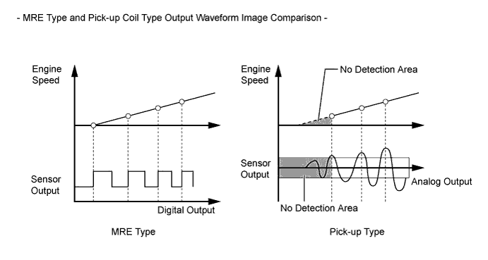
The differences between the MRE type sensor and the pick-up coil type sensor used on the conventional models are as follows:
-
The MRE type sensor outputs a constant level of high and low digital signals regardless of the engine speed. Therefore, the MRE type sensor can detect the positions of the crankshaft and camshaft at an early stage of cranking.
-
The pick-up coil type sensor outputs analog signals with levels that change with the engine speed.
-
-
-
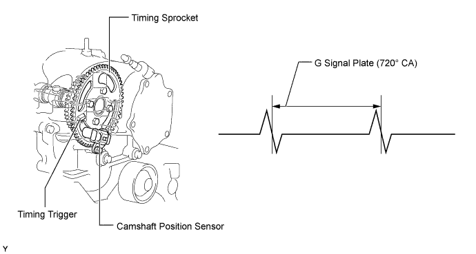
Camshaft Position Sensor (Models without DPF Catalyst)
-
A pick-up coil type camshaft position sensor is used to detect the camshaft position. The sensor generates 1 signal in every 2 revolutions of the crankshaft by using the timing trigger of the timing sprocket.
-
-
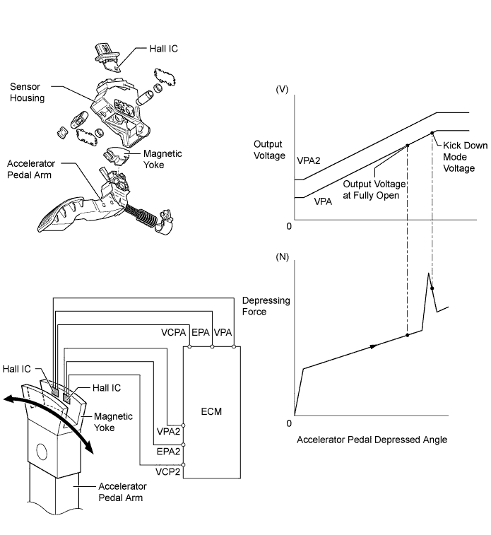
Accelerator Pedal Sensor Assembly
-
The non-contact type accelerator pedal position sensor uses a Hall IC.
-
The magnetic yoke mounted at the base of the accelerator pedal arm moves around the Hall IC in accordance with the accelerator pedal position. The Hall IC converts the changes in the magnetic flux that occur at that time into electrical signals, and sends them to the ECM.
-
This accelerator pedal sensor assembly includes 2 Hall ICs and circuits for the main and sub signals. The accelerator pedal sensor assembly converts the accelerator pedal depressed angles into electric signals with 2 differing characteristics and outputs them to the ECM.
-
On models with cruise control system, when the depressing force applied to the accelerator pedal is greater than a predetermined amount, the ECM detects a "kick down mode" from the VPA signal sent from the accelerator pedal sensor assembly .
-
-
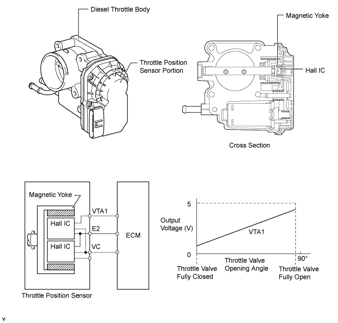
Throttle Position Sensor
-
A non-contact type throttle position sensor is mounted on the diesel throttle body, and it uses a Hall IC.
-
The Hall IC is surrounded by a magnetic yoke. The Hall IC converts the changes that occur in the magnetic flux into electrical signals, and outputs them in the form of throttle valve position signals to the ECM.
-
-
-
OPERATION
-
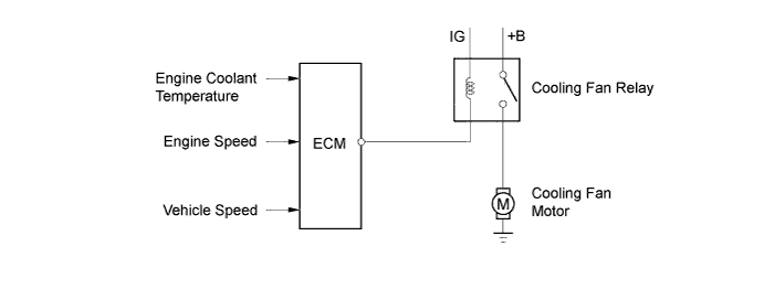
Cooling Fan Control
-
On models without air conditioning system, the ECM controls the operation of the cooling fan based on the engine coolant temperature, engine speed and vehicle speed.
-
On models with air conditioning system, the ECM activates the cooling fan relay to control the cooling fan in accordance with the engine coolant temperature, air conditioning condition, engine speed and vehicle speed.
-
The cooling fan speeds are controlled in 2 stages: low speed (series connection) and high speed (parallel connection).

-
-
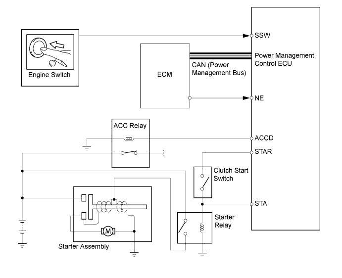
Starter Control (Models with Entry and Start System)
-
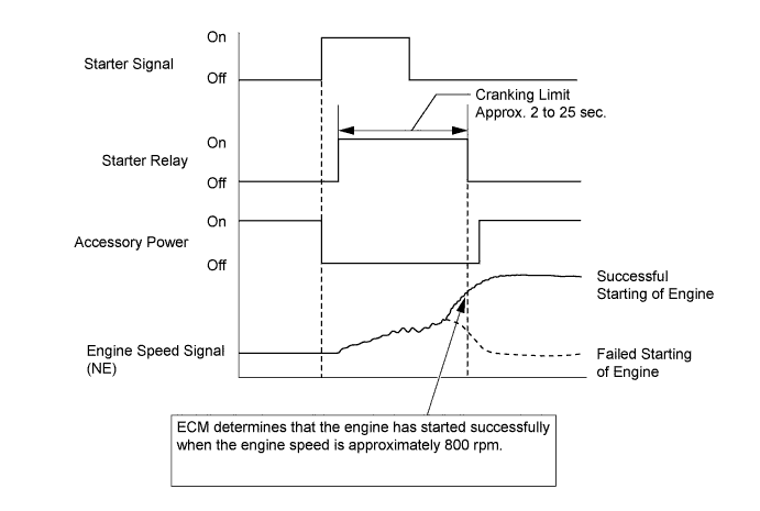
When the driver pushes the engine switch once and the power management control ECU detects a start signal, the power management control ECU will output the ACCD and STAR signals and begin cranking. Also, the driver can continue cranking for up to 30 seconds by pushing and holding the engine switch.
-
If the engine speed reaches approximately 800 rpm, the ECM will judge that the engine has started and will send a signal to the power management control ECU using CAN communication. The power management control ECU will then stop the operation of the starter.
-
If CAN communication is cut between the power management control ECU and the ECM, the power management control ECU will receive an engine speed signal (NE) directly from the ECM and will stop the operation of the starter.
-
This system will cut off the power current which activates the accessories while the engine is being cranked. This prevents the intermittent blinking of the accessory lights caused by the voltage instability that occurs during engine cranking.
-
This system has the following protections:
-
The starter will not operate if the engine is operating normally.
-
When the engine switch is pushed and held, cranking stops once the engine speed reaches a pre-determined level. This prevents the starter from over-revving.
-
When the engine does not start even after approximately 6 seconds of starter operation, the power management control ECU cancels the starter relay output. Furthermore, if the engine does not start after the engine switch has been pushed and held and cranking has continued for 30 seconds, cranking will be canceled in order to protect the starter.
-
It will not be possible to operate the starter for 2 seconds after engine starting has failed and cranking has been canceled. This helps to protect the starter.
-
-
-