LIGHTING SYSTEM DETAILS
-
FUNCTION OF MAIN COMPONENTS
-
Daytime Running Light System
Component Function Main Body ECU (Multiplex Network Body ECU) The main body ECU (multiplex network body ECU) receives various signals and illuminates the daytime running lights. Power Distributor (Engine Room Junction Block) DRL Relay The relay illuminates the daytime running lights. Instrument Panel Junction Block Assembly TAIL Relay The TAIL relay illuminates the taillights, front position lights and license plate lights. Power Management Control ECU The power management control ECU outputs a READY signal and transmits it to the main body ECU (multiplex network body ECU). Multi-information Switch (Steering Pad Switch Assembly) Menu Switch The menu switch is pressed and held to change the multi-information display to customization mode. ENTER Switch The ENTER switch enables or disables the operation of the daytime running lights. Radio Receiver Assembly*1 The radio receiver assembly*1 or multi-media module receiver assembly*2 enables or disables the operation of the daytime running lights. Multi-media Module Receiver Assembly*2 Headlight Dimmer Switch Light Control Switch The light control switch outputs a light control signal and transmits it to the main body ECU (multiplex network body ECU). *1: Models with Lexus Display Audio System
*2: Models with HDD Navigation System
-
High Intensity Discharge (HID) Headlight System
Component Function Headlight Dimmer Switch Assembly The headlight dimmer switch assembly transmits a HEAD position signal to the main body ECU (multiplex network body ECU). Main Body ECU (Multiplex Network Body ECU) The main body ECU (multiplex network body ECU) receives the HEAD position signal and transmits a signal to the power distributor (engine room junction block). Headlight Assembly Discharge Bulb The discharge bulb light shines ahead over a broader area and further forward, increasing the area visible to the driver. Light Control ECU The light control ECU transforms battery voltage to a high voltage of up to 30000 V and applies it to the discharge bulb in order to illuminate them. Combination Meter Assembly Taillight Indicator Light The taillight indicator light lights up to inform the driver when the taillights turn on. Power Distributor (Engine Room Junction Block) HEAD Relays The relays supply the power to the light control ECUs. -
Light Emitting Diode (LED) Headlight System
Component Function Headlight Dimmer Switch Assembly The headlight dimmer switch assembly transmits a HEAD position signal to the main body ECU (multiplex network body ECU). Main Body ECU (Multiplex Network Body ECU) The main body ECU (multiplex network body ECU) receives the HEAD position signal and transmits a signal to the light control ECU. Headlight Assembly Light Emitting Diode (LED) The Light Emitting Diode (LED) light shines ahead over a broader area and further forward, increasing the area visible to the driver. Light Control ECU The light control ECU keeps a constant level of direct current applied to the LED, achieving stable LED illumination. Combination Meter Assembly Taillight Indicator Light The taillight indicator light lights up to inform the driver when the taillights turn on. Master Warning Light The master warning light illuminates to inform the driver when the light control ECU detects malfunctions in this system Multi-information Display The multi-information display displays a warning message to inform the driver when the light control ECU detects a malfunction in this system. Power Distributor (Engine Room Junction Block) HEAD Relays The relays supply the power to the light control ECUs. -
Intelligent Adaptive Front-lighting System (AFS)
Component Function AFS ECU (Headlight Swivel ECU Assembly)
-
The AFS ECU (headlight swivel ECU assembly) receives various signals, calculates the target lighting angle, and actuates the headlight swivel actuator.
-
When the AFS ECU (headlight swivel ECU assembly) detects malfunctions, the AFS ECU flashes the AFS OFF indicator light.
Headlight Assembly (LH, RH) Headlight Swivel Motor (LH, RH) Driven by the AFS ECU (headlight swivel ECU assembly) the headlight swivel motor moves the low beam left or right to the angle calculated by the AFS ECU (headlight swivel ECU assembly). Steering Angle Sensor The steering angle sensor outputs the steering angle. Power Management Control ECU The power management control ECU performs the gateway function between the CAN No. 1 bus and CAN No. 2 bus. Main Body ECU (Multiplex Network Body ECU) The main body ECU (multiplex network body ECU) receives a HEAD position signal from the light control switch. Skid Control ECU
-
The skid control ECU transmits the signals of the front RH and LH speed sensors to the AFS ECU (headlight swivel ECU assembly).
-
The skid control ECU receives the zero point signal from the steering angle sensor and transmits it to the AFS ECU (headlight swivel ECU assembly).
Headlight Dimmer Switch Light Control Switch The light control switch transmits a HEAD position signal to the main body ECU (multiplex network body ECU). Combination Meter Assembly AFS OFF Indicator Light
-
The AFS OFF indicator light lights up when the AFS control is stopped by the multi-information switch (steering pad switch assembly).
-
The AFS OFF indicator light flashes when the AFS ECU (headlight swivel ECU assembly) detects a malfunction.
Master Warning Light The master warning light illuminates to inform the driver when the AFS ECU (headlight swivel ECU assembly) detects malfunctions in this system. Multi-information Display
-
The multi-information display changes to electronic features control mode to display the AFS on/off condition when the multi-information switch (steering pad switch assembly) is operated.
-
The multi-information display displays a warning message to inform the driver when the AFS ECU (headlight swivel ECU assembly) detects a malfunction in this system.
Multi-information Switch (Steering Pad Switch Assembly) Menu Switch The menu switch is pressed to change the multi-information display to electronic features control mode. ENTER Switch The ENTER switch can enable or disable the operation of the intelligent AFS. -
-
Automatic Headlight Beam Level Control System
Component Function Headlight Dimmer Switch Light Control Switch The light control switch transmits a HEAD position signal to the main body ECU (multiplex network body ECU). Main Body ECU (Multiplex Network Body ECU) The main body ECU (multiplex network body ECU) receives a HEAD position signal and transmits it to the AFS ECU (headlight swivel ECU assembly). AFS ECU (Headlight Swivel ECU Assembly)
-
The AFS ECU (headlight swivel ECU assembly) detects changes of vehicle movement based on the rear height control sensor, front RH wheel speed sensor and engine speed signals.
-
The AFS ECU (headlight swivel ECU assembly) outputs control signals to the headlight leveling motors based on the detected value.
-
This ECU provides initial set control and a fail-safe function.
Headlight Assembly Headlight Leveling Motor
-
Based on the signals received from the AFS ECU (headlight swivel ECU assembly), each headlight leveling motor moves the projector unit in the headlight to vary its angle.
-
The headlight leveling motor uses a stepper motor to precisely regulate the angle of the reflector.
Rear Height Control Sensor Sub-assembly RH*1 The rear height control sensor sub-assembly RH detects vehicle movement and transmits a signal to the AFS ECU (headlight swivel ECU assembly). Front Height Control Sensor Sub-assembly LH*2 The front height control sensor sub-assembly LH detects vehicle movement and transmits a signal to the suspension control ECU. Rear Height Control Sensor Sub-assembly LH*2 The rear height control sensor sub-assembly LH detects vehicle movement and transmits a signal to the suspension control ECU. Suspension Control ECU*2 The suspension control ECU transmits a vehicle movement signal to the AFS ECU (headlight swivel ECU assembly). Combination Meter Assembly AFS OFF Indicator Light*3 The AFS OFF indicator light flashes to inform the driver when the AFS ECU (headlight swivel ECU assembly) detects malfunctions in this system. Master Warning Light The master warning light illuminates to inform the driver when the AFS ECU (headlight swivel ECU assembly) detects malfunctions in this system. Multi-information Display The multi-information display displays the warning message to inform the driver when the AFS ECU (headlight swivel ECU assembly) detects malfunctions in this system. *1: Coil spring suspension models
*2: Air suspension models
*3: Models with intelligent AFS
-
-
Manual Headlight Beam Level Control System (Models with Halogen Headlight)
Component Function Headlight Leveling Switch Assembly The headlight leveling switch assembly sends control signals to the headlight swivel motor. Headlight Dimmer Switch Assembly Light Control Switch The light control switch outputs a light control signal and transmits it to the main body ECU (multiplex network body ECU). Headlight Assembly Headlight Leveling Motor
-
Based on the signals received from the headlight beam level control switch, each motor moves the headlight to vary its low beam angle.
-
This is a stepper type motor that is used to precisely regulate the angle of the reflector.
Headlight Dimmer Relay The headlight dimmer relay supplies power to the headlight assembly. -
-
Automatic Light Control System
Component Function Main Body ECU (Multiplex Network Body ECU) The main body ECU (multiplex network body ECU) receives various signals and illuminates the headlights, taillights, front position lights and license plate lights. Power Distributor (Engine Room Junction Block) The power distributor supplies power to the front exterior lights. Instrument Panel Junction Block Assembly TAIL Relay The TAIL relay supplies power to the rear exterior lights. Automatic Light Control Sensor The automatic light control sensor detects the ambient light level. Headlight Dimmer Switch Light Control Switch The light control switch transmits an AUTO position signal to the main body ECU (multiplex network body ECU). Combination Meter Assembly Taillight Indicator Light The taillight indicator light lights up to inform the driver when the taillights turn on. Multi-information Display The multi-information display changes to customization mode to display the sensitivity of the light control sensor when the multi-information switch (steering pad switch assembly) is operated. Multi-information Switch (Steering Pad Switch Assembly) Menu Switch The menu switch is pressed and held to change the multi-information display to customization mode. ENTER Switch The ENTER switch can be used to change the sensitivity of the automatic light control sensor. Radio Receiver Assembly*1 The radio receiver assembly*1 or multi-media module receiver assembly*2 sets the sensitivity of the automatic light control sensor. Multi-media Module Receiver Assembly*2
-
*1: Models with Lexus display audio system
-
*2: Models with HDD navigation system
-
-
Light Auto Turn-off System
Component Function Main Body ECU (Multiplex Network Body ECU) The main body ECU (multiplex network body ECU) receives various signals, and turns off the exterior lights. Power Distributor (Engine Room Junction Block) The power distributor shuts down the power to the front exterior lights. Instrument Panel Junction Block Assembly TAIL Relay The TAIL relay shuts down the power to the rear exterior lights. Fog Relay The fog relay shuts down the power to the front fog lights. Headlight Dimmer Switch Light Control Switch The light control switch transmits a light control position signal to the main body ECU (multiplex network body ECU). Courtesy Switch The courtesy switch detects whether a door is open or closed and transmits a signal to the main body ECU (multiplex network body ECU). -
Door Mirror Foot Light System
Component Function Main Body ECU (Multiplex Network Body ECU) The main body ECU (multiplex network body ECU) receives various signals and illuminates the door mirror foot lights. Outer Mirror Control ECU LH, RH The outer mirror control ECU receives request signals and illuminates the door mirror foot lights. Door Lock Switch Driver, Front Passenger The door lock switch outputs the lock/unlock signal to the main body ECU (multiplex network body ECU) or power window master switch. Certification ECU (Smart Key ECU Assembly) The certification ECU (smart key ECU assembly) judges and certifies the ID code. Power Management Control ECU The power management control ECU receives the shift lever position signal from the shift lever position sensor and transmits them to the main body ECU (multiplex network body ECU). Courtesy Switch Front LH/RH, Rear LH/RH The courtesy switch detects whether a door is open or closed and transmits a signal to the main body ECU (multiplex network body ECU). Door Lock Detection Switch Front LH/RH, Rear LH/RH The door lock detection switch detects whether a door is locked or unlocked and transmits a signal to the main body ECU (multiplex network body ECU). Power Window Master Switch The power window master switch sends the driver side door lock switch signal to the main body ECU (multiplex network body ECU).
-
-
OPERATING CONDITION
-
Daytime Running Light System
-
The daytime running lights illuminate when the following conditions are met.
-
The power switch is on (IG).
-
The low beams are not on.
-
-
-
Intelligent Adaptive Front-lighting System (AFS)
-
The intelligent AFS will operate when all of the following conditions are met:
-
Steering angle is 7.5° or more.
-
Vehicle speed is 10 km/h (6 mph) or more.
-
The headlight Low beam operates (except when the daytime running light system is operating).
-
The intelligent AFS is on.
-
-
-
Light Auto Turn-off System
-
The light auto turn-off system operates as follows:
Function Operation Condition Driver Door-linked When all of the following conditions are met, the exterior lights automatically turn off:
-
Turn the power switch off or on (ACC).
-
The driver door is closed and then opened.
-
The headlight dimmer switch is in the tail position.
Delay When approximately 30 seconds elapse after all of the following conditions are met, the exterior lights turn off:
-
Turn the power switch off or on (ACC).
-
The driver door is opened and then closed.
-
All doors are closed.
-
The headlight dimmer switch is in the head position.
Key-linked When the delay function is active and the following condition is met, the exterior lights turn off immediately:
-
The lock button on the key is pushed after all doors are locked.
-
-
-
Door Mirror Foot Light System
-
The door mirror foot light system operates as follows:
Function Operation Condition Actuation Area-linked When all of the following conditions are met, the door mirror lights automatically turn on:
-
Turn the power switch off.
-
All doors are closed.
-
The key is detected in the actuation area.
When the following condition is met, the door mirror lights automatically turn off:
-
The key is not detected in the actuation area.
Door Unlock-linked When all of the following conditions are met, the door mirror lights automatically turn on:
-
Turn the power switch off.
-
Any door is unlocked.
-
All doors are closed.
Door Lock-linked When one of the following conditions are met, the door mirror lights automatically turn off:
-
All doors are locked.
-
All doors are closed.
-
A door lock control switch outputs the lock signal.
Door-linked When the following condition is met, the door mirror lights automatically turn on:
-
Any door is opened and then closed.
Delay When approximately 15 seconds elapse after one of the following conditions is met, the door mirror lights turn off:
-
An actuation area-linked function is used.
-
The door unlock-linked is active.
-
Any door is opened and then closed.
Shift Position-linked When all of the following conditions are met, the door mirror lights automatically turn off:
-
Turn the power switch off..
-
Shift lever is moved from P.
-
-
-
-
SYSTEM CONTROL
-
Intelligent Adaptive Front-lighting System (AFS)
-
The AFS ECU (headlight swivel ECU assembly) calculates the swivel angle from the steering angle and drives the headlight swivel actuator on the side facing into the turn to illuminate the road ahead during cornering.
Models RHD LHD Headlight Swivel Actuator LH RH LH RH Driving Condition Right Turn 0° Fixed 0° to 15° to Right 0° Fixed 0° to 10° to Right Left Turn 0° to 10° to Left 0° Fixed 0° to 15° to Left 0° Fixed -
When the power switch is on (IG), the AFS ECU (headlight swivel ECU assembly) drives the headlight swivel actuator and moves the headlight to the left and right operation limit. Then it returns to the proper position. The AFS ECU (headlight swivel ECU assembly) thus assesses the position of the headlight for reference control.
-
-
-
FUNCTION
-
Automatic Headlight Beam Level Control System
-
The automatic headlight beam level control system mainly consists of the AFS ECU (headlight swivel ECU assembly), rear height control sensor assembly and 2 headlight leveling motors. The AFS ECU (headlight swivel ECU assembly) controls the system.
-
The ECU detects the movement of the suspension from the rear height control sensor sub-assembly RH*1 or LH*2 and front height control sensor sub-assembly LH*2 and the vehicle speed from the front RH speed sensor.
-
The ECU then controls the headlight leveling motor based on this information, in order to change the headlight reflector angle.
-
When the AFS ECU (headlight swivel ECU assembly) detects a vehicle speed of 1 km/h (0.6 mph) and the power switch is on (IG), the ECU executes the initial setting of the stepper motors.
*1: Models with coil spring suspension
*2: Models with air suspension
-
-
-
CONSTRUCTION
-
HID Headlight System
-
Discharge Bulb
-
Instead of the filament contained in an incandescent bulb, a discharge bulb contains an arc tube, which is filled with xenon gas and metal halide.

-
-
-
Headlight Swivel Motor
-
A headlight swivel motor that has the headlight leveling motor and headlight swivel motor functions is integrated into the headlight assembly.
-
The headlight swivel motor consists of a leveling motor, leveling operation gear, swivel motor, swivel operation gear, shaft and slider.
-
The shaft of the headlight swivel motor is fitted to the projector unit. The slider is fastened to the bracket.
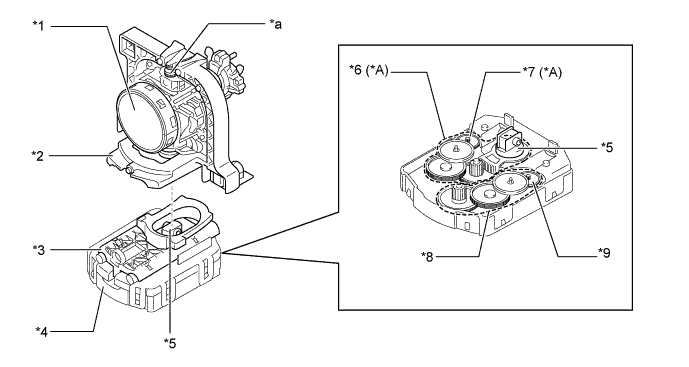
Text in Illustration *A Models with Intelligent AFS - - *1 Projector Unit *2 Bracket *3 Slider *4 Headlight Swivel Motor *5 Shaft *6 Swivel Operation Gear *7 Swivel Motor *8 Leveling Operation Gear *9 Leveling Motor - - *a Fulcrum of Projector Unit Operation - - -
When the swivel motor operates, it turns the shaft. The rotation of the shaft makes the projector unit move sideways, enhancing the lighting area.
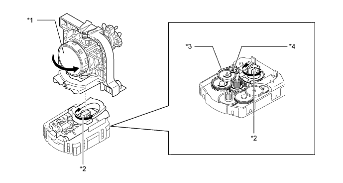
Text in Illustration *1 Projector Unit *2 Shaft *3 Swivel Operation Gear *4 Swivel Motor -
When the leveling motor operates, it moves the slider back and forth. The slider reciprocation makes the projector unit swing with its upper part as a fulcrum, changing the beam level.
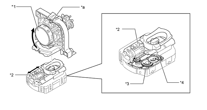
Text in Illustration *1 Projector Unit *2 Slider *3 Leveling Operation Gear *4 Leveling Motor *a Fulcrum of Projector Unit Operation - -
-
-
LED Headlight System
-
Projector Type LED Light
-
Through optimization of each reflector shape inside the lights, a large illumination range has been realized.
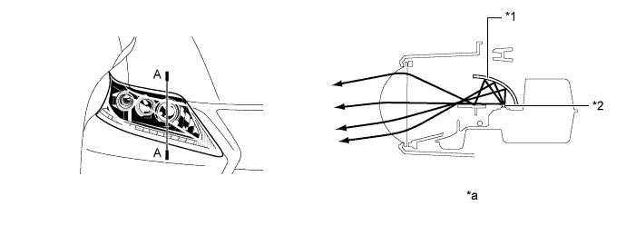
Text in Illustration *1 Reflector *2 LED *a A-A Cross Section - - -
-
Light Control ECU
-
When the light control switch is turned ON, the light control ECUs immediately turn on the LEDs (approximately 0.1 second). In addition, by regulating the output currents flowing into the LEDs at the specified level, the light control ECUs prevent the glare of light due to voltage variation.
-
If malfunctions occur in the LED headlight system, an light control ECU transmits fail signals to the main body ECU (multiplex network body ECU). When the main body ECU (multiplex network body ECU) receives fail signals, it transmits signals to the combination meter assembly, warning the driver.
-
-
-
-
FAIL-SAFE
-
HID Headlight System
-
The light control ECU executes the fail-safe actions listed below in accordance with the problem that has been detected.
Problem Outline Abnormal Input Voltage If the voltage that is input to the light control ECU deviates from the normal operating voltage (9 to 16 V), the light control ECU stops illuminating the headlights. It resumes illuminating the headlights once the voltage reverts to the normal operating voltage. However, if the input voltage decreases after the headlights have illuminated, the headlights will remain illuminated until the input voltage becomes insufficient to light the bulbs. Abnormal Output (Open Circuit or Short Circuit) If an abnormal condition (open or short) occurs in the voltage that is output by the light control ECU, the light control ECU stops illuminating the headlights and will maintain this state until the power is reinstated. Power is reinstated by turning the headlight dimmer switch (light control switch) from off to on. Bulb Open Circuit If a bulb is not inserted in its socket, the light control ECU stops generating high voltage until the bulb is inserted correctly and the power is reinstated. Power is reinstated by turning the headlight dimmer switch (light control switch) from off to on or turning the power switch from off to on (IG).
-
-
LED Headlight System
-
The light control ECU executes the fail-safe actions listed below in accordance with the problem that has been detected.
Problem Outline Abnormal Input Voltage If the voltage that is input to light control ECU deviates from the normal operating voltage (10 - 16 volts), the light control ECU stops illuminating the headlights. It resumes illuminating the headlights once the voltage reverts to the operating voltage range. Abnormal Output (Open Circuit or Short Circuit) If an abnormal condition (open or short) occurs in the voltage that is output by light control ECU, the light control ECU stops illuminating the headlights and will maintain this state until the power is reinstated. Power is reinstated by turning the light control switch from OFF to ON.
-
-
Intelligent Adaptive Front-lighting System (AFS)
-
If the AFS ECU (headlight swivel ECU assembly) detects a malfunction in the intelligent AFS, it will take the actions indicated in the table below.
Trouble Area System Operation AFS OFF Indicator Light Master Warning Light AFS ECU (Headlight Swivel ECU Assembly) Control is continued. - - Speed Sensor Signal
-
If a malfunction occurs only at one of the wheels, it doubles the vehicle speed detection value obtained from the normal wheel.
-
Stops operating after returning to the initial position.
Flashes Illuminates Rear Height Control Sensor Sub-assembly Signal Stops operating after returning to the initial position. Flashes Illuminates Steering Angle Sensor Signal 5 seconds after the malfunction occurs, the swivel actuators return to the initial position and operation stops. Flashes Illuminates Headlight Swivel Actuator The normal side swivel actuator comes to the initial position and the abnormal side swivel actuator stops in its current position. Flashes Illuminates Headlight Leveling Actuator Stops operating after returning to the initial position. Flashes Illuminates Communication Signal
-
Vehicle Speed Signal
Continues control. Flashes Illuminates Communication Signal
-
Other Signals
Stops operating after returning to the initial position. Flashes Illuminates -
-
-
Automatic Headlight Beam Level Control System
-
If the AFS ECU (headlight swivel ECU assembly) detects a malfunction in the automatic headlight beam level control system, it will take the actions indicated in the table below.
Trouble Area System Operation AFS OFF Indicator Light Master Warning Light AFS ECU (Headlight Swivel ECU Assembly) Stops at current condition. - - Speed Sensor Signal Continues control only when the vehicle is stopped. Flashes Illuminates Rear Height Control Sensor Sub-assembly Signal
-
Stops control after returning to initial position (If failure occurs at higher than initial position).
-
Stops control at current condition (If failure occurs at lower than initial position).
Flashes Illuminates Steering Angle Sensor Signal Continues control until a position of 0.65° less than the current position is reached, and resumes normal control after returning to the initial position. Flashes Illuminates Headlight Level Motor
-
Stops control after returning to initial position (If failure occurs at higher than initial position).
-
Stops control at current condition (If failure occurs at lower than initial position).
Flashes Illuminates Communication Signal
-
Vehicle Speed Signal
Continues control. Flashes Illuminates Communication Signal
-
Other Signals
Continues control. Flashes Illuminates -
-
-
-
DIAGNOSIS
-
LED Headlight System
-
When the main body ECU (multiplex network body ECU) detects malfunctions in the LED Headlight System, Diagnostic Trouble Codes (DTCs) are stored in memory.
-
The DTCs can be read using the intelligent tester. For details, refer to the Repair Manual.
-
-
Intelligent Adaptive Front-lighting System (AFS)
-
When the AFS ECU (headlight swivel ECU assembly) or main body ECU (multiplex network body ECU) detects malfunctions in the intelligent AFS, Diagnostic Trouble Codes (DTCs) are stored in memory.
-
The DTCs can be read using the intelligent tester. For details, refer to the Repair Manual.
-
-
Automatic Headlight Beam Level Control System
-
When the AFS ECU (headlight swivel ECU assembly) detects malfunctions in the automatic headlight beam level control system, Diagnostic Trouble Codes (DTCs) are stored in memory.
-
The DTCs can be read using the intelligent tester. For details, refer to the Repair Manual.
-
-
Automatic Light Control System
-
When the main body ECU (multiplex network body ECU) detects malfunctions in the automatic light control system, Diagnostic Trouble Codes (DTCs) are stored in memory.
-
The DTCs can be read using the intelligent tester. For details, refer to the Repair Manual.
-
-