AIRBAG SYSTEM DETAILS
-
FUNCTION OF MAIN COMPONENTS
-
The main components have the following functions:
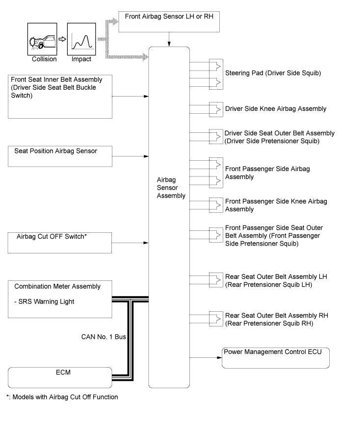
Component Function Airbag Sensor Assembly
-
The airbag sensor assembly receives signals from the deceleration sensor and safing sensor built into the airbag sensor assembly and one of the front airbag sensors and determines whether the driver airbag, front passenger airbag, driver side knee airbag, passenger side knee airbag and front seat belt pretensioners should be activated. It also diagnoses system malfunctions.
-
The airbag sensor assembly receives signals from the deceleration sensor and safing sensor built into the airbag sensor assembly, side airbag sensors and rear side airbag sensors and determines whether the front seat side airbag and curtain shield airbag should be activated. It also diagnoses system malfunctions.
-
The airbag sensor assembly sends an airbag deployment signal to the ECM through the Controller Area Network (CAN) to operate the fuel pump control.
-
The airbag sensor assembly sends an airbag deployment signal to the power management control ECU to shut down the hybrid system power supply.
Airbag Assembly Driver and Front Passenger The airbag assemblies are used as supplements to the seat belts to help reduce impact to the occupants. Driver and Passenger Side Knee Front Seat Side LH/RH Rear Seat Side LH/RH Curtain Shield LH/RH Front Airbag Sensor RH/LH Based on the deceleration of the vehicle during a frontal collision, a distortion is created in the sensor and converted into an electrical signal. Accordingly, the extent of the initial collision can be detected in detail. Side Airbag Sensor LH/RH Based on the deceleration of the vehicle during a side or rear side collision, a distortion is created in the sensor and converted into an electrical signal. Rear Side Airbag Sensor LH/RH Seat Position Airbag Sensor The seat position airbag sensor detects the slide position of the driver seat. Front Seat Outer Belt Assembly (Driver and Front Passenger) The front seat outer belt assemblies are used as supplements to help reduce impact to the occupants. Front Seat Inner Belt Assembly (Driver) Seat Belt Buckle Switch The seat belt buckle switch detects if the driver seat belt is fastened. Airbag Cut OFF Switch* The airbag cut OFF switch suspends the front passenger airbag assembly and the passenger knee airbag assembly operation. Power Management Control ECU The power management control ECU receives an airbag deployment signal from the airbag sensor assembly during a frontal collision or rollover. The power management control ECU will shut down the entire power supply by turning the System Main Relays (SMRs) OFF, in order to ensure safety. Combination Meter Assembly SRS Warning Light The SRS warning light illuminates to alert the driver when the airbag sensor assembly detects a malfunction in the airbag system. Multi-information Display The multi-information display alerts the driver when the airbag sensor assembly detects a malfunction in the airbag system. Accessory Meter AIRBAG ON/OFF Indicator Lights The AIRBAG ON/OFF indicator lights inform the driver whether the front passenger airbag assembly, passenger side knee airbag assembly and front passenger outer belt assembly are in an active state or inactive state. Air Conditioning Control Panel
-
*: Models for Europe and destination package for Israel and Turkey
-
-
-
OPERATION
-
If the impact of a collision is greater than the specified value, the SRS is activated automatically. The airbag sensor assembly includes the safing sensor and deceleration sensor. The safing sensor is designed to turn on at a lower deceleration rate than the deceleration sensor.
-
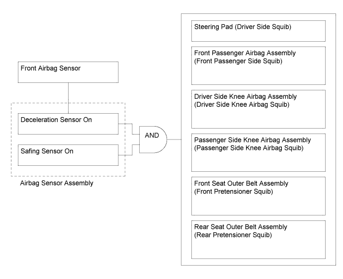
In the case of a frontal collision, the airbag sensor assembly determines whether airbag deployment or pretensioner activation is necessary based on signals from the deceleration sensor and the front airbag sensor. If the safing sensor turns on simultaneously, current flows to the squibs to deploy the SRS components as shown in the illustration below.
-
However, a deployment ignition signal may be output with the deceleration sensor on signal even without a signal from a front airbag sensor.
-
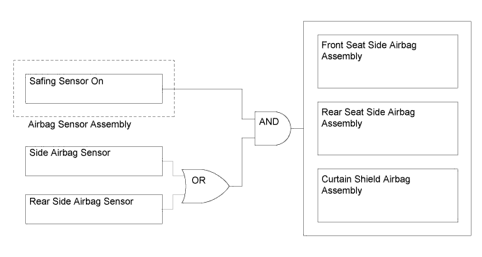
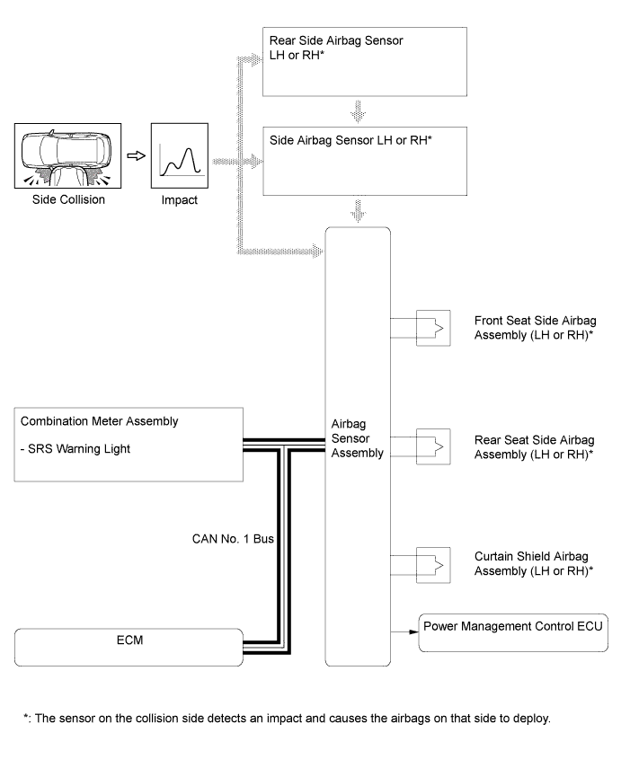
In the case of a side collision, the airbag sensor assembly determines whether airbag deployment is necessary based on signals from the side airbag sensor and rear side airbag sensor. If the safing sensor and either side airbag sensor turn on simultaneously, current flows to the squibs to deploy the SRS components shown in the illustration below.
-
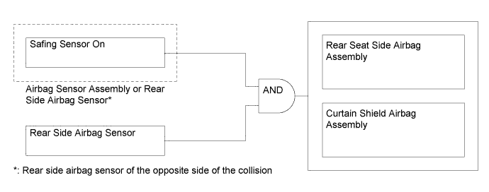
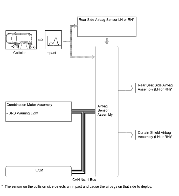
In the case of a rear side collision, the airbag sensor assembly determines whether airbag deployment is necessary based on signals from the airbag sensor assembly and rear side airbag sensor. If the safing sensor and rear side airbag sensor turn on simultaneously, current flows to the squibs to deploy the SRS components shown in the illustration below.
-
-
-
SYSTEM CONTROL
-
Airbag for Frontal Collision
-
There are 4 airbags which deploy in the event of a frontal collision: the steering pad, front passenger airbag assembly, driver side knee airbag assembly and passenger side knee airbag assembly. These airbags deploy simultaneously. The steering pad and front passenger airbag assembly use dual-stage control.
-
The airbag sensor assembly detects the information indicated below from various sources in order to activate the dual-stage control.
-
For a frontal collision, if a front airbag sensor detects an impact, it informs the airbag sensor assembly. The airbag sensor assembly causes the steering pad, front passenger airbag assembly, driver side knee airbag assembly and passenger side knee airbag assembly to deploy. Meanwhile, the airbag sensor assembly activates the seat belt pretensioners for the driver, front passenger and rear seat outer passengers.
Airbag Information Source Driver Extent of Impact
-
Front Airbag Sensor (RH or LH)
-
Airbag Sensor Assembly
Driver Seat Position Seat Position Airbag Sensor Seat Belt Condition Front Seat Inner Belt Assembly (Driver Seat Belt Buckle Switch) (Non-contact Type) Front Passenger Extent of Impact
-
Front Airbag Sensor (RH or LH)
-
Airbag Sensor Assembly
-
-
-
Airbag for Side/Side Rear Collision
-
There are 3 airbags which deploy in the event of a severe side collision: the front seat side airbag assembly, rear seat side airbag assembly and curtain shield airbag assembly. These airbags deploy simultaneously.
-
For a side collision, if the side airbag sensor detects an impact, it informs the airbag sensor assembly, and the airbag sensor assembly causes the front seat side, rear seat side and curtain shield airbag assemblies to deploy simultaneously.
-
For a rear side collision, if the rear side airbag sensor detects an impact, it informs the airbag sensor assembly. The airbag sensor assembly causes the rear seat side airbag assembly and curtain shield airbag assembly to deploy.
-
-
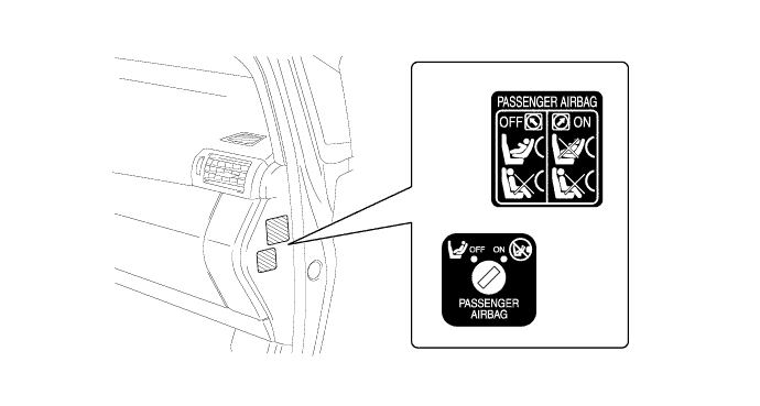
Airbag Cut OFF Switch*
-
The airbag cut OFF switch can be used if the deployment of the front passenger airbag assembly and the passenger knee airbag assembly is undesirable.
-
The ON/OFF switch can be operated by the mechanical key, which is supplied with the key. Once the airbag cut OFF switch is turned to OFF, the front passenger airbag assembly and the passenger knee airbag airbags will be disabled, regardless of any collision that occurs.
-
If deployment of the front passenger airbag assembly and the passenger knee airbag assembly has been disabled, the front passenger airbag OFF indicator light in the center cluster illuminates to inform the occupant.
*: Models with airbag cut off function
-
-
-
CONSTRUCTION
-
Airbag Sensor Assembly
-
The airbag sensor assembly consists of a deceleration sensor, safing sensor, roll rate sensor, ignition control circuit, backup power source, diagnostic circuit and memory circuit.
Item Outline Deceleration Sensor Deceleration sensors are built into the airbag sensor assembly, front airbag sensors, side airbag sensors and rear side airbag sensors. These sensors distort in the event of a collision. The amount of distortion is based on the deceleration rate of the vehicle during a frontal, side or side rear collision and is converted into an electric signal. Ignition Control Circuit The ignition control circuit performs calculations based on the signal output from the deceleration sensors of the airbag sensor assembly, front airbag sensors, side airbag sensors and rear side airbag sensors. If the calculated values are greater than the specified values, the airbags are deployed. Safing Sensor During a frontal, side or side rear collision, this sensor turns on and outputs an on signal to the airbag sensor assembly if the deceleration rate of the safing sensor is greater than a specified value. Backup Power Circuit The backup power circuit consists of a power supply capacitor and a DC-DC converter. When the power supply to the airbag sensor assembly is disrupted during a collision, the power supply capacitor discharges and supplies electric power to the system. The DC-DC converter operates as a boosting transformer when the battery voltage falls below a predetermined level. Diagnostic Circuit The diagnostic circuit constantly monitors for system malfunctions. When a malfunction is detected, it turns on the SRS warning light in the combination meter assembly to inform the driver. Memory Circuit When a malfunction is detected by the diagnostic circuit, a code is stored in memory.
-
-
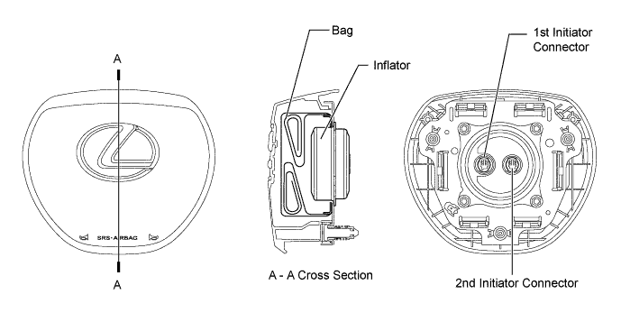
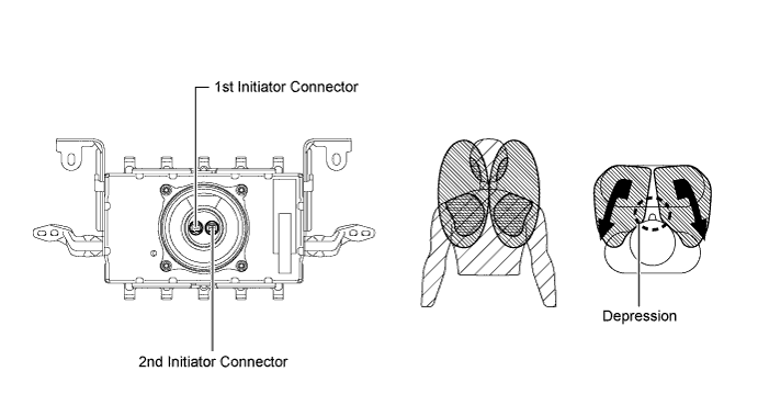
Steering Pad
-
The steering pad contains a set of 2 initiators and propellants. The airbag sensor assembly helps optimize the airbag deployment rate by controlling the ignition timing of the initiators.
-
-
Front Passenger Airbag Assembly
-
Front passenger airbag assembly contains a set of 2 initiators and propellants. The airbag sensor assembly helps optimize the airbag deployment rate by controlling the ignition timing of these initiators.
-
When the front passenger airbag assembly is deployed, it forms the shapes of 2 bags with a depression in the middle. Immediately after the airbag is deployed, the shapes of 2 bags support the occupant on many planes, including the head and shoulders. Thus, this airbag disperses the load that is applied to the occupant in order to lessen the localized impact that is applied to the occupant immediately upon deployment.
-
-
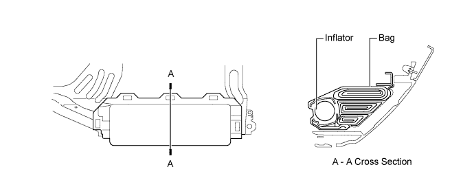
Driver Side Knee Airbag Assembly and Passenger Side Knee Airbag Assembly
-
The knee airbag assembly consists of an airbag door, inflator and bag.
-
-
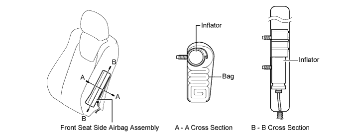
Front Seat Side Airbag Assembly
-
Each front seat side airbag assembly is a one-piece design, consisting of an inflator and bag.
-
-
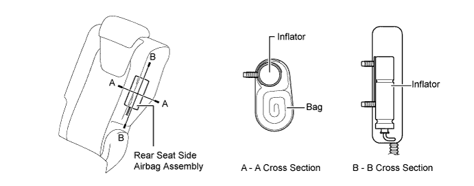
Rear Seat Side Airbag Assembly
-
Each rear seat side airbag assembly is a one-piece design, consisting of an inflator and bag.
-
-
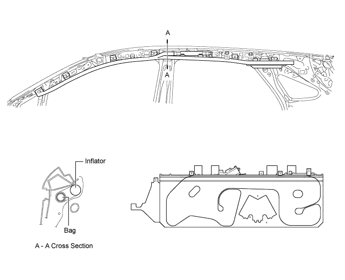
Curtain Shield Airbag Assembly
-
Each curtain shield airbag assembly is a one-piece design, consisting of an inflator and bag.
-
-
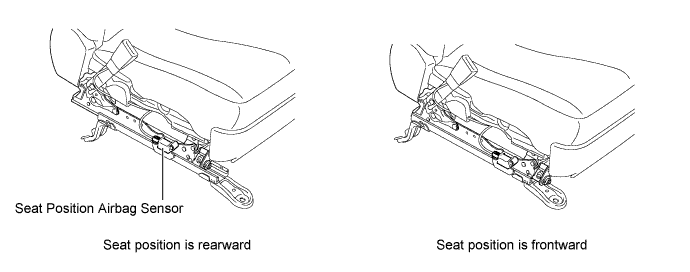
Seat Position Airbag Sensor
-
The seat position airbag sensor, which uses a Hall IC, detects changes in the magnetic flux that occurs due to the movement of the upper rail.
-
-
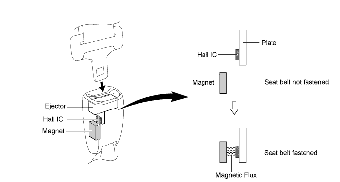
Front Seat Inner Belt Assembly (Seat Belt Buckle Switch)
-
A non-contact type switch is built into the front seat inner belt assembly (seat belt buckle switch) on the driver and front passenger side.
-
The non-contact type switch contains a Hall IC and magnet.
-
The ejector inside the front seat inner belt assembly (seat belt buckle switch) and the plate installed to the ejector move when the seat belt is removed or inserted. The movement of the plate changes the magnetic flux density of the magnet.
-
The Hall IC detects changes in the magnetic flux density. These changes indicate that the seat belt is either fastened or unfastened, and the Hall IC outputs a signal to the airbag sensor assembly.
-
-
-
DIAGNOSIS
-
If the airbag sensor assembly detects a malfunction in the SRS airbag system, the airbag sensor assembly stores the malfunction data in memory in addition to illuminating the SRS warning light.
-
The airbag sensor assembly stores the malfunction data 5-digit Diagnostic Trouble Codes (DTCs), to the intelligent tester.
-
The 5-digit DTCs can be read after connecting the intelligent tester to the DLC3. For details, refer to the Repair Manual.
-
If the SRS airbag deploys, the airbag sensor assembly will turn on the SRS warning light. However, unlike the ordinary diagnosis function, a DTC will not be stored. The SRS warning light cannot be manually turned off. It is necessary to replace the airbag sensor assembly with a new one.
-