ENTRY AND START SYSTEM DETAILS
-
FUNCTION OF MAIN COMPONENTS
-
The main components for the start function have the following functions:
Component Function Power Switch
-
Transponder Key Amplifier
-
Transmits the power switch signal to the power management control ECU.
-
Informs the driver of any power source or system abnormality through the illumination stage of the indicator light.
-
Receives the ID code and transmits it to the certification ECU (smart key ECU assembly) when the key battery is too weak to respond to the tuner based on the signals from the room oscillators.
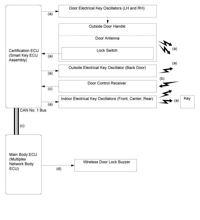
Key Receives the signals from the oscillators and returns the ID code to the door control receiver. Indoor Electrical Key Oscillator
-
Front, Center, Rear
Receives a request signal from the certification ECU (smart key ECU assembly) and forms the actuation area in the vehicle interior. Door Control Receiver Receives the ID code from the key and transmits it to the certification ECU (smart key ECU assembly). Power Management Control ECU
-
Switches the power source ("power switch") among 4 modes (off, on (ACC), on (IG), start) in accordance with the shift position and the brake pedal signal.
-
Turns on the SMR relays, and starts the hybrid control system when the power switch is pushed once with the brake pedal depressed.
-
Controls the entry and start system in accordance with the signals received from the switches and each ECU.
-
Receives the signal from the ID code box (immobiliser code ECU) and performs hybrid control system.
Certification ECU (Smart Key ECU Assembly)
-
Certifies the ID code received from the door control receiver and transmits the certification results to the ID code box (immobiliser code ECU) and steering lock ECU.
-
Transmits the steering lock/unlock signals.
-
Transmits the engine immobiliser set/unset request signals.
ID Code Box (Immobiliser Code ECU) Receives the steering unlock or engine immobiliser set/unset request signals from the certification ECU (smart key ECU assembly), certifies them, and transmits each set/unset request signal to the steering lock ECU or power management control ECU. Stop Light Switch Outputs the state of the brake pedal to the power management control ECU. Steering Lock ECU Receives the steering unlock/lock request signal from the ID code box (immobiliser code ECU), and activates the steering lock motor. Combination Meter Assembly Master Warning Light Illuminates to inform the driver of malfunctions in the entry and start system. Buzzer Sounds to inform the driver of malfunctions in the entry and start system. Multi-information Display The following warning messages appear to alert the driver.
-
KEY NOT DETECTED
-
DEPRESS BRAKE PEDAL AND PUSH POWER SWITCH TO START
-
KEY BATTERY LOW
-
STEERING LOCK ACTIVE
-
SHIFT TO P RANGE TO START
-
CHECK STEERING LOCK SYSTEM
-
DEPRESS BRAKE PEDAL, TOUCH POWER SWITCH WITH KEY
-
-
The main components in the entry function have the following functions:
Component Function Key
-
Outputs information such as the key ID and vehicle ID when request signals that are output by the room and door oscillators are received.
-
Outputs a request signal when the lock, unlock, panic, or power back door button on the key is pushed.
-
Outputs information such as the key ID and vehicle ID when the radio wave that is output by the transponder key amplifier in the power switch is received.
-
Has an integrated mechanical key that can be used to unlock the doors when the key battery is weak.
Main Body ECU (Multiplex Network Body ECU)
-
Receives a request signal from the certification ECU (smart key ECU assembly) and actuates the door lock motors to unlock or lock all the doors.
-
Transmits the condition of each door and the back door to the certification ECU (smart key ECU assembly).
Certification ECU (Smart Key ECU Assembly)
-
Certifies the ID code received from the door control receiver and transmits the certification results to the steering lock ECU.
-
Controls the oscillators and touch sensors.
-
Transmits the door lock/unlock request signals during the entry function.
Outside Door Handle Door Oscillator Receives a request signals from the certification ECU (smart key ECU assembly), and creates an actuation area around each front door. Lock Sensor Transmits door lock request signals to the certification ECU (smart key ECU assembly). Touch Sensor Detects when a person touches the inside of an outer door handle. Outside Electrical Key Oscillator Receives a request signal from the certification ECU (smart key ECU assembly), and forms an actuation area around the back door. Indoor Electrical Key Oscillator
-
Front, Center, Rear
Receives a request signal from the certification ECU (smart key ECU assembly) and forms the actuation area in the vehicle interior. Door Control Receiver Receives the ID code from the key and transmits it to the certification ECU (smart key ECU assembly). Back Door Opener Switch Transmits a back door open request signal to the main body ECU (multiplex network body ECU). Back Door Lock Switch Transmits a back door lock request signal to the main body ECU (multiplex network body ECU). Combination Meter Assembly Master Warning Light Illuminates simultaneously to inform the driver of malfunctions in the entry and start system. Buzzer Sounds to inform the driver of malfunctions in the entry and start system. Multi-information Display The following warning messages appear to alert the driver.
-
KEY NOT DETECTED
-
SHIFT TO P RANGE AND PUSH POWER SWITCH TO TURN POWER OFF
-
KEY BATTERY LOW
-
KEY DETECTED IN VEHICLE
-
TURN POWER OFF
Wireless Door Lock Buzzer
-
Sounds as an answer back for entry lock/unlock and wireless lock/unlock to inform the driver.
-
Sounds to inform the driver of malfunctions in the entry and start system.
Power Back Door Warning Buzzer*
-
Sounds to inform the driver that the system is operating.
-
Sounds if the operating conditions have not been met or if a jam has been detected.
Power Back Door ECU* Controls the power back door system in accordance with the signals received from the certification ECU (smart key ECU assembly). *: Models with Power Back Door System
-
-
-
OPERATION
-
The special functions of the entry and start system only work when the key is in the actuation area formed by the 6 oscillators.
-
The indoor electrical key oscillator (front), indoor electrical key oscillator (center), and indoor electrical key oscillator (rear) form the interior actuation area.
-
The door electrical key oscillator LH, door electrical key oscillator RH, and outside electrical key oscillator form the exterior actuation area.
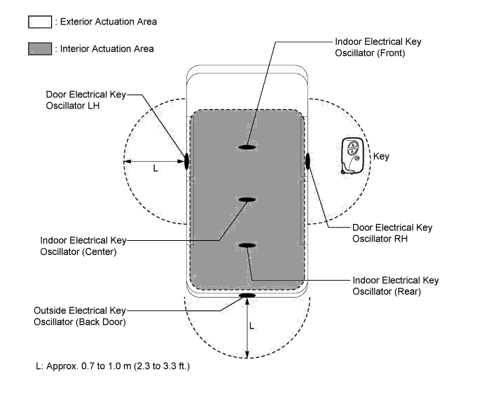
Actuation Area Detail Interior The interior actuation area of the indoor electrical key oscillators (front, center, rear) is formed when the driver door is opened or closed, when the power switch is pushed, when a warning is activated, or when the lock sensor is on. Exterior The exterior actuation area formed by the door electrical key oscillators (LH, RH) and outside electrical key oscillator (back door) is approximately 0.7 to 1.0 m (2.3 to 3.3 ft.) from the outside handle of the front doors, or the center of the rear bumper. Around Front Doors The exterior actuation area of the door electrical key oscillators (LH, RH) is formed by transmitting a request signal every 0.25 seconds while the power switch is off and each door is locked. In this way it detects the presence of a key. When locking the door using the lock sensor on the outer door handle, the actuation area is formed when the lock sensor is touched. Around Back Door The exterior actuation area of the outside electrical key oscillator (back door) is formed when the back door opener switch is on.
-
-
SYSTEM CONTROL
-
Start Function
-
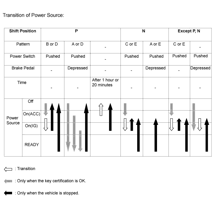
The start function has different power source patterns to suit the brake pedal state and shift lever position.
Pattern Brake Pedal Shift Lever Power Source Pattern A Depressed P When the power switch is pushed once.
-
Off → READY (The hybrid control system is started)
B Not Depressed P Each time the power switch is pushed.
-
Off → on (ACC) → on (IG) → off
C Except P Each time the power switch is pushed.
-
Off → on (ACC) → on (IG) → on (ACC)
D - P When the power switch is pushed in the on (IG) condition.
-
On (IG) (READY on or off) → off
E - Except P When the power switch is pushed in the on (IG) condition.
-
On (IG) (READY on or off) → on (ACC)
Note
-
Normally, the operation of the power switch is disabled while the vehicle is being driven. However, in an emergency, by pushing the power switch 3 times or more in a row or pushing the power switch for approximately 2 seconds or more, the driver can stop the hybrid control system while the vehicle is in motion.
-
If no signals are transmitted to the power management control ECU due to malfunctions in the stop light switch or shift lever position sensor, the hybrid control system may not start when the power switch is pushed with the brake pedal depressed. In such cases, performing the following procedure may enable the hybrid control system to start: 1) push the power switch to turn the power source from off to on (ACC), and 2) push the power switch again and hold it for 15 seconds or more.
-
The above 2 operations must be applied only in emergency situations. Under normal conditions, the hybrid control system must not be stopped by pushing the power switch while driving or should not be started without depressing the brake pedal or when the shift lever is in any position except P or N.
-
-
Pattern A: Off → READY (Hybrid control system is started)
Step System Operation (1) The driver, carrying the key, enters the vehicle. (2) When the brake pedal is depressed with the following conditions satisfied, the power management control ECU recognizes the stop light switch signal and transmits the key certification request to the certification ECU (smart key ECU assembly):
-
Shift lever is in P.
-
The power source is off.
(3) The certification ECU (smart key ECU assembly) receives the certification request and transmits a request signal to the oscillators (front, center, rear). These oscillators then form an actuation area. (4) The moment the key receives the request signal, it transmits its ID code to the door control receiver. The signal includes the response code. (5) The door control receiver receives this code and transmits it to the certification ECU (smart key ECU assembly). (6) The certification ECU (smart key ECU assembly) judges and certifies the ID code, and transmits a key certification OK signal to the power management control ECU. (7) Due to the brake pedal being depressed, the power management control ECU turns on the green indicator light of the power switch. (8) The driver pushes the power switch once, while the green indicator light of the power switch is illuminated. 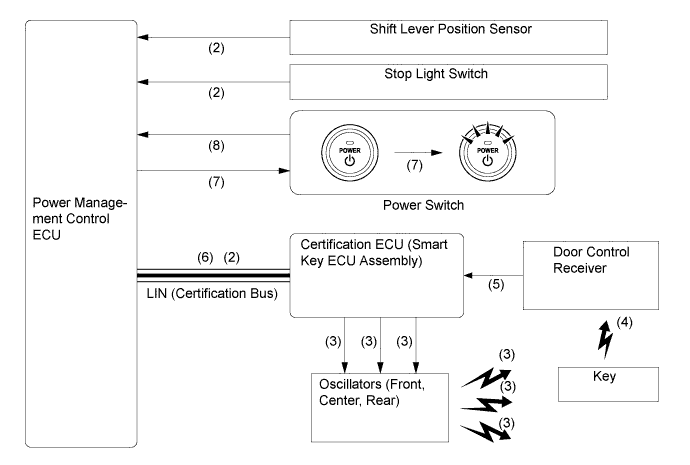
Step System Operation (9) After receiving the key certification OK signal, the power management control ECU turns on the ACC relay, and then turns on the IG1 and IG2 relays. (10) The certification ECU (smart key ECU assembly) checks that the power source has turned from off to on (IG), and transmits a steering unlock signal to the power management control ECU and ID code box (immobiliser code ECU). (11) The power management control ECU receives the steering unlock signal and supplies power to the steering lock ECU. (12) The steering lock ECU receives the steering unlock signal via the ID code box (immobiliser code ECU), and releases the steering lock. (13) After checking the steering unlock condition, the certification ECU (smart key ECU assembly) transmits an engine immobiliser disengage signal to the certification ECU and ID code box (immobiliser code ECU). (14) The ID code box (immobiliser code ECU) certifies the disengage signal of the certification ECU (smart key ECU assembly), transmits the engine immobiliser disengage signal to the power management control ECU, and disengages the engine immobiliser. 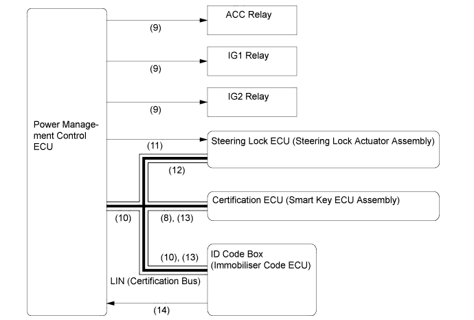
Step System Operation (15) After checking that the steering is in the unlocked condition, the power management control ECU start the hybrid control system. (16) The power management control ECU checks that the hybrid control system has started and turns off the indicator light of the power switch. 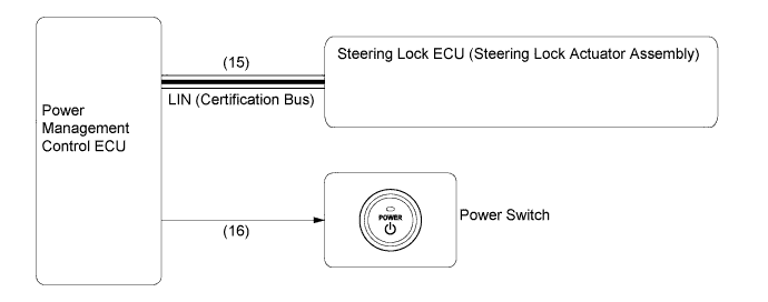
-
-
Pattern B: Off → On (ACC) → On (IG) → Off
OFF → On (ACC) Step System Operation (1) The driver, carrying the key, enters the vehicle. (2) When the power switch is pushed once with the following conditions satisfied, the power management control ECU recognizes the power switch signal and transmits the key certification request to the certification ECU (smart key ECU assembly)
-
The shift lever is in P.
-
The brake pedal is not depressed.
-
The power source is off.
(3) The rest of the system operation is the same as (3) to (6) in pattern A. (4) The power management control ECU turns on the ACC relays will turn on the amber indicator light of the power switch. (5) The rest of the system operation is the same as (10) to (14) in pattern A. On (ACC) → On (IG) Step System Operation (1) When the power source is on (ACC) and the driver pushes the power switch again, the power management control ECU recognizes the power switch signal and turns on the IG1 and IG2 relays. On (IG) → Off Step System Operation (1) When the power switch is pushed once with the following conditions satisfied, the power management control ECU recognizes the power switch signal and turns off the ACC, IG1 and IG2 relays.
-
The shift lever is in P.
-
The brake pedal is not depressed.
-
The vehicle speed is 0 km/h (0 mph).
-
The power source is on (IG).
(2) When the power source is changed from on (IG) to off, the power management control ECU will turn off the indicator light of the power switch. (3) When the certification ECU recognizes that the power source is off, it transmits the engine immobiliser set signal to the ID code box (immobiliser code ECU). (4) The ID code box (immobiliser code ECU) certifies that the certification ECU (smart key ECU assembly) signal is appropriate, transmits the engine immobiliser set signal to the power management control ECU, and sets the engine immobiliser. (5) If the driver door is opened, the certification ECU receives a signal from the main body ECU (multiplex network body ECU). After that, the certification ECU transmits the steering lock signal to the power management control ECU. (6) The power management control ECU receives the steering lock signal and supplies power to the steering lock ECU. (7) The steering lock ECU operates the lock motor until the steering lock is engaged if the ID code box (immobiliser code ECU) certifies that the certification ECU (smart key ECU assembly) is appropriate. 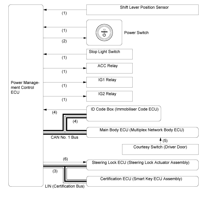
-
-
Pattern C: Off → On (ACC) → On (IG) → On (ACC)
Step System Operation (1) The system operations for pattern C (off → on (ACC) → on (IG)) are the same as those in pattern B. (2) When the power switch is pushed once with the following conditions satisfied, the power management control ECU recognizes the power switch signal and turns off the IG1 and IG2 relays.
-
The shift lever is in any position except P.
-
The brake pedal is not depressed.
-
The vehicle speed is 0 km/h (0 mph).
-
The power source is on (IG).
(3) Even after the power switch turned from on (IG) to on (ACC), the indicator light of the power switch will remain illuminated in amber. 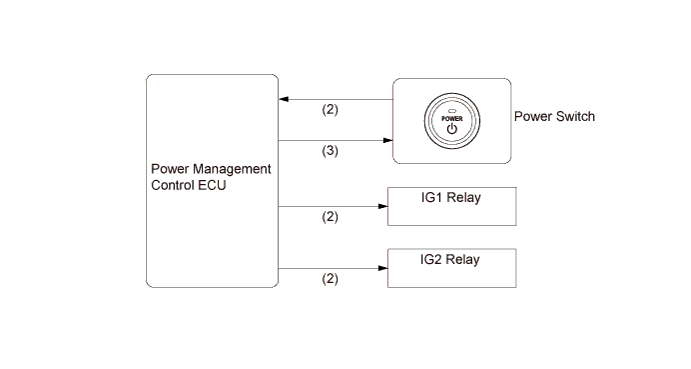
-
-
Pattern D: READY → Off
Step System Operation (1) When the power switch is pushed once with the following conditions satisfied, the power management control ECU recognizes the power switch signal and turns off the ACC, IG1 and IG2 relays.
-
The shift lever is in P.
-
The vehicle speed is 0 km/h (0 mph).
-
The power source is on (IG).
(2) The rest of the system operation is same as (3) to (7) of the "on (IG) → off" in pattern B. -
-
Pattern E: READY → On (ACC)
-
This system operation is the same as for pattern C. However, the indicator light of the power switch will illuminate as follows:
-
When the power source is changed from READY to on (ACC), the power management control ECU continues to illuminate the amber indicator light of the power switch.
-
When the hybrid control system is turned off using the power switch (power source mode is changed to off), the power management control ECU turns off the indicator light of the power switch.
-
-
When a key battery is weak.
Step System Operation (1) To operate the entry and start system when the key battery is weak, depress the brake pedal and hold the key against the power switch as shown in the illustration. (2) The power management control ECU receives the stop light switch signal and transmits a key certification request signal to the certification ECU (smart key ECU assembly). (3) The certification ECU (smart key ECU assembly) does not receive an ID code response from the door control receiver, so it actuates the transponder key amplifier built into the power switch. (4) The transponder key amplifier outputs an engine immobiliser radio wave signal to the key. (5) The key receives the radio wave signal, and returns a radio wave signal response to the transponder key amplifier. (6) The transponder key amplifier combines the key ID codes with the radio wave signal response, and transmits it to the certification ECU (smart key ECU assembly). (7) The certification ECU (smart key ECU assembly) judges and verifies the ID code, and transmits a key certification OK signal to the power management control ECU. The buzzer in the combination meter assembly sounds once. (8) After the buzzer sounds, if the power switch is pushed within 10 seconds while the brake pedal is depressed, the hybrid control system will be started, the same as with normal smart key operation. (9) After the buzzer sounds, if the power switch is pushed within 10 seconds while the brake pedal is not depressed, the power source mode will change to on (ACC) or on (IG), the same as with normal smart key operation. 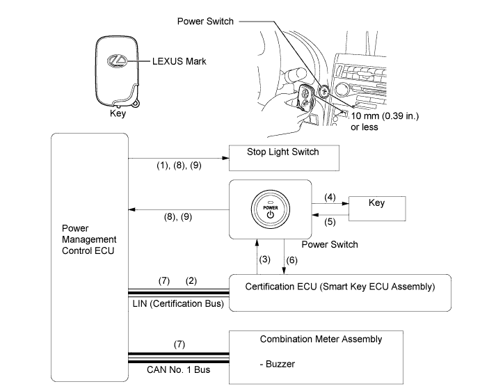
-
-
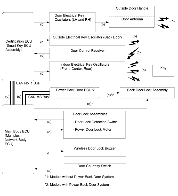
Entry Function
-
The entry function consists of the following functions:
Function Outline Wireless Door Lock Control This function is a convenient system for locking and unlocking all the doors and back door at a distance. The operation of this function is the same as that in the wireless door lock control system. Entry Illumination When a key enters the exterior actuation area of the door electrical key oscillators (LH and RH), the foot lights illuminate. Entry Unlock When a key is located in the exterior actuation area of any door electrical key oscillator, the door will unlock after the inner part of either front outside door handle is touched.
-
The driver outside door handle unlocks the driver door.
-
The front passenger outside door handle unlocks all doors and the back door.
Entry Unlock Mode Switching Allows switching between 2 modes that can be operated with the entry unlock function.
-
Driver Door Mode (Default Setting)
-
All Door Mode
Entry Lock When a key is located in the exterior actuation area of any electrical key oscillator (driver, front passenger or back door) and the power switch is off, all doors can be locked by simply touching the lock sensor. Back Door Open When a key is in an exterior actuation area of the outside electrical key oscillator (back door), the back door opens manually by simply pushing the back door opener switch. Prevention of Key Confinement The key confinement prevention function prevents the vehicle from being locked with a key left inside it. This function operates in 2 different situations: when the lock knob is used (keyless lock) and when an outside door handle lock sensor is used (lock sensor). Warning When any of the situations below occur, the entry and start system causes the certification ECU (smart key ECU assembly) to sound the buzzer in the combination meter and the wireless door lock buzzer, and indicates a warning on the multi-information display in order to alert the driver.
-
An exit warning is activated if the shift lever is in any position except P and the power switch is in a mode other than off.
-
An exit warning is activated if the shift lever is in P and the power switch is in a mode other than off.
-
A warning is activated if the occupant leaves with the key in inappropriate circumstances.
-
A warning is activated if the power switch is operated while the key is outside the actuation area.
-
A warning is activated if the lock button is operated while the key is inside the vehicle.
-
A warning is activated if the key battery is weak.
Battery Saving If the key remains within the exterior actuation area of any electrical key oscillator (driver, front passenger, or back door), the system maintains periodic communication with the key. Therefore, if the vehicle remains parked in that state for a long time, the key battery and the vehicle battery could be drained. Key Cancel The following key functions can be cancelled by following certain procedures.
-
Entry unlock/lock
-
Back door open
-
Prevention of key confinement
-
Warning
Key Code Registration A total of 7 keys can be registered. Key registration enables the registering (writing and storing) of transmitter recognition codes in the EEPROM that is contained in the certification ECU (smart key ECU assembly). -
-
The wireless door lock control system allows the following customizable functions:
Function Outline Customizable*1 All Doors Lock Pressing the lock button of the key locks doors. *2 All Doors Unlock (2-step Unlock) Pressing the unlock button of the key twice within 3 seconds unlocks all doors after it first unlocks the driver's door. *3 All Doors Unlock (1-step Unlock) Pressing the unlock button of the key once with the key unlocks all doors. *2 Power Back Door Open/Close Keeping the power back door button of the key pushed longer than about 0.8 seconds opens or closes the back door. *2 Answer Back When the doors are being locked or unlocked using the key, the wireless door lock buzzer sounds*4 and the hazard warning lights blink once while locking and twice while unlocking. Also, the answer back function operates when the doors are locked by the automatic relock function. *2 Answer Back (for Power Back Door) When the key is used for opening or closing the power back door, this function sounds the wireless door lock buzzer*4 and power back door buzzer once to inform the user that door operation has started. *2 Panic Alarm*4 Keeping the panic button of the key pushed longer than about 0.8 seconds causes the following to activate as an alarm:
-
The horn and security horn are sounded.
-
The hazard warning lights, headlights, and taillights are flashed.
-
The interior lights are illuminated (If the dome switch is in the DOOR position).
*2 Automatic Relock If none of the doors are opened within 30 seconds after they are unlocked using the wireless door lock remote control, all the doors will be locked again automatically. *2 Repeat If a door is not locked in response to the locking operation of the key, the main body ECU (multiplex network body ECU) will output a lock signal again after 1 second elapses. Standard (Not Customizable) Security Sends a door lock/unlock operation request signal as a rolling code. Standard (Not Customizable) Door Ajar Warning*4 If any door is open or ajar, pushing the lock button of the key will cause the wireless door lock buzzer to sound for about 10 seconds as a warning. Standard (Not Customizable)
-
*1: The customize settings can be turned on/off using the customized body electronics system. For details, refer to the Repair Manual.
-
*2: Default setting is on.
-
*3: Default setting is off.
-
*4: Models except for Europe and destination package for China
-
-
Entry Unlock
Step System Operation (1) When the key enters any exterior actuation area of a front door, the certification ECU (smart key ECU assembly) judges and certifies the key ID code received from the door control receiver. (2) After the key certification OK is confirmed, the certification ECU (smart key ECU assembly) transmits an unlock stand-by signal to the touch sensor of the relevant door. (3) At the same time, the certification ECU (smart key ECU assembly) transmits the lighting signals to the foot light on the outside rear view mirror and the interior lights (power switch illumination and interior lights) to turn them on (Entry Illumination Function). (4)
-
If a touch sensor is touched in this condition, the certification ECU (smart key ECU assembly) transmits a door unlock request signal to the main body ECU (multiplex network body ECU), and unlocks either the driver door or all doors.
-
The driver outside door handle unlocks the driver door.
-
The front passenger outside door handle unlocks all doors.
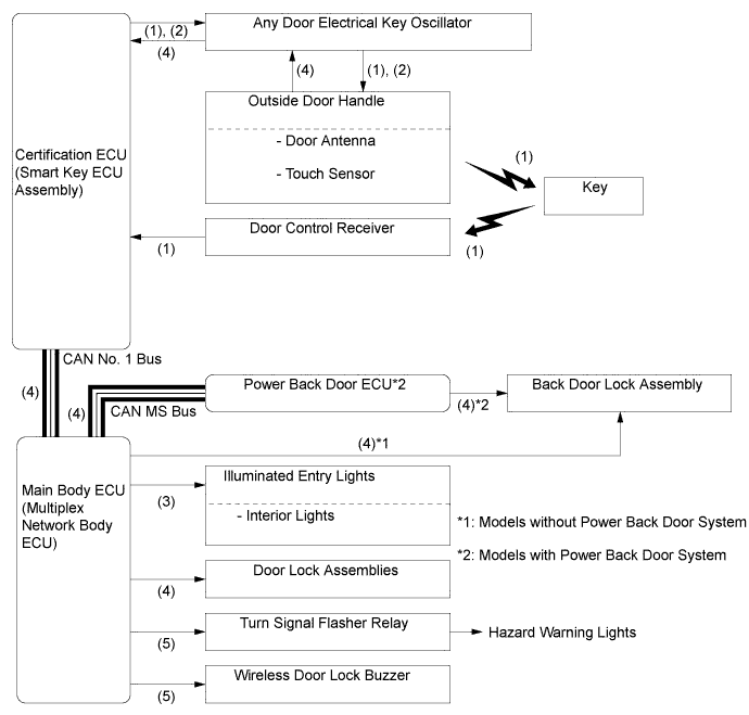
(5) The main body ECU (multiplex network body ECU) sounds the wireless door lock buzzer twice*, and flashes the hazard warning lights twice, as an answer back for entry unlock. *: Except for Europe and destination package for China
-
-
Entry Unlock Mode Switching
Step System Operation (1) When the power switch is off, push the lock button and one of the other buttons on the key at the same time for approximately 5 seconds while the key is in the actuation area. (2) The certification ECU (smart key ECU assembly) receives this signal from the door control receiver and switches the entry unlock mode. (3) The main body ECU (multiplex network body ECU) sounds the wireless door lock buzzer to inform the user that the mode has been switched. (4) If the entry unlock mode needs to be switched again, push the lock button and one of the other three buttons on the key at the same time for approximately 5 seconds after the LED of the key goes off. 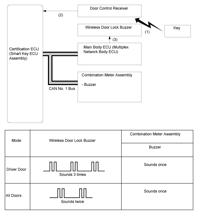
Tech Tips
This function only switches the entry unlock mode of the entry and start system. It is not applied to the unlock function using the wireless door lock control.
-
Entry Lock
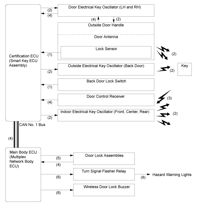
Step System Operation (1) An entry lock signal is transmitted to the certification ECU (smart key ECU assembly) when the user, while carrying the key, touches the lock sensor or the back door lock switch after exiting the vehicle. (2) The certification ECU (smart key ECU assembly) transmits a request signal for the indoor electrical key oscillators (front, center, rear) and electrical key oscillators (driver, front passenger, back door) to form actuation areas. (3) The key receives this signal and returns the ID code to the door control receiver. (4) The certification ECU (smart key ECU assembly) receives the ID code from the door control receiver, and then judges and certifies the ID code. It then checks the location of the key and, if all the doors are closed, the ECU transmits a door lock signal to the main body ECU (multiplex network body ECU). (5) The main body ECU (multiplex network body ECU) receives this signal and actuates the lock motors. (6) The main body ECU (multiplex network body ECU) blinks the hazard warning lights once and sounds the wireless door lock buzzer once* as an answerback for the entry lock function. *: Models except for Europe and destination package for China
-
Entry Back Door Open
Step System Operation (1) The unlock signal is transmitted to the certification ECU (smart key ECU assembly) when the driver pushes the back door opener switch while carrying the keys. (2) The certification ECU (smart key ECU assembly) transmits a request signal for indoor electrical key oscillators (front, center, rear), door electrical key oscillators (LH and RH) and outside electrical key oscillator (back door) to form actuation areas. (3) The key receives this signal and returns the ID code to the door control receiver. (4) The certification ECU (smart key ECU assembly) receives the ID code from the door control receiver, and then judges and certifies the ID code, and checks the location of the key. The ECU transmits a back door open signal to the main body ECU (multiplex network body ECU) or power back door ECU. (5) The ECU that receives this signal actuates the motor to open the back door. 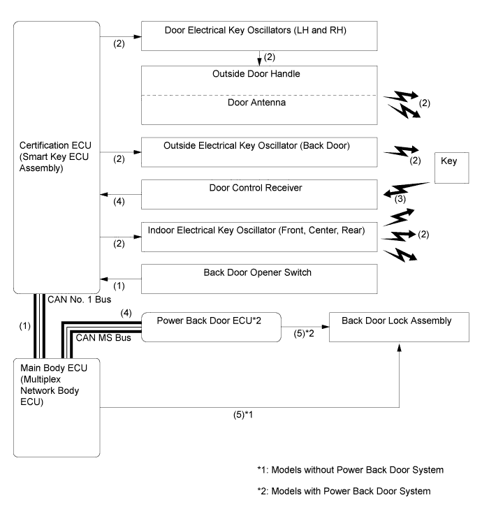
-
Memory Call Function
-
The key linked memory call function uses the ID of a key to automatically restore the seat position (using the driving position memory system), tilt and telescopic position and outside rear view mirror position, increasing driver convenience.
Condition Outline Memory Registration When all the following conditions are met, the key ID will be recorded.
-
The power switch is on (IG).
-
The memory switch (M1, M2 or M3) button is pushed and held.
-
Push the lock or unlock side of the driver door lock switch.
Memory Call Operation After the door is unlocked using the entry and start system or wireless door lock control function, when the driver door is opened the memory call function operates. Memory Call Cancel When all the following conditions are met, the memory call function can be disabled.
-
The power switch is on (IG).
-
The driver door is closed.
-
The SET button is pushed and held.
-
The lock or unlock button on the key is pushed and held.
-
-
The key linked memory call function uses the ID of a key to automatically restore the last settings used for the air conditioning system.
The function is available for vehicles without the driving position memory system. For details, refer to the Repair Manual.
-
Memory Registration
Step System Operation (a) Carrying the key to be linked to the seat position memory system, close the door and turn the power switch on (IG). Push the memory switch that is to be linked to the key. (b) While continuing to the memory switch, push the lock or unlock side of the driver door lock switch. (c) During key ID detection, the buzzer in the position control ECU and switch assembly sounds continuously. (d) The main body ECU (multiplex network body ECU) registers the key ID and each position into memory. (e) When the main body ECU (multiplex network body ECU) completes recording, it beeps the buzzer in the position control ECU and switch assembly for 0.5 seconds as an answer back. When recording faults, it beeps the buzzer in the position control ECU and switch assembly for 3 seconds as an answer back. 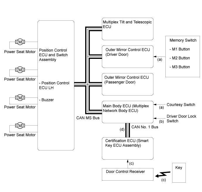
-
Memory Call Operation
Step System Operation (a) When the unlock button on the key is pushed or the key enters the actuation area, the key ID is sent to the certification ECU (smart key ECU assembly) through the door control receiver. (b) The certification ECU (smart key ECU assembly) transmits the key ID to the main body ECU (multiplex network body ECU). (c) If the driver door is opened, the main body ECU (multiplex network body ECU) outputs a key ID memory restoration signal from certification ECU (smart key ECU assembly) to each ECU and activates the drive seat motors. (d) When each ECU receives this signal, it activates its respective actuator. (e) When the power switch is turned on (IG), the air conditioning setting is recalled. 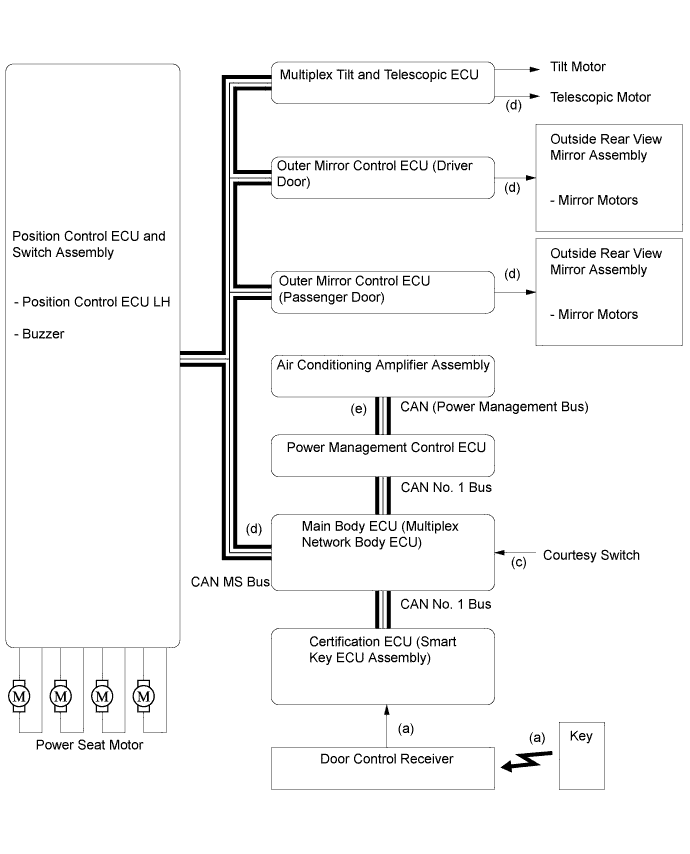
-
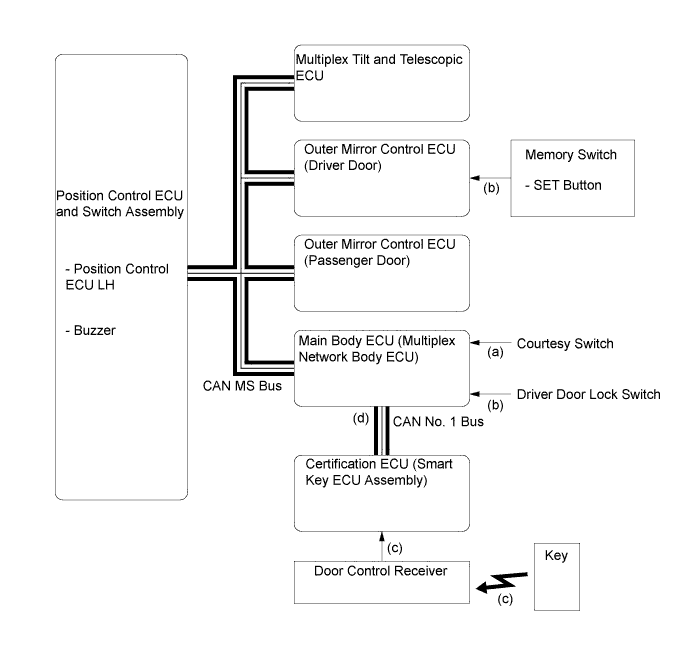
Memory Call Cancel
Step System Operation (a) Carrying the key to be linked to the seat position memory system, close the door and turn the power switch on (IG). (b) Push and hold the SET switch, push the lock or unlock side of the driver door lock switch. (c) During key ID detection, the buzzer in the position control ECU and switch assembly sounds continuously. (d) If the key ID has already been registered, the main body ECU (multiplex network body ECU) will cancel the key ID memory call function. To use the key ID memory call function again, it is necessary to re-register the key ID. (e) When the main body ECU (multiplex network body ECU) completes canceling, it beeps the buzzer in the position control ECU and switch assembly twice for 0.1 second as an answer back.
When canceling faults, it beeps the buzzer in the position control ECU and switch assembly for 3 seconds as an answer back.
-
-
Prevention of Key Confinement
-
The key confinement prevention function prevents the key from being locked inside the vehicle. This function operates in 2 different situations: keyless lock and lock sensor.
Keyless Lock (Doors locked using lock knobs): Step System Operation (a) When the door is locked by the lock knob in the inside door handle while the key is still in the vehicle, the main body ECU (multiplex network body ECU) receives this signal and transmits the door condition signal to the certification ECU (smart key ECU assembly). (b) The certification ECU (smart key ECU assembly) transmits a request signal for the indoor electrical key oscillators (front, center, rear), door electrical key oscillators (LH and RH) and outside electrical key oscillator (back door) to form actuation areas. (c) The key receives this signal and returns the ID code to the door control receiver. (d) The certification ECU (smart key ECU assembly) receives the ID code from the door control receiver, and then judges and certifies the ID code, and checks the location of the key. The ECU transmits a door unlock signal to the main body ECU (multiplex network body ECU). (e) The main body ECU (multiplex network body ECU) receives this signal and unlocks all the door lock assemblies. (f) The main body ECU (multiplex network body ECU) sounds the wireless door lock buzzer.* *: Models except for Europe and destination package for China
Lock Sensor (Doors locked using outside handle lock sensor): Step System Operation (a) When the door is locked from the lock sensor while the key is still in the vehicle interior, the certification ECU (smart key ECU assembly) receives this signal and transmits a request signal for the indoor electrical key oscillators (front, center, rear), door electrical key oscillators (LH and RH) and outside electrical key oscillator (back door) to form actuation areas. (b) The key receives this signal and returns the ID code to the door control receiver. (c) The certification ECU (smart key ECU assembly) receives the ID code from the door control receiver, and then judges and certifies the ID code, and check the location of the key. (d) The main body ECU (multiplex network body ECU) sounds the wireless door lock buzzer.* *: Models except for Europe and destination package for China
-
-
-
Warning
-
When any of the situations below occur, the entry and start system sounds the wireless door lock buzzer, sounds a buzzer in the combination meter assembly, displays a message on the multi-information display, and illuminates the power switch indicator in order to alert the driver.
Situation Condition A The hybrid control system is left running and the shift lever is in a position other than P when the driver gets out of the vehicle. B The key reminder sounds. C The hybrid control system is left running and the shift lever is in P when the driver gets out of the vehicle. D A door is ajar. E The hybrid control system is left operating when a passenger gets out of the vehicle while holding the key. F The key is not within the actuation areas. G The key is left in the vehicle. H The key battery is weak. I Steering lock does not release. J The steering lock mechanism is malfunctioning. K The power management control ECU is malfunctioning. L The hybrid control system cannot be started (driver error) M The hybrid control system cannot be started (system error) N An attempt is made to turn off the vehicle with the shift lever in a position other than P or N. O Auto power off operation occurs. P Immobiliser system certification completion occurs. Q The vehicle is driven without a key. -
Situation A
-
There are 2 patterns for situation A.
-
Pattern 1:
When the shift lever is in a position other than P, the power switch is in a mode other than off, the driver opens the door and attempts to get out of the vehicle.
In this situation, the following control is performed:
Possible Effects without Warning Sudden vehicle movement, Vehicle theft, Vehicle roll-away Warning Active Condition The warning is activated when all of the following conditions are met:
-
The power switch is in a mode other than off.
-
The shift lever is in any position except P.
-
The vehicle speed is 0 km/h (0 mph).
-
The driver door is opened.
Warning Method Combination Meter Assembly Buzzer Sounds continuously Master Warning Light Blinks Multi-information Display The following warning message is alternately displayed:
-
SHIFT TO P RANGE
Wireless Door Lock Buzzer* - Power Switch Illumination - Warning Stop Condition The warning is stopped when one of the following conditions is met:
-
The power switch is turned off.
-
The shift lever is moved to P.
-
The vehicle speed is above 0 km/h (0 mph).
-
The driver door is closed.
*: Except destination package for China
-
-
Pattern 2:
Under the situation of pattern 1, the driver closes the door and attempts to leave the vehicle while holding the key.
In this situation, the following control is performed:
Possible Effects without Warning Sudden vehicle start-off, Vehicle theft, Vehicle roll-away Warning Active Condition The warning is activated when all of the following conditions are met:
-
The shift lever is in any position except P.
-
The power switch is in a mode other than off.
-
The vehicle speed is 0 km/h (0 mph).
-
The key is not in the vehicle.
-
The driver door is opened → closed.
Warning Method Combination Meter Assembly Buzzer Sounds continuously Master Warning Light Blinks Multi-information Display The following warning messages are alternately displayed:
-
SHIFT TO P RANGE
-
KEY NOT DETECTED
Wireless Door Lock Buzzer* Sounds continuously Power Switch Illumination - Warning Stop Condition The warning is stopped when one of the following conditions is met: Combination Meter Assembly Buzzer
-
The power switch is turned off.
-
The shift lever is moved to P.
-
The vehicle speed is above 0 km/h (0 mph).
-
The key is detected in the vehicle.
Wireless Door Lock Buzzer Combination Meter Assembly Master Warning Light No messages are displayed on the multi-information display. Multi-information Display ("KEY NOT DETECTED" message displayed)
-
The power switch is turned off.
-
The key is detected in the vehicle.
Multi-information Display ("SHIFT TO P RANGE" message displayed)
-
The shift lever is moved to P.
-
The vehicle speed is above 0 km/h (0 mph).
*: Except destination package for China
-
-
-
Situation B
-
There are 2 patterns for situation B.
-
Pattern 1:
When the driver door is open, the driver turns the power switch on (ACC) and attempts to leave the vehicle.
-
Pattern 2:
When the driver door is open, the driver turns the power switch from on (IG) to off and attempts to leave the vehicle.
In these situations, the following control is performed:
Possible Effects without Warning Vehicle theft Warning Active Condition The warning is activated when either of the following conditions is met:
-
The power switch is on (ACC) and the driver door is opened.
-
The power switch is off, the steering is unlocked, and the driver door is opened.
Warning Method Combination Meter Assembly Buzzer Sounds continuously at short and even intervals Master Warning Light - Multi-information Display - Wireless Door Lock Buzzer* - Power Switch Illumination - Warning Stop Condition The warning is stopped when one of the following conditions is met:
-
The power switch is turned on (IG).
-
The driver door is closed.
-
The power switch is turned off and the steering is locked.
*: Except destination package for China
-
-
Situation C
-
There are 2 patterns for situation C.
-
Pattern 1:
When the shift lever is in P, the power switch is in a mode other than off, the driver closes the driver door and attempts to leave the vehicle while holding the key.
In this situation, the following control is performed:
Possible Effects without Warning Vehicle theft, Hybrid control system cannot be restarted, Discharged battery Warning Active Condition The warning is activated when all of the following conditions are met:
-
The shift lever is in P.
-
The power switch is in a mode other than off.
-
The key is not detected in the vehicle.
-
The driver door is opened → closed.
Warning Method Combination Meter Assembly Buzzer Sounds once Master Warning Light Blinks Multi-information Display The following warning message is displayed:
-
KEY NOT DETECTED
Wireless Door Lock Buzzer* Sounds 3 times* Power Switch Illumination - Warning Stop Condition The warning is stopped when either of the following conditions is met:
-
The power switch is turned off.
-
The key is detected in the vehicle (within one of the actuation areas).
*: Except destination package for China
-
-
Pattern 2:
Under the situation of pattern 1, the driver touches the lock sensor on the door outside handle.
In this situation, the following control is performed:
Possible Effects without Warning Vehicle theft, Discharged battery Warning Active Condition The warning is activated when all of the following conditions are met:
-
The power switch is in a mode other than off.
-
The shift lever is in P.
-
All doors are closed.
-
The key is not detected in the vehicle interior (within one of the actuation areas).
Warning Method Combination Meter Assembly Buzzer Sounds once Master Warning Light Blinks Multi-information Display The following warning message is displayed:
-
TURN POWER OFF
Wireless Door Lock Buzzer* Sounds for 5 seconds Power Switch Illumination - Warning Stop Condition The warning is stopped when one of the following conditions is met: Combination Meter Assembly Master Warning Light
-
The power switch is turned off.
-
The shift lever is moved to any position except P.
-
The vehicle speed is above 0 km/h (0 mph).
Multi-information Display Wireless Door Lock Buzzer
-
Any door is opened.
-
The power switch is off.
-
The shift lever is moved to any position except P.
-
The vehicle speed is above 0 km/h (0 mph).
-
The key is detected in the vehicle.
*: Except destination package for China
-
-
-
Situation D
-
The lock sensor on the door outside handle is pushed to perform entry lock, however a door is open.
In this situation, the following control is performed:
Possible Effects without Warning Vehicle theft Warning Active Condition The warning is activated when all of the following conditions are met:
-
The power switch is off.
-
Any door is open.
-
The lock sensor on the outer door handle is on (touched).
Warning Method Combination Meter Assembly Buzzer - Master Warning Light - Multi-information Display - Wireless Door Lock Buzzer* Sounds for 5 seconds Power Switch Illumination - Warning Stop Condition The warning is stopped when one of the following conditions is met:
-
The power switch is turned to a mode other than off.
-
All doors are closed.
-
An unlock operation is performed using the wireless door lock remote function.
-
The touch sensor on the inside of an outer door handle is used to perform entry unlock.
*: Except destination package for China
-
-
-
Situation E
-
When the hybrid control system is left operating, a passenger leaves the vehicle while holding the key.
In this situation, the following control is performed:
Possible Effect without Warning Hybrid control system cannot be restarted Warning Active Condition The warning is activated when all of the following conditions are met:
-
The power switch is in a mode other than off.
-
A door other than the driver door is opened → closed.
-
The vehicle speed is 0 km/h (0 mph).
-
The key is not detected in the vehicle.
Warning Method Combination Meter Assembly Buzzer Sounds once Master Warning Light Blinks Multi-information Display The following warning message is displayed:
-
KEY NOT DETECTED
Wireless Door Lock Buzzer* Sounds 3 times Power Switch Illumination - Warning Stop Condition The warning is stopped when either of the following conditions is met:
-
The power switch is turned off.
-
The key is detected again or returned to the vehicle.
*: Except destination package for China
-
-
-
Situation F
-
When the key is not in the vehicle or the key battery is dead, the driver attempts to start the hybrid control system or turn the power switch on (IG).
In this situation, the following control is performed:
Possible Effect without Warning User becomes confused Warning Active Condition The warning is activated when both of the following conditions are met:
-
The power switch is pushed.
-
The key is not in the vehicle (or the key battery is dead).
Warning Method Combination Meter Assembly Buzzer Sounds once Master Warning Light Blinks for 10 seconds Multi-information Display The following warning message is displayed for 10 seconds (and then automatically turned off).
-
KEY NOT DETECTED
Wireless Door Lock Buzzer* - Power Switch Illumination - Warning Stop Condition Check if the key is in the actuation area.
If the key is in the actuation area, push the wireless door lock switch and confirm that the indicator light on the key comes on. If the indicator does not come on, replace the key battery with a new one.
*: Except destination package for China
-
-
-
Situation G
-
There are 2 patterns for situation G.
-
Pattern 1:
The lock sensor on a door outside handle is pushed to perform entry lock with the key left in the vehicle.
In this situation, the following control is performed:
Possible Effect without Warning Vehicle theft Warning Active Condition The warning is activated when all of the following conditions are met:
-
The power switch is off.
-
All doors are closed.
-
The key is in the vehicle.
-
The any door is unlocked.
-
The lock sensor on the outer door handle is on (touched).
Warning Method Combination Meter Assembly Buzzer Sounds once Master Warning Light Blinks Multi-information Display The following warning message is displayed for 60 seconds (and then automatically turned off).
-
KEY DETECTED IN VEHICLE
Wireless Door Lock Buzzer* Sounds for 5 seconds Power Switch Illumination - Warning Stop Condition The warning is stopped when any of the following conditions is met: Combination Meter Assembly Master Warning Light
-
The power switch is turned off
-
The vehicle speed is above 0 km/h (0 mph).
-
Lock operation is detected.
Multi-information Display Wireless Door Lock Buzzer*
-
Any door is opened.
-
The power switch is turned to a mode other than off.
-
The shift lever is moved to any position except P.
-
The vehicle speed is above 0 km/h (0 mph).
-
Lock operation is detected.
*: Except destination package for China
-
-
Pattern 2:
The door is locked by the lock knob in the inside door handle with the key left in the vehicle.
In this situation, the following control is performed:
Possible Effect without Warning Vehicle theft Warning Active Condition The warning is activated when both of the following conditions are met:
-
The door is locked by the lock knob in the inside door handle.
-
The key is in the vehicle.
Warning Method Combination Meter Assembly Buzzer Sounds once Master Warning Light Blinks Multi-information Display The following warning message is displayed for 60 seconds (and then automatically turned off).
-
KEY DETECTED IN VEHICLE
Wireless Door Lock Buzzer* Sounds for 5 seconds Power Switch Illumination - Warning Stop Condition The key is removed from the vehicle interior and the lock sensor is on. Combination Meter Assembly Master Warning Light
-
The power switch is turned off.
-
The vehicle speed is above 5 km/h (3.1 mph).
-
Lock operation is detected.
Multi-information Display Wireless Door Lock Buzzer*
-
Any door is opened.
-
The power switch is turned to a mode other than off.
-
The shift lever is moved to any position except P.
-
The vehicle speed is above 5 km/h (3.1 mph).
-
Lock operation is detected.
*: Except destination package for China
-
-
-
Situation H
-
The vehicle is driven using a key that has a low battery.
In this situation, the following control is performed:
Possible Effect without Warning Entry and start system does not function Warning Active Condition The warning is activated when both of the following conditions are met:
-
The power switch is turned off after being left on (IG) for more than 20 minutes.
-
The key battery voltage is low.
Warning Method Combination Meter Assembly Buzzer Sounds once Master Warning Light Illuminates for 15 seconds Multi-information Display The following warning message is displayed for 15 seconds (and then automatically turned off).
-
KEY BATTERY LOW
Wireless Door Lock Buzzer* - Power Switch Illumination - Warning Stop Condition The key battery is replaced with a new one. *: Except destination package for China
-
-
-
Situation I
-
The steering lock cannot be released.
In this situation, the following control is performed:
Possible Effect without Warning Loss of steering function Warning Active Condition The steering lock cannot be released, thus the hybrid control system is prevented from starting. Warning Method Combination Meter Assembly Buzzer Sounds once Master Warning Light Blinks for 15 seconds Multi-information Display The following warning message is displayed for 15 seconds (and then automatically turned off).
-
STEERING LOCK ACTIVE
Wireless Door Lock Buzzer* - Power Switch Illumination The green indicator blinks at 1-second intervals (goes off automatically after 30 seconds). Warning Stop Condition The power switch is pushed while the steering wheel is turned left and right, and the steering lock successfully disengages. *: Except destination package for China
-
-
-
Situation J
-
A malfunction of the steering lock ECU (steering lock actuator assembly) is detected.
In this situation, the following control is performed:
Possible Effect without Warning Steering lock may not operate correctly Warning Active Condition A malfunction of the steering lock ECU is detected. Warning Method Combination Meter Assembly Buzzer Sounds once Master Warning Light Illuminates for 15 seconds Multi-information Display The following warning message is displayed for 15 seconds (and then automatically turned off).
-
CHECK STEERING LOCK SYSTEM
Wireless Door Lock Buzzer* - Power Switch Illumination The amber indicator blinks at 2-second intervals. Warning Stop Condition The steering lock ECU returns to normal or is repaired. *: Except destination package for China
-
-
-
Situation K
-
A malfunction of the power management control ECU is detected.
In this situation, the following control is performed:
Possible Effect without Warning Power may be lost Warning Active Condition A malfunction of the power management control ECU is detected. Warning Method Combination Meter Assembly Buzzer - Master Warning Light - Multi-information Display - Wireless Door Lock Buzzer* - Power Switch Illumination The amber indicator blinks at 2-second intervals for 15 seconds (and then automatically turned off). Warning Stop Condition The power management control ECU returns to normal or is repaired. *: Except destination package for China
-
-
Situation L
-
There are 2 patterns for situation L.
-
Pattern 1:
A warning message appears on the multi-information display when the driver does not follow the proper procedure to start the vehicle.
In this situation, the following control is performed:
Possible Effect without Warning Usability function (user cannot start vehicle) Warning Active Condition The warning is activated when all of the following conditions are met:
-
The power switch is off.*1
-
Driver door is closed → opened.*1
-
The power switch is turned from off to on (ACC) more than twice with the hybrid control system off and brake pedal not depressed.
Warning Method Combination Meter Assembly Buzzer Sounds once Master Warning Light Blinks Multi-information Display The following warning message is displayed for 10 seconds (and then automatically turned off).
-
DEPRESS BRAKE PEDAL AND PUSH POWER SWITCH TO START
Wireless Door Lock Buzzer*2 - Power Switch Illumination - Warning Stop Condition The power switch is turned off or on (IG). -
-
*1: Precondition
-
*2: Except destination package for China
-
Pattern 2:
A message indicating how to start the engine appears on the multi-information display when the shift lever is in a position in which the hybrid control system cannot be started.
In this situation, the following control is performed:
Possible Effect without Warning Usability function (user cannot start vehicle) Warning Active Condition The warning is activated when all of the following conditions are met:
-
The hybrid control system is stopped.
-
The vehicle speed is 5 km/h (3.1 mph) or less.
-
More than 0.5 seconds have elapsed after the power switch was turned on (IG).
-
The engine is not cranking.
-
The shift lever is not in P or N.
Warning Method Combination Meter Assembly Buzzer Sounds once Master Warning Light Blinks Multi-information Display The following warning message is displayed:
-
SHIFT TO P RANGE TO START
Wireless Door Lock Buzzer* - Power Switch Illumination - Warning Stop Condition The warning is stopped when one of the following conditions is met:
-
The shift lever is moved to P or N.
-
The vehicle speed is above 5 km/h (3.1 mph).
-
The power switch is turned off or on (ACC)
-
The hybrid control system is started.
*: Except destination package for China
-
-
-
Situation M
-
There are 2 patterns for situation M.
-
Pattern 1:
When the power switch is pushed, the key cannot be detected in the vehicle interior two times in a row.
In this situation, the following control is performed:
Possible Effect without Warning Usability function (user cannot start vehicle) Warning Active Condition The warning is activated when all of the following conditions are met:
-
The immobiliser system is set.
-
The key is not detected in the vehicle.
-
When the power switch is turned on (ACC) or on (IG), a certification error occurs 2 times in a row.
Warning Method Combination Meter Assembly Buzzer Sounds once Master Warning Light Blinks for 60 seconds Multi-information Display The following warning message is displayed for 60 seconds (and then automatically turned off).
-
DEPRESS BRAKE PEDAL, TOUCH POWER SWITCH WITH KEY
Wireless Door Lock Buzzer* - Power Switch Illumination - Warning Stop Condition The warning is stopped when one of the following conditions is met:
-
The immobiliser system certification result is OK.
-
The key is detected in the vehicle.
-
Key certification in the vehicle has stopped either because 30 seconds have passed after any of the doors is opened and closed, or because the brake pedal is depressed.
-
-
*: Except destination package for China
-
Pattern 2:
The driver attempts to start the hybrid control system after unlocking the driver door using the mechanical key.
In this situation, the following control is performed:
Possible Effect without Warning Usability function (user cannot start vehicle) Warning Active Condition The warning is activated when all of the following conditions are met:
-
The driver door is unlocked using the mechanical key.
-
The immobiliser system is set.
-
The power switch is pushed.
-
The key is not detected in the vehicle.
Warning Method Combination Meter Assembly Buzzer Sounds once Master Warning Light Blinks Multi-information Display The following warning message is displayed:
-
DEPRESS BRAKE PEDAL, TOUCH POWER SWITCH WITH KEY
Wireless Door Lock Buzzer* - Power Switch Illumination - Warning Stop Condition The warning is stopped when either of the following conditions is met:
-
The immobiliser system certification result is OK.
-
The key is detected in the vehicle.
*: Except destination package for China
-
-
-
Situation N
-
A warning message appears on the multi-information display when the driver attempts to turn the power switch off with the shift lever in a position other than P or N.
In this situation, the following control is performed:
Possible Effect without Warning Usability function (user becomes confused) Warning Active Condition The warning is activated when both of the following conditions are met:
-
The shift lever is in any position other than P or N.
-
The power switch is turned from on (IG) to on (ACC)*1.
Warning Method Combination Meter Assembly Buzzer Sounds once Master Warning Light Blinks for 10 seconds Multi-information Display The following warning message is displayed for 10 seconds (and then automatically turned off).
-
SHIFT TO P RANGE AND PUSH POWER SWITCH TO TURN POWER OFF
Wireless Door Lock Buzzer*2 - Power Switch Illumination - Warning Stop Condition The warning is stopped when either of the following conditions is met:
-
The shift lever is moved to P.
-
The power switch is a mode other than on (ACC).
*1: The driver has attempted to turn the power switch off, but the system has selected on (ACC) due to the shift lever position. Situation A may follow if the driver does not correct the problem.
-
-
*2: Except destination package for China
-
-
Situation O
-
A warning message appears on the multi-information display when automatic power off operation occurs.
In this situation, the following control is performed:
Possible Effect without Warning Vehicle battery discharges Warning Active Condition The warning is activated when all of the following conditions are met:
-
The shift lever is in P*1.
-
The power switch is on (ACC) or on (IG).
-
The vehicle speed is 0 km/h (0 mph).
-
The hybrid control system is stopped.
-
The power source is turned off by the automatic power off function.
Warning Method Combination Meter Assembly Buzzer - Master Warning Light - Multi-information Display The following warning message is displayed for 10 seconds (and then automatically turned off).
-
AUTO POWER OFF TO CONSERVE BATTERY
Wireless Door Lock Buzzer*2 - Power Switch Illumination - Warning Stop Condition The power switch is turned to a mode other than off. -
-
*1: Precondition
-
*2: Except destination package for China
-
-
Situation P
-
A warning message appears on the multi-information display when a key with a depleted battery is touched to the power switch while depressing the brake.
In this situation, the following control is performed:
Possible Effect without Warning Usability function (user cannot start vehicle) Warning Active Condition Key certification result is OK*1 Warning Method Combination Meter Assembly Buzzer Sounds once Master Warning Light Blinks for 10 seconds Multi-information Display The following warning message is displayed:
-
DEPRESS BRAKE PEDAL AND PUSH POWER SWITCH TO START
Wireless Door Lock Buzzer*2 - Power Switch Illumination The amber indicator blinks at 2-second intervals. Warning Stop Condition The warning is stopped when either of the following conditions is met:
-
The hybrid control system is started.
-
The key is detected in the vehicle.
-
-
*1: This situation occurs following Situation M.
-
*2: Except destination package for China
-
-
Situation Q
-
A warning message appears on the multi-information display when the vehicle starts moving without a registered key in the vehicle interior.
In this situation, the following control is performed:
Possible Effect without Warning Hybrid control system cannot be restarted Warning Active Condition When vehicle speed is detected for the first time after the key is removed from the vehicle, the warning is activated. Warning Method Combination Meter Assembly Buzzer Sounds once Master Warning Light Blinks Multi-information Display The following warning message is displayed:
-
KEY NOT DETECTED
Wireless Door Lock Buzzer* - Power Switch Illumination - Warning Stop Condition The warning is stopped when either of the following conditions is met:
-
The power switch is turned off.
-
The key is detected in the vehicle.
*: Except destination package for China
-
-
-
Battery Saving
1. Vehicle Battery Saving Function
In the entry and start system, signals are emitted outside of the vehicle at a prescribed interval (250 ms) when the doors are locked. Therefore, the vehicle battery could be drained if the vehicle remains parked for a long time. For this reason, the controls listed below are used.
Condition Control No response from key for more than 5 days Signal transmission interval is extended from 250 ms to 750 ms. No response from key for more than 14 days Automatically deactivates the entry and start system. Reinstatement Conditions:
-
A wireless door lock control signal (lock, unlock, or trunk lid open) is input and the ID matches.
-
A user who has the key in their possession touches a lock sensor on an outside door handle.
-
A door is locked or unlocked using the mechanical key.
2. Key Battery and Vehicle Battery Saving Function
In the entry and start system, if the key is kept (stored) in the exterior actuation area of the doors, the system will maintain periodic communication with the key. Therefore, if the vehicle remains parked in that state for a long time, the key battery and the vehicle battery could be drained.
For this reason, if this state continues for longer than 10 minutes, the entry and start system will automatically deactivate.
Reinstatement Conditions:
-
A wireless door lock control signal (lock, unlock, or trunk lid open) is input and the ID matches.
-
A user who has the key in their possession touches a lock sensor on an outside door handle.
-
A door is locked or unlocked using the mechanical key.
-
-
Key Cancel
A key cancel function is provided to make it possible to disable the entry and start system. Key cancel can be operated when certain steps are performed with the vehicle in the following condition:
-
The power switch is off.
-
The driver door is closed.
-
The driver door is unlocked.
Tech Tips
The operation procedure is as follows:
-
Unlock once with the unlock button of the key.
-
Open the driver door within 5 seconds.
-
Unlock twice with the unlock button of the key within 5 seconds.
-
Repeat open → close twice for the driver door within 30 seconds, and open again. (Driver door: open → close → open → close → open)
-
Unlock twice with the unlock button of the key within 30 seconds.
-
Repeat open → close once for the driver door within 30 seconds, and open again. (Driver door: open → close → open)
-
Close the driver door within 5 seconds.
When key cancel is activated, the wireless door lock buzzer sounds once.
To return to the original condition, perform the procedures again. When entry and start system operation has been restored, the wireless door lock buzzer sounds twice.
-
-
Key Code Registration Function
The table below shows the 4 special ID code registration function modes through which up to 4 different codes can be registered. The codes are electronically registered written to and stored) in the EEPROM. For details of the recognition code registration procedure, refer to the Service Bulletin for the ENGINE IMMOBILISER SYSTEM (KEY REGISTRATION).
Mode Function Rewrite Clears all previously registered codes and registers only the newly received codes. This mode is used whenever a transmitter or the ID code box is replaced. Add Adds a newly received code while preserving previously registered codes. This mode is used when adding a new transmitter. If the number of codes exceeds 7, the oldest registered code is cleared first. Confirm Confirms how many codes are currently registered. When adding a new code, this mode is used to check how many codes already exist. Prohibit To clear all the registered codes and to prohibit the wireless door lock function. This mode is used when a key is lost.
-
-
-
CONSTRUCTION
-
Key
-
The key consists of a mechanical key, transmitter for the wireless door lock control, transceiver for the entry function, and transponder chip for the engine immobiliser function.
-
This mechanical key operates the driver door lock cylinder and glove box lock cylinder, but cannot be used to start the hybrid control system. When the mechanical key is used, the cap of the driver door lock cylinder must be removed.
-
The transmitter for the wireless door lock control has a lock button, unlock button, panic button, and power back door button.
-
The transceiver of the key receives the signals from the oscillators and returns the ID code to the door control receiver.
-
The transponder chip for the engine immobiliser function returns a signal to the power switch as a response to the radio wave received from the power switch.
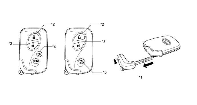
Text in Illustration *1 Mechanical Key *2 Lock Button *3 Unlock Button *4 Power Back Door Button (Models with power back door system and panic control) *5 Power Back Door Button (Models with power back door system and without panic control) - -
-
-
Power Switch
-
The power switch consists of a momentary type switch, indicator light (amber and green color LEDs), illumination, antenna coil, and transponder key amplifier.
-
The driver can determine the present power source* and check whether the hybrid control system can start or not in accordance with the illumination state of the indicator light.
-
When the power management control ECU detects an abnormality with the entry and start system, it makes the amber indicator light flash. If the hybrid control system is stopped in this state, it might not be possible to restart it.
*: In this chapter, the expression "power source" has been used in some locations to allow precise explanations. The power source condition is also expressed using conventional expressions such as "power switch off", "power switch on (ACC)" and "power switch on (IG)".
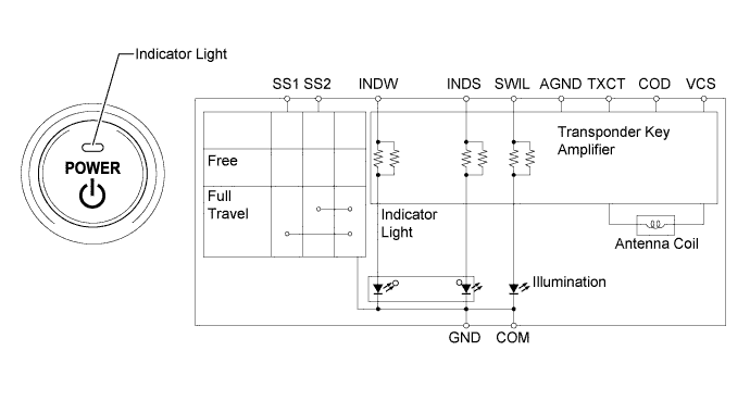
Power Source Condition Indicator Light Condition Brake pedal not depressed Brake pedal depressed with shift lever in P or N Off OFF ON (Green) On (ACC), On (IG) ON (Amber) ON (Green) READY OFF OFF Steering Lock not Unlocked Flashes (Green) for 15 seconds Flashes (Green) for 15 seconds Entry and Start System Malfunction Flashes (Amber) for 15 seconds Flashes (Amber) for 15 seconds
-
-
Power Management Control ECU
-
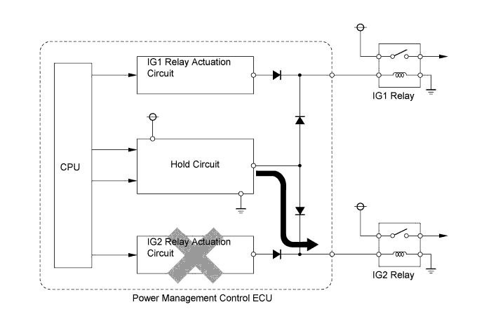
Power management control ECU consists of the IG1 relay and IG2 relay actuation circuits, CPU, and hold circuit.
-
The hold circuit is installed to prevent the power supply to the relays from being cut off when an abnormality occurs in IG1 relay and/or IG2 relay actuation circuits while driving.
Tech Tips
The power management control ECU constantly stores the present power source state in its memory. Therefore, if the power to power management control ECU is interrupted due to the removal of the battery, the power management control ECU restores the power source after the battery is reconnected.
For this reason, if the battery is removed when the power source is in a mode other than off, the power will be restored to the vehicle at the same time the power is restored to power management control ECU (by reconnecting the battery).
Therefore, before removing the battery, be sure to turn the power source off.
-
-
-
DIAGNOSIS
-
Start Function
-
The power management control ECU and certification ECU (smart key ECU assembly) can detect malfunctions in the entry and start system when the power source is on (IG).
-
When the ECUs detect a malfunction, the amber indicator light of the power switch flashes to warn the driver. At the same time, the ECUs store a 5-digit Diagnostic Trouble Code (DTC) in their memories.
-
The indicator light warning continues for 15 seconds even after the power switch is turned to off.
-
The 5-digit DTCs can be read after connecting the intelligent tester to the DLC3.
-
The entry and start system may not operate successfully if a malfunction occurs.
-
-