ACTIVE STABILIZER SUSPENSION SYSTEM DETAILS
-
FUNCTION OF MAIN COMPONENTS
-
The main components in the active stabilizer suspension system have the following functions:
Components Function Front and Rear Active Stabilizer Control ECU Assembly
-
Provided to control each active stabilizer control actuator assembly (1 ECU for the front and 1 for the rear).
-
Calculates the target twist angle of the stabilizer bar and actuates the front and rear active stabilizer control actuator assembly in accordance with signals received from the sensors.
-
The front and rear active stabilizer control ECUs communicate to keep an optimal balance of the twist angles of the front and rear active stabilizer control actuator assemblies.
-
Receives speed sensor signals via the skid control ECU. When the wheel speed sensor output frequency increases and decreases frequently, the active stabilizer control ECU assembly judges that the vehicle is being driven on a rough road.
-
Sends power to the 3 phases of the brushless motor in the active stabilizer control actuator assemblies based on the feedback from the rotational angle sensor.
Front and Rear Active Stabilizer Control Actuator Assembly
- Rotational Angle Sensor
-
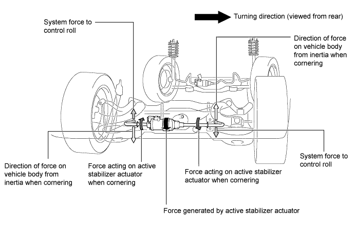
Twists the stabilizer bar in accordance with the signals received from the active stabilizer control ECU assembly, in order to control the roll angle of the vehicle.
-
Detects the rotational position of the actuator motor rotor and sends it back to the active stabilizer control ECU assembly.
Power Steering Converter Assembly (DC-DC Converter) Drops the supply voltage (288 V) from the HV battery to the active stabilizer actuator operation voltage (46 V). HV Battery Supplies operation voltage for the active stabilizer actuators via the power steering converter assembly (DC-DC converter). Steering Angle Sensor Detects the steering angle of the steering wheel and transmits them to the front and rear active stabilizer control ECU assembly. Yawrate Sensor
-
Detects the vehicle's longitudinal and lateral acceleration and deceleration.
-
Detects the vehicle's yaw rate.
Skid Control ECU Transmits the vehicle speed signal provided by the speed sensor to the front and rear active stabilizer control ECU assemblies. Combination Meter Assembly Multi-information Display Indicates "Check Active Stabiliser Suspension System" to inform the driver of a malfunction in the system. Master Warning Light Illuminates to warn the driver of a malfunction in the system. Buzzer Sounds to warn the driver of a malfunction in the system. -
-
-
OPERATING CONDITION
-
The operating conditions of the active stabilizer system are as follows:
Operating Conditions - Vehicle driven at 15km/h or more
- Vehicle moving forward
- Vehicle driven on a smooth road
Non-operating Conditions - Vehicle driven at less than 15 km/h
- Vehicle moving backward
- Vehicle driven on a rough road
- Active stabilizer suspension system malfunctioning
-
-
SYSTEM CONTROL
-
The active stabilizer suspension system controls the vehicle roll angle based on the signals from the steering angle sensor, yawrate sensor and skid control ECU (vehicle speed signals).
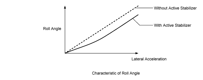
-
The active stabilizer control ECU assembly calculates the target roll angle based on lateral acceleration estimated by the steering angle and vehicle speed, and also based on lateral acceleration measured by the yawrate sensor in order to operate the active stabilizer control actuator assemblies.
-
-
CONSTRUCTION
-
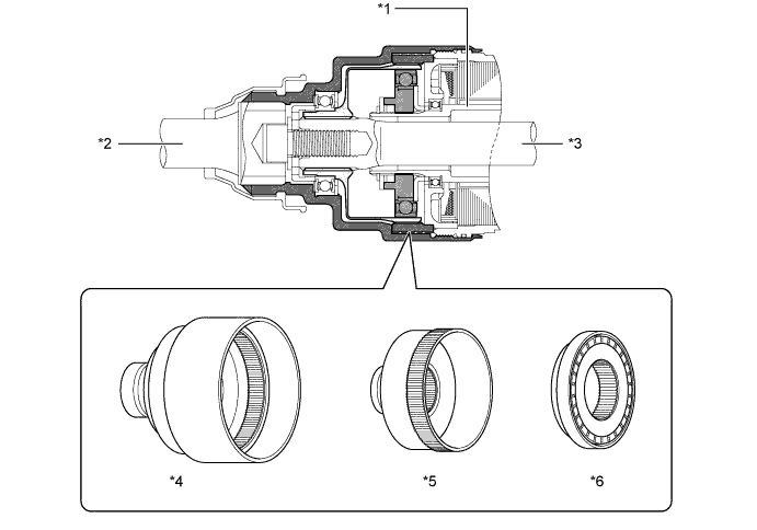
Front and Rear Active Stabilizer Control Actuator Assembly
-
The active stabilizer control actuator assembly which are located axially along the front and rear stabilizer bars, consist of components such as a motor and a reduction mechanism.
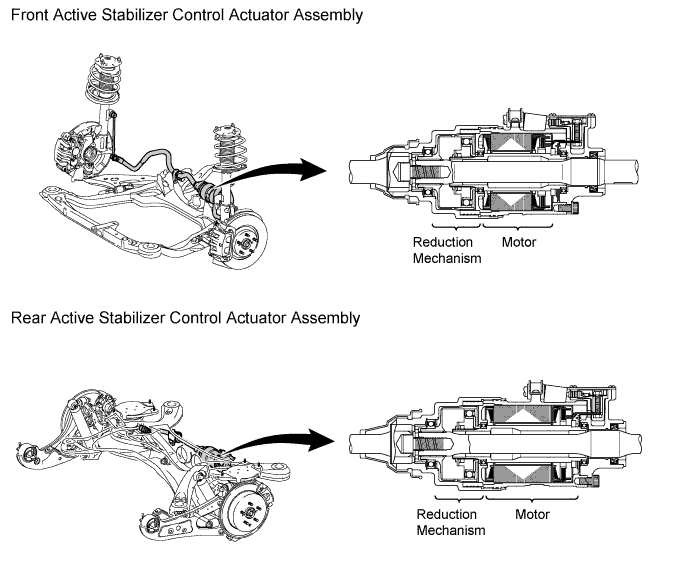
-
A compact, high power output, and low noise brushless type motor is used.
-
The motor shaft is coupled to the wave generator, and the motor housing is coupled to the circular gear.
-
The rotational angle sensor detects the rotational angle of the motor shaft and sends a signal to the active stabilizer control ECU assembly.
-
If a system malfunction occurs, the built-in motor short relay short circuits the motor terminals and virtually locks the active stabilizer actuator.
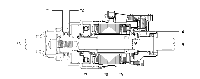
Text in Illustration *1 Circular Gear *2 Flexible Gear *3 RH Stabilizer Bar *4 Rotational Angle Sensor *5 LH Stabilizer Bar *6 Motor Short Relay Portion *7 Wave Generator *8 Motor Housing *9 Motor Shaft - - -
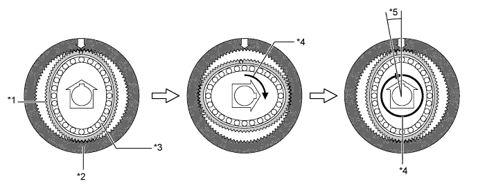
The construction of the wave generator, flexible gear and circular gear is as follows:
Item Construction Wave Generator
-
Consists of an oval-shaped cam, a ball bearing that is fitted around the cam.
-
Coupled to the motor shaft of the motor, rotates inside the flexible gear.
Flexible Gear
-
Consists of an elastic metal outer circumference that has 400 teeth and the spline coupled to the RH stabilizer bar.
-
Located on the outside of the wave generator, it meshes with the circular gear while undergoing elastic deformation from the rotational movement of the wave generator.
Circular Gear
-
Consists of a housing inner circumference that has 402 teeth and the spline coupled to the LH stabilizer bar.
-
Located on the outside of the flexible gear, it meshes with the major axis of the flexible gear via the rotational movement of the wave generator.
Text in Illustration *1 Motor Shaft *2 RH Stabilizer Bar *3 LH Stabilizer Bar *4 Circular Gear *5 Flexible Gear *6 Wave Generator -
-
-
Power Steering Converter Assembly (DC-DC Converter)
-
Upon receiving the request signals from the active stabilizer control ECU assembly, the power steering converter assembly (DC-DC Converter) drops the HV battery voltage from DC 288 V to DC 46 V to supply electrical power to each active stabilizer control ECU assembly.
-
Each active stabilizer control ECU assembly uses the converted electrical power to activate its respective active stabilizer control actuator. As a result, the active stabilizer control actuator assemblies can generate a quick response despite being compact.
-
-
-
OPERATION
-
Front and Rear Active Stabilizer Control Actuator Assembly
-
The active stabilizer control ECU assembly determines the operation amount of the active stabilizer control actuator assembly based on signals from various sensors, and sends power to operate the actuator.
-
If the motor in the actuator is operated by the power from the active stabilizer control ECU assembly, the wave generator rotates.
-
The engagement position of the flexible gear with the circular gear moves as its shape is being changed by the wave generator.
-
After the motor makes 1 turn, the flexible gear will have shifted in the opposite direction of motor rotation because the number of the flexible gear teeth and the number of circular gear teeth are different.
-
The flexible gear is connected to the right side stabilizer bar and the circular gear to the left side stabilizer bar, so that as the motor operates, a position difference is generated between the left and right side stabilizer bars.
-
If the stabilizer bar is adjusted with an appropriate amount of motor operation, the roll angle when cornering will be controlled.
Text in Illustration *1 Flexible Gear *2 Circular Gear *3 Wave Generator *4 Motor Rotation *5 Position difference generated between the flexible gear and circular gear - -
-
-
-
FAIL-SAFE
-
If either active stabilizer control ECU assembly detects a malfunction in the system, the master warning light is illuminated, the warning message "Check Active Stabilizer Suspension System" is indicated on the multi-information display, and a buzzer is sounded to inform the driver, and system control is stopped.
-
If a system malfunction occurs, the fail-safe function shorts the terminals of the motors of the active stabilizer actuators. This generates a braking force that virtually locks the RH and LH stabilizer bars, thus ensuring the same function as a conventional stabilizer bar.
-
-
DIAGNOSIS
-
If a system malfunction occurs, Diagnostic Trouble Codes (DTCs) are stored in each memory of the front and rear active stabilizer control ECU assembly.
-
For details, refer to the Repair Manual.
-