REAR DRIVE SYSTEM DETAILS
-
CONSTRUCTION
-
Drive Unit Case and Cover
-
The drive unit case and cover are made of aluminum.
-
The shape of the case and the shape of the ribs have been optimized to achieve a highly rigid and lightweight construction. Furthermore, cooling fins have been provided on top of the drive unit case to improve cooling performance.
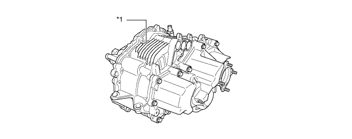
Text in Illustration *1 Cooling Fins
-
-
Motive Force Transmission Path
-
The Q211 rear drive unit (rear traction motor with transaxle assembly) transfers the motive force of MGR to the counter drive gear, counter driven gear, differential drive pinion gear, differential ring gear, and differential gear unit, in order to drive the rear wheels.
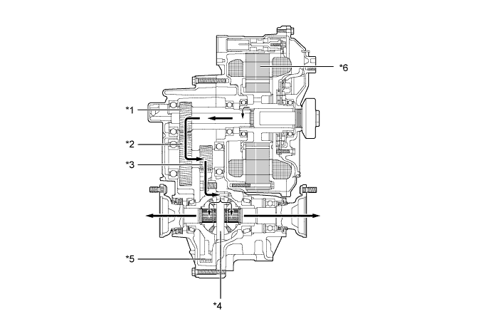
Text in Illustration *1 Counter Drive Gear *2 Counter Driven Gear *3 Differential Drive Pinion Gear *4 Differential Gear Unit *5 Differential Ring Gear *6 Motor Generator Rear (MGR)
-
-
Lubrication Mechanism
-
The Q211 rear drive unit (rear traction motor with transaxle assembly) is lubricated by ATF slung up by the differential ring gear. A fluid catch tank is used in this drive unit in order to supply oil in a stable manner. The fluid catch tank temporarily stores the ATF that is slung up, and supplies ATF in a stable manner to the different parts of the gear train.
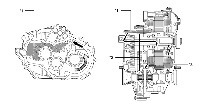
Text in Illustration *1 Fluid Catch Tank *2 Fluid slung up by ring gear *3 MGR lubricated with ATF 
Fluid Flow 
Differential Ring Gear Rotation Direction - -
-
-