HYBRID TRANSAXLE SYSTEM DETAILS
-
SYSTEM CONTROL
-
Sequential Shiftmatic System
-
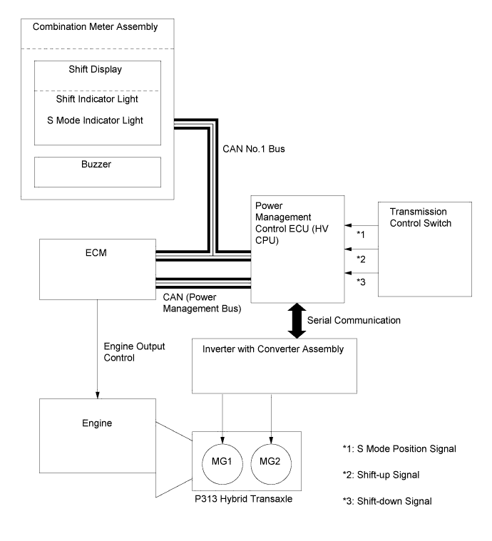
The sequential shiftmatic system uses the power management control ECU (HV CPU) to control the engine, MG1 and MG2 based on signals received from the transmission control switch. The signals are output in accordance with the shift lever movement. Thus the driver can select the desired level of engine braking force and acceleration response.
-
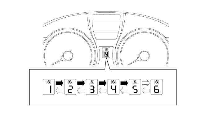
When the driver moves the shift lever to S to select S mode, the engine braking range will appear on the shift display of the combination meter assembly.
-
-
-
CONSTRUCTION
-
Automatic Transmission Fluid (ATF) WS
-
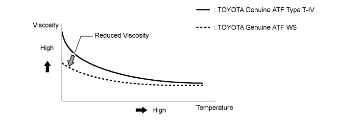
TOYOTA genuine ATF WS is used to reduce the resistance of the ATF and improve the fuel economy by reducing its viscosity in the practical operating temperature range. At higher-fluid temperatures, the viscosity is the same as that of TOYOTA genuine ATF Type T-IV, to ensure the durability of the automatic transmission.
-
There is no interchangeability between the TOYOTA genuine ATF WS and other types of ATF (D-II, D-III or TOYOTA genuine ATF Type T-IV).
-
-
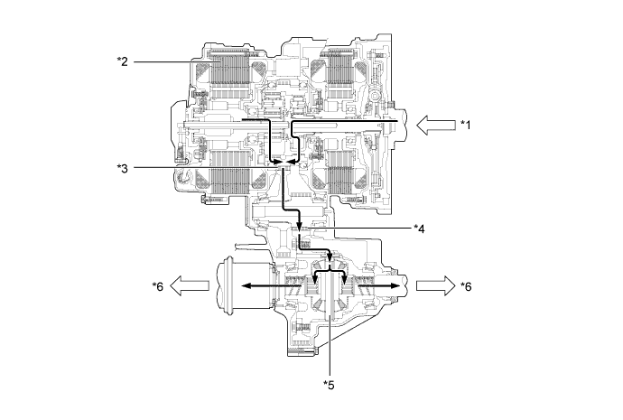
P313 Hybrid Transaxle (Hybrid Vehicle Transaxle Assembly)
-
The P313 hybrid transaxle has a 3-shaft configuration.
-
The transmission damper, compound gear unit, counter drive gear, Motor Generator 1 (MG1), Motor Generator 2 (MG2), and oil pump are mounted either coaxially or on the input shaft.
-
The counter driven gear and final drive gear are part of the 2nd shaft.
-
The final driven gear and differential gear unit make up the 3rd shaft.
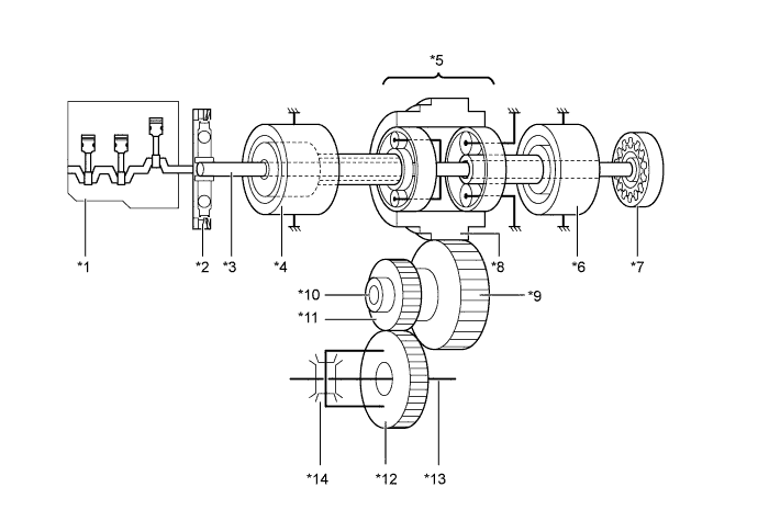
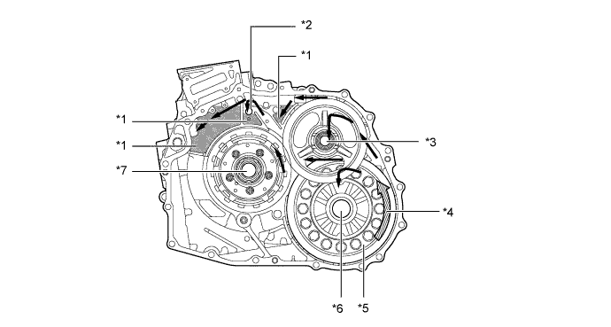
Text in Illustration *1 Engine *2 Transmission Damper *3 Input Shaft *4 Motor Generator 1 (MG1) *5 Compound Gear Unit *6 Motor Generator 2 (MG2) *7 Oil Pump *8 Counter Drive Gear *9 Counter Driven Gear *10 2nd Shaft *11 Final Drive Gear *12 Final Driven Gear *13 3rd Shaft *14 Differential Gear Unit
-
-
Compound Gear Unit
-
The compound gear unit consists of the motor speed reduction planetary gear unit and the power split planetary gear unit.
-
The motor speed reduction planetary gear unit, whose purpose is to reduce MG2 speed, is used to enable the high-speed, high-output MG2 to adapt optimally to the power split planetary gear unit.
-
The power split planetary gear unit splits the motive force of the engine two ways: one to drive the wheels, and the other to drive MG1, so that MG1 can function as a generator.
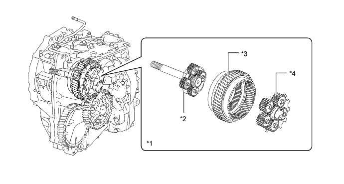
Text in Illustration *1 Compound Gear Unit *2 Power Split Planetary Gear *3 Counter Drive Gear *4 Motor Speed Reduction Planetary Gear 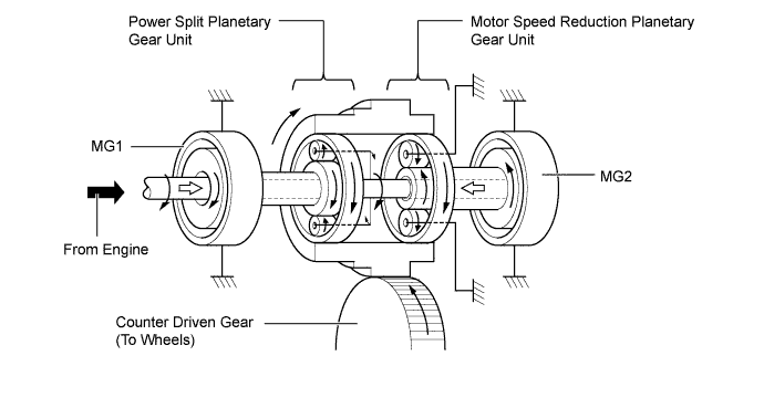
-
The connection of the sun gear, ring gear and carrier of each planetary gear unit is as shown below.
Planetary Gear Connection Power Split Planetary Gear Unit Sun Gear Motor Generator 1 (MG1) Ring Gear Compound Gear (Output) Carrier Engine Output Shaft Motor Speed Reduction Planetary Gear Unit Sun Gear Motor Generator 2 (MG2) Ring Gear Compound Gear (Output) Carrier Fixed
-
-
Transmission Damper
-
A transmission damper with low-twist characteristics that utilizes coil springs is used in order to absorb the torque fluctuation in the drive force of the engine.
-
The torque limiter uses a dry-type, single-plate friction material. Through the use of these parts, a damper construction that excels in absorbing the vibrations of the engine motive force is achieved.
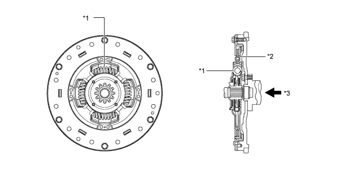
Text in Illustration *1 Coil Spring *2 Torque Limiter *3 Drive Force from Engine - -
-
-
Lubrication and Cooling System
-
The lubrication and cooling system has an air-cooled type oil cooler assembly.
-
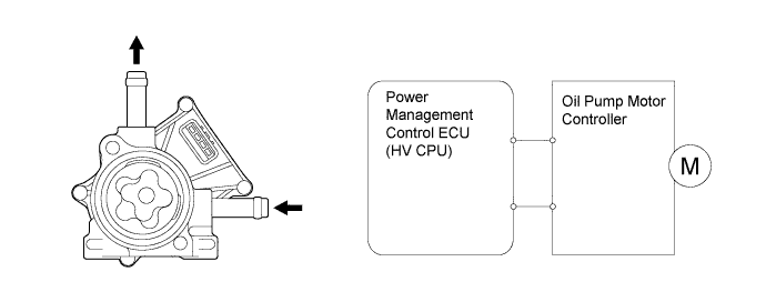
The P313 hybrid transaxle (hybrid vehicle transaxle assembly) is lubricated by a trochoid type oil pump placed on the main shaft and oil pump with motor assembly.
-
The oil pump with motor assembly is controlled by the power management control ECU (HV CPU). The power management control ECU (HV CPU) drives the oil pump with motor assembly based on the vehicle speed signal and the temperature sensor signals of Motor Generator 1 (MG1) and Motor Generator 2 (MG2).
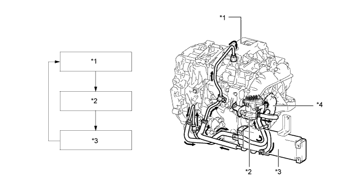
Text in Illustration *1 P313 Hybrid Transaxle (Hybrid Vehicle Transaxle Assembly) *2 Oil Pump with Motor Assembly *3 Oil Cooler Assembly *4 Oil Pump 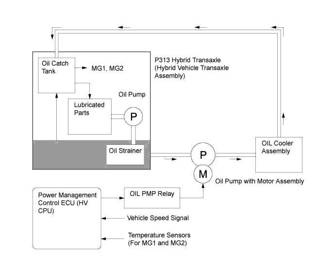
-
The lubrication method used for this transaxle has a final drive gear which employs an oil sling type lubrication method via oil catch tanks. This construction minimizes the drive torque of the oil pump, which reduces the drive loss.
-
The oil catch tanks temporarily store the fluid that is slung up, and they supply oil to the different parts of the gear train. Oil holes are provided in the oil catch tanks in order to efficiently supply oil to MG1 and MG2.
Text in Illustration *1 Oil Catch Tank *2 Oil Hole *3 2nd Shaft *4 Final Gear Rotational Direction *5 Final Gear *6 3rd Shaft *7 Main Shaft - -
-
-
Oil Pump with Motor Assembly
-
The oil pump with motor assembly consists of a trochoid type oil pump, motor, and motor drive.
-
The trochoid type oil pump is driven by the motor.
-
The motor is operated using duty control performed by the motor driver based on instructions from the power management control ECU (HV CPU).
-
-
Shift Control System
-
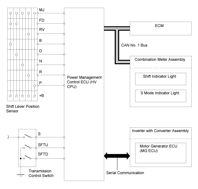
The shift control system consists of a shift lever, transmission control cable assembly, shift lever position sensor, transmission control switch, parking lock mechanism, and power management control ECU (HV CPU).
-
The shift lever used is a 5-position (P, R, N, D, and S) gate type lever. The gate type shift lever operates on the single-shift operation principle (fore-aft and side-to-side). Therefore, it does not require the use of a shift lever button, which is used on a straight type shift lever. Therefore, it excels in ease of use.
-
The power management control ECU (HV CPU) optimally combines the operation of the engine, MG1, MG2, and MGR in order to produce the respective shift positions.
-
-
Shift Lever Position Sensor and Transmission Control Switch
-
The shift lever position sensor sends the P, R, N and D position signals to the power management control ECU (HV CPU).
-
The power management control ECU (HV CPU) transmits signals to the combination meter assembly for the shift indicator lights (P, R, N, and D) in response to the signals received from the sensor.
-
The transmission control switch is installed inside the shift lever assembly to inform the power management control ECU (HV CPU) of the shift lever position.
-
-
Parking Lock Mechanism
-
The parking lock mechanism consists of a parking lock pawl and a parking gear which is integrated with the compound gear.
-
When the driver moves the shift lever to P, the parking lock pawl engages with the parking lock gear.
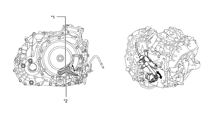
Text in Illustration *1 Parking Lock Gear *2 Parking Lock Pawl
-
-
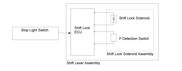
Shift Lock System
-
The shift lock system uses the shift lock ECU to control the shift lock function.
-
The shift lock function prevents the shift lever from being moved from P, unless the power switch is on (IG or READY) and the brake pedal is depressed.
-
A concealed shift lock override button allows for a manual override of the shift lock system if this is necessary.
-
-
-
OPERATION
-
Motive Force Transmission Path
-
The motive force created by the engine and Motor Generator 2 (MG2) is transmitted by the counter drive gear of the compound gear unit, the counter driven gear, the final drive gear, and then the differential gear unit, in order to drive the front wheels.
Text in Illustration *1 From Engine *2 Motor Generator 2 (MG2) *3 Counter Driven Gear *4 Final Gear *5 Differential Gear Unit *6 To Wheels
-
-
Sequential Shiftmatic System
-
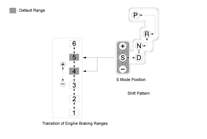
When the driver selects S mode by moving the shift lever, an engine braking range to 4th or 5th is automatically selected. By moving the shift lever from S to "+" or "-", the driver can select an engine brake range from 1 to 6.
-
By holding the shift lever in "+" for 1 second or longer, the engine brake range automatically changes from any range to 6. The lower the engine brake range, the greater the engine braking force will be.
-
Upon receiving an engine braking range down request issued by the driver through the operation of the shift lever, this system limits the switching of the engine braking range if the vehicle is operating at a speed that is higher than the limit speed, and sounds a buzzer to alert the driver.
Engine Brake Range Limit Speed* 6th → 5th - 5th → 4th 168 km/h (104 mph) 4th → 3rd 119 km/h (74 mph) 3rd → 2nd 83 km/h (52 mph) 2nd → 1st 49 km/h (30 mph) *: The speeds are provided for reference only.
-
If the vehicle accelerates from engine brake range 1 through 5, the engine brake range goes up automatically to range 5 in accordance with the vehicle speed. At this time, the shift indicator light displayed on the shift display also changes.
Text in Illustration 
Automatic Operation 
Manual Operation
-
-