BRAKE CONTROL SYSTEM DETAILS
-
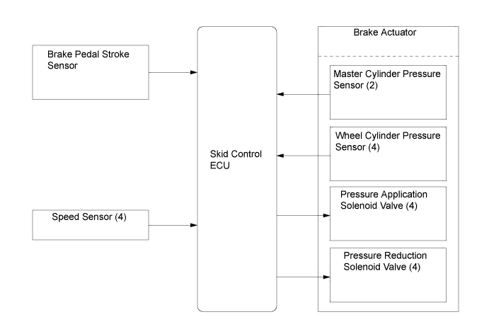
FUNCTION OF MAIN COMPONENTS
Component Function Brake Actuator
-
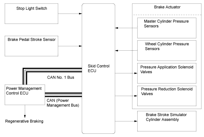
Consists of 2 master cylinder cut solenoid valves, 4 pressure application solenoid valves, and 4 pressure reduction solenoid valves.
-
The master cylinder pressure sensors, the accumulator pressure sensor, the wheel cylinder pressure sensors and the relief valve are installed in the brake actuator.
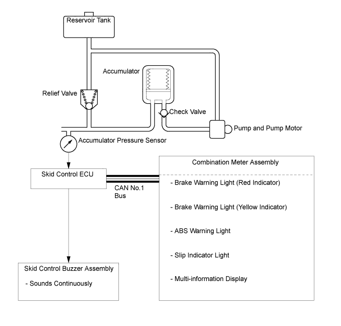
Brake Booster Pump Assembly Accumulator Stores the hydraulic pressure that was generated by the pump. The accumulator is filled with high pressure nitrogen gas. Pump and Pump Motor Draws up the brake fluid from the reservoir tank and provides high hydraulic pressure to the accumulator. Skid Control ECU Monitors the driving conditions of the vehicle in accordance with the signals received from the sensors and through cooperative control with the power management control ECU and power steering ECU assembly calculates the required amount of braking force, and controls the brake actuator. Master Cylinder Sub-assembly
-
Generates hydraulic pressure in accordance with the amount of effort applied to the brake pedal by the driver.
-
When a malfunction occurs in the power supply portion of the brake actuator, the brake master cylinder supplies the fluid pressure (which is generated by brake pedal effort) directly to the wheel cylinders.
Combination Meter Assembly Brake Warning Light Red Indicator:
-
Illuminates to alert the driver that the skid control ECU detects the malfunction in the apportioning of the brake.
-
Illuminates to inform the driver when the parking brake is ON or the brake fluid is low.
Yellow Indicator:
-
Illuminates to alert the driver that a minor malfunction which does not affect the braking force has occurred in the brake system.
ABS Warning Light Illuminates to alert the driver when the skid control ECU detects a malfunction in the ABS or Brake Assist. Slip Indicator Light
-
Blinks to inform the driver when the ABS, TRC, VSC or Hill-start Assist Control operates.
-
Illuminates to alert the driver when the skid control ECU detects a malfunction in the TRC or VSC systems.
VSC OFF Indicator Light Illuminates to inform the driver when VSC OFF mode is selected. Master Warning Light
-
Lights up to alert the driver when the skid control ECU detects a malfunction in the brake control system.
-
Displays a warning message to alert the driver when TRC OFF mode is selected.
Multi-information Display Shows a warning message to alert the driver when the skid control ECU detects a malfunction in the brake control system. Brake Pedal Stroke Sensor Directly detects the extent of the brake pedal stroke operated by the driver. Brake Stroke Simulator Cylinder Assembly Provides a pedal stroke during braking in accordance with the driver's pedal effort. Stroke Simulator Cut Valve Allows the fluid pressure generated by the master cylinder sub-assembly to flow into the brake stroke simulator cylinder assembly while the electronically controlled brake system operates. Stop Light Control Relay Assembly
-
Illuminates the stop lights when Hill-start Assist Control is operating.
-
Blinks the stop lights while emergency stop light control is operating.*3
ECB MTR1 Relay and ECB MTR2 Relay
-
These are 2 types of pump motor relays with different pump actuation speeds.
-
If one relay fails, the other relay operates to actuate the pump.
Skid Control Buzzer Assembly
-
Emits a warning sound to inform the driver when Hill-start Assist Control operation is started or finished.
-
Sounds continuously to inform the driver if there is a hydraulic pressure malfunction or power supply failure.
-
Sounds to inform the driver of a change in brake pedal feeling if the skid control ECU has not learned the conditions of the linear solenoid valves in the brake actuator.
-
Sounds on receiving a signal from the skid control ECU and alerts the driver that the distance between vehicle is short.*1
-
Emits a warning sound to inform the driver during brake control operation (operating dynamic radar cruise control or pre-crash brake).*2
Reservoir Tank Stores the brake fluid. Brake Fluid Level Warning Switch Detects a low brake fluid level. Stop Light Switch Detects brake pedal operation. Parking Brake Switch Detects parking brake operation. VSC OFF Switch Enables the driver to select Normal mode, TRC OFF mode or VSC OFF mode. Hazard Warning Switch*3 Transmits a hazard warning light on/off request to the main body ECU. Yawrate Sensor
-
Detects the vehicle's yaw rate.
-
Detects the vehicle's longitudinal and lateral acceleration and deceleration.
Steering Angle Sensor Detects the steering direction and angle of the steering wheel. Accelerator Pedal Position Sensor Detects the accelerator pedal depression angle. Speed Sensor (4) Detect the wheel speed of each of the 4 wheels. Brake Control Power Supply Assembly
-
An auxiliary power supply to provide stable electrical power to the brake system.
-
When the voltage of the auxiliary battery is low, the brake control power supply assembly supplements the supply of power to the brake system by providing the electric charge that is stored in the unit.
Power Management Control ECU
-
Actuates regenerative braking upon receiving a signal from the skid control ECU.
-
Sends the actual regenerative braking control value to the skid control ECU.
-
Controls the drive force based on an output control request signal received from the skid control ECU while the VSC function or TRC function is operating.
ECM Control the engine output based on an output control request signal received from the power management control ECU Power Steering ECU Assembly The power steering ECU assembly performs cooperative control with the skid control ECU, in order to control the steering assist force in accordance with information received from the skid control ECU. Main Body ECU (Multiplex Network Body ECU)
-
Transmits the parking brake signal to the skid control ECU.
-
Detects the hazard warning switch on/off signal and outputs it to the skid control ECU via CAN communication.*3
*1: Models with dynamic radar cruise control
*2: Models with pre-crash brake
*3: Models for Europe
-
-
OPERATING CONDITION
-
Emergency Brake Signal
-
Emergency brake signal operating conditions are as shown in the following table.
A) Activating Conditions When all of the following conditions are met, the emergency brake signal starts operating:
-
Vehicle speed is over 55 km/h (35 mph).
-
Driver is depressing the brake pedal.
-
Emergency braking is detected from the vehicle deceleration.
B) Deactivating Conditions When any of the following conditions is met, the emergency brake signal stops operating:
-
Driver has released the brake pedal.
-
Emergency braking is no longer detected from the vehicle deceleration.
-
Driver has pressed the hazard warning switch.
-
-
-
-
SYSTEM CONTROL
-
Table of System Control
-
The brake control system has the following system/functions:
Components Function Electronically Controlled Brake System The electronically controlled brake system detects the amount that the brake pedal is depressed based on signals from the brake pedal stroke sensor. The system uses the skid control ECU to adjust the pressure supplied from the hydraulic pressure source for each wheel, generating optimal braking force. Regenerative Braking Cooperative Control This control performs cooperative control with regenerative braking that is specific to hybrid vehicles to efficiently charge the HV battery. Vehicle Dynamics Integrated Management (VDIM) VDIM integrates LEXUS Hybrid Drive brake control (ABS with EBD, Brake Assist, TRC, VSC and Hill-start Assist Control) and steering assist control (EPS) to enhance active safety when accelerating, turning and stopping. Steering Cooperative Control Performs cooperative control with the power steering ECU in order to provide steering torque assist in accordance with present vehicle dynamics. Anti-lock Brake System (ABS) The ABS helps prevent the wheels from locking when the brakes are applied firmly or when braking on a slippery surface. Electronic Brake Force Distribution (EBD) EBD control utilizes the ABS, realizing proper brake force distribution between the front and rear wheels in accordance with the driving conditions. In addition, when braking while cornering, it also controls the brake force applied to the right and left wheels, helping to stabilize vehicle behavior. Brake Assist The primary purpose of Brake Assist is to provide supplementary brake force to assist a driver who cannot generate a large brake force during emergency braking, thus helping ensure the vehicle's braking performance. Traction Control (TRC) The TRC helps restrain the slippage of the drive wheels if the driver depresses the accelerator pedal excessively when starting off or accelerating on a slippery surface. Limited Slip Differential (LSD) Function The LSD function detects the vehicle's turning condition and wheel slippage. Brake force is then applied to the inner wheels to limit slippage and transmit power to the outer wheels, ensuring acceleration performance while turning. Vehicle Stability Control (VSC) The VSC helps restrain sideways slippage of the vehicle during a strong front wheel skid or strong rear wheel skid, such as may occur while cornering. Hill-start Assist Control The Hill-start Assist Control generates 4 wheel hydraulic pressure when the brake pedal is further depressed while the vehicle is stationary in order to prevent the vehicle from moving backward. Emergency Brake Signal* In the case of emergency braking, the emergency brake signal flashes the stoplights to alert the drivers in following vehicles. *: Models for Europe
-
-
Steering Cooperative Control
-
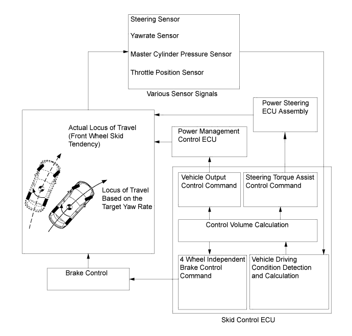
Steering cooperative control performs coordinated control using both VSC and EPS. By integrating these active safety functions, excellent driving stability and maneuverability are secured.
-
If the vehicle loses stability due to wheel slippage, this function performs brake control by applying brake pressure to each individual wheel while at the same time, the EPS provides steering torque assist control to facilitate the driver's steering maneuver.
-
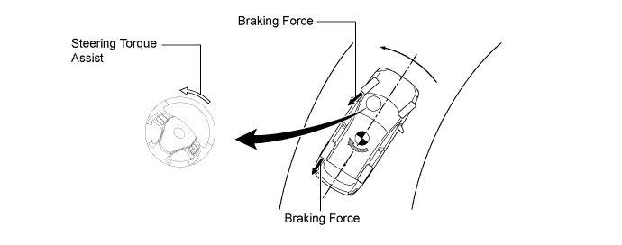
When braking on a split friction road, the vehicle tends to deflect toward the higher friction side due to the difference between the brake force on the left and right sides. In this state, the power steering ECU receives command signals from the skid control ECU. Based on these signals, the power steering ECU operates the EPS motor to reduce the effect of this brake force difference on either side, assisting the driver in making corrective steering operations.
-
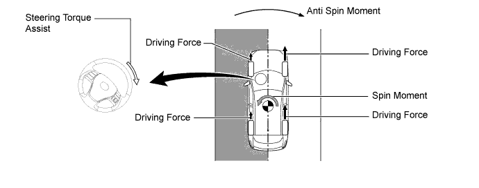
When accelerating on a split friction road, the vehicle tends to deflect toward lower friction side due to the drive force difference between the left and right sides. In this state, the skid control ECU performs brake control of the drive wheel on the low friction side (TRC function) and transmits command signals to the power steering ECU. Based on these signals, the power steering ECU operates the EPS motor to reduce the effect of this drive force difference on either side, assisting the driver in making corrective steering operations. As a result, ideal drive force control and vehicle stability is ensured.
-
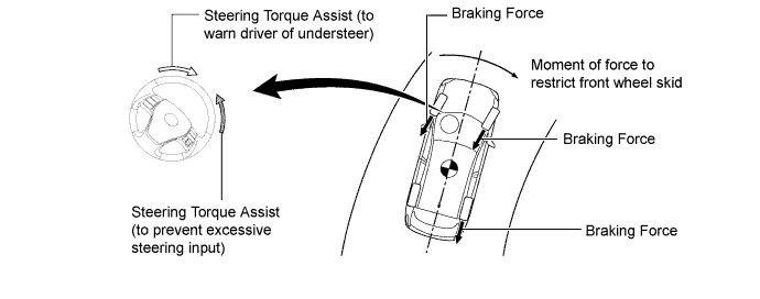
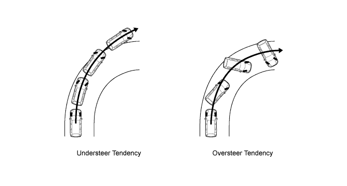
When under steer (front wheel skid) is detected, engine output is limited and brake control is performed based on the amount of understeer tendency. Accordingly, a moment of force is generated in the vehicle turning direction to limit the understeer tendency.
-
Steering torque assist is also provided to warn the driver of understeer.
-
If the driver turns the steering wheel excessively, steering torque assist is provided to prevent excessive steering input.
-
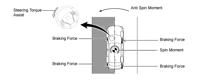
When oversteer (rear wheel skid) is detected, brake force is applied to mainly the outer wheels based to the amount of oversteer tendency. Accordingly, an anti-spin moment is generated to limit the oversteer tendency.
-
In this state, the power steering ECU receives command signals from the skid control ECU. Based on these signals, the power steering ECU operates the EPS motor to compensate for the oversteer tendency, assisting the driver in making corrective steering operations.
-
-
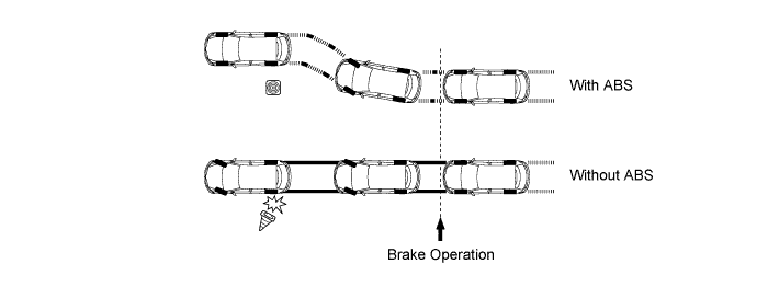
Anti-lock Brake System (ABS)
-
The ABS prevents the wheels from locking during sudden braking or braking on a slippery surface. This provides ideal brake force when the vehicle slips, thus ensuring vehicle stability and excellent braking performance.
-
-
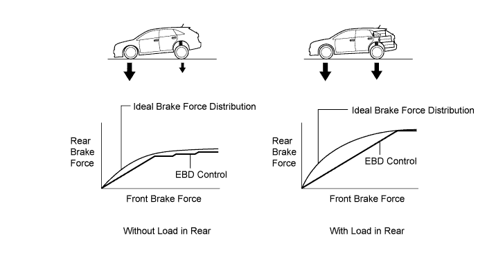
Electronic Brake Force Distribution (EBD)
-
The EBD control distributes the braking force in accordance with the vehicle's driving conditions. The skid control ECU electrically controls the control solenoid valves to distribute the braking force.
-
This function controls the brake force acting on the rear wheels in accordance with changes in the vehicle condition such as load factors or deceleration in order to ensure excellent braking performance.
-
When braking while cornering, this function controls the brake force acting on each individual wheel in accordance with present vehicle behavior. This ensures vehicle stability and excellent braking performance.
-
-
Brake Assist
-
Brake Assist, in combination with ABS, helps ensure the vehicle's brake performance.
-
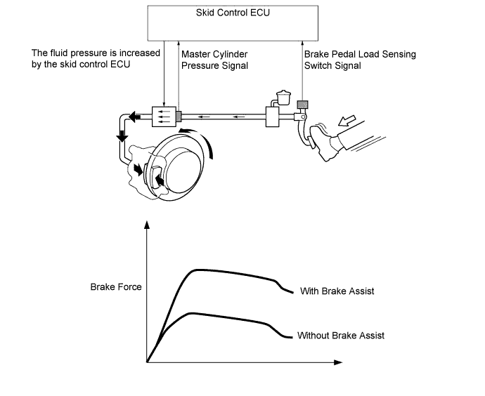
Brake Assist interprets a quick push of the brake pedal as emergency braking and supplements the brake power applied if the driver has not stepped hard enough on the brake pedal. In emergencies, drivers, especially inexperienced ones, often panic and do not apply sufficient pressure to the brake pedal.
-
A key feature of Brake Assist is that the timing and the degree of braking assistance are designed to help ensure that the driver does not discern anything unusual about the braking operation. When the driver intentionally eases up on the brake pedal, the system reduces the amount of assistance it provides.
-
Based on the signals from the master cylinder pressure sensors and brake pedal stroke sensor, the skid control ECU calculates the speed and the amount of brake pedal application and then determines the intention of the driver to perform emergency braking. If the skid control ECU determines that the driver intends emergency braking, the system activates the brake actuator to increase the brake fluid pressure, which increases the braking force.
-
-
Traction Control (TRC)
-
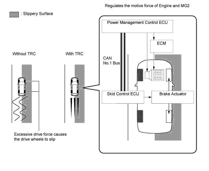
If the driver presses the accelerator pedal aggressively when starting off or when accelerating on a slippery surface, the drive wheels could slip due to the excessive amount of torque that is generated. By applying hydraulic brake control to the drive wheels and regulating the throttle to control the engine output, TRC helps minimize the slippage of the drive wheels, thus generating the drive force that is appropriate for the road surface conditions.
-
For example, a comparison may be made between two vehicles, one with the TRC function and the other without. If the driver of each vehicle operates the accelerator pedal in a rough manner while driving over a surface with different surface friction characteristics, drive wheels on the slippery surface could slip as illustrated. As a result, the vehicle could become unstable.
-
However, when the vehicle is equipped with the TRC function, the skid control ECU determines the state of the vehicle and operates the brake actuator in order to apply the brake of the slipping drive wheel. Furthermore, the power management control ECU receives the signals from the skid control ECU and regulates the throttle in order to control the engine output. Thus, this function can constantly maintain a stable vehicle posture.
-
-
Limited Slip Differential (LSD) Function
-
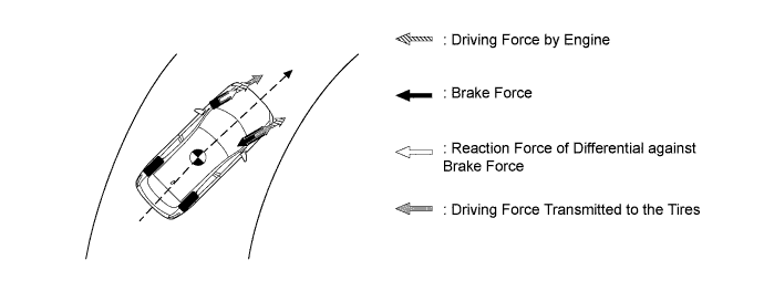
When the vehicle accelerates around a turn, the load shifts to the outside of the turn. This hinders the transfer of drive force from the inner wheels to the road surface, allowing the inside wheels to spin.
-
Upon detecting a turning condition and wheelspin, the LSD function applies the brake to the inner drive wheel. This suppresses the spinning, transfers drive force to the outer wheel, and thus realizes the intended acceleration of the driver.
-
When the engine output is restricted on muddy roads and in deep snow, etc. and a drop occurs in escape performance, engine output control can be stopped by pressing the VSC OFF switch, and departure performance can be ensured.
-
-
Vehicle Stability Control (VSC)
-
The following 2 examples can be considered as circumstances in which the tires exceed their lateral grip limit. VSC is designed to help control the vehicle behavior by controlling the engine output and the brakes at each wheel when the vehicle is subject to one of the conditions indicated below.
-
To determine the condition of the vehicle, sensors detect the steering angle, vehicle speed, vehicle's yaw rate, and the vehicle's lateral acceleration, which are then calculated by the skid control ECU.
-
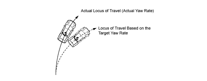
Whether or not the vehicle is experiencing understeer is determined by the difference between the target yaw rate and the vehicle's actual yaw rate. When the vehicle's actual yaw rate is smaller than the target yaw rate (a target yaw rate is determined based on the vehicle speed and steering angle) that should be generated when the driver operates the steering wheel, it means the vehicle is making a turn at a greater angle than the target locus of travel. Thus, the skid control ECU determines that there is a large understeer tendency.
-
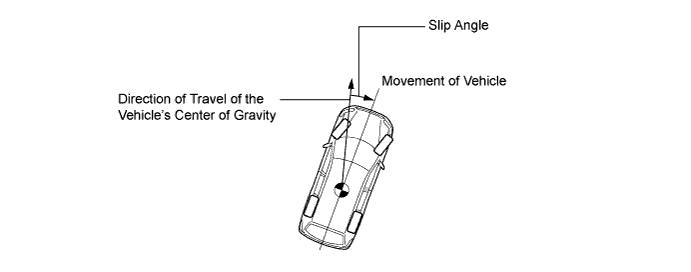
Whether or not the vehicle is experiencing oversteer is determined by the values of the vehicle's slip angle and the vehicle's slip angular velocity (time-dependent changes in the vehicle's slip angle). When the vehicle's slip angle is large, and the slip angular velocity is also large, the skid control ECU determines that the vehicle has a large oversteer tendency.
-
When the skid control ECU determines that the vehicle exhibits a tendency to experience a front wheel skid or a rear wheel skid, it decreases the engine output and applies the brakes to each wheel individually to control the vehicle's yaw moment. The basic operation of the VSC is described below. However, the control method differs depending on the vehicle's characteristics and driving conditions.
-
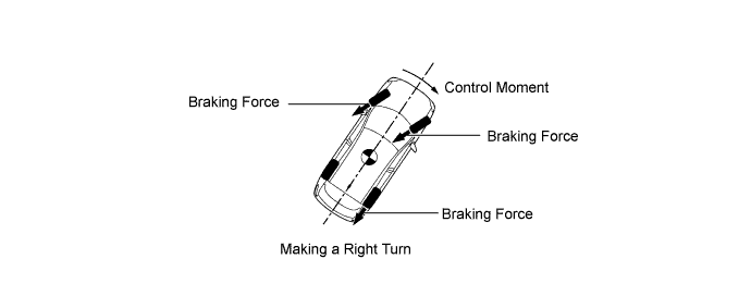
When the skid control ECU determines that there is a large front wheel skid tendency, it takes countermeasures in accordance with the extent of that tendency. The skid control ECU controls the engine output and applies the brakes of the front wheels and rear wheel of the inner circle of the turn in order to help restrain the front wheel skid tendency.
-
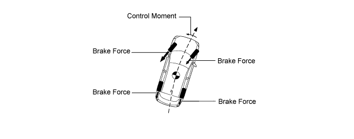
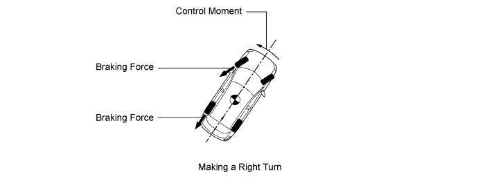
When the skid control ECU determines that there is a large rear wheel skid tendency, it takes countermeasures in accordance with the extent of that tendency. It applies the brakes of the front wheel of the outer circle of the turn, and generates an outward moment of inertia in the vehicle, in order to restrain the rear wheel skid tendency. Along with the reduction in the vehicle speed caused by the braking force, excellent vehicle stability is ensured.
-
-
Hill-start Assist Control Function
-
When the vehicle starts off on a steep or slippery hill, the vehicle could descend backward while the driver switches from the brake pedal to the accelerator pedal, thus making it difficult for the vehicle to start off. To prevent this from occurring, Hill-start Assist Control temporarily (for approximately a few seconds) applies the brakes to all the wheels in order to reduce the backward speed of the vehicle.
-
Without Hill-start Assist Control, the driver must quickly and precisely switch from the brake pedal to the accelerator pedal. With Hill-start Assist Control however, the driver can start off easily and operate the pedal in a relaxed manner because Hill-start Assist Control prevents the vehicle from descending.
-
-
Emergency Brake Signal
-
Emergency brake signal automatically flashes all the stop lights in the case of emergency braking in order to reduce the risk of being rear ended by a following vehicle.
-
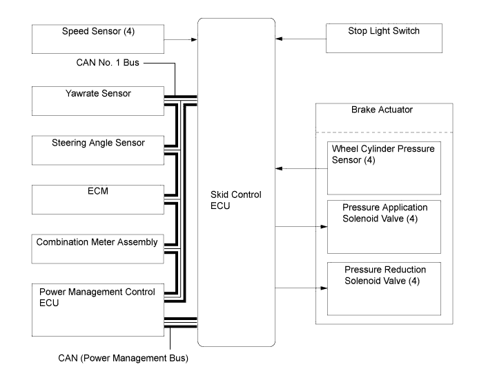
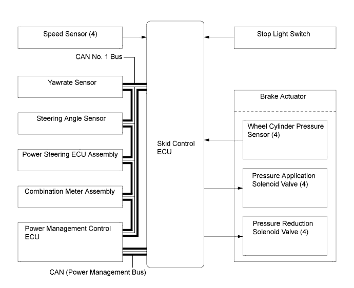
The skid control ECU detects the vehicle condition and braking operation using speed sensors, the yawrate sensor and stop light switch.
-
Based on these various signals, the skid control ECU sends an instruction to the stop light control relay to flash the stop lights if emergency braking is detected.
-
-
-
FUNCTION
-
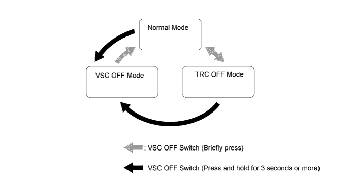
VSC OFF Switch
-
Using the VSC OFF switch can stop the operation of the VSC and TRC functions. This is used to stop engine output control and maintain drive torque when driving on the shoulder or on dirt roads.
-
The VSC OFF switch can select 3 modes (Normal mode, TRC OFF mode, VSC OFF mode).
-
After the power switch is turned off in TRC OFF mode or VSC OFF mode, turning the power switch ON again selects normal mode.
-
The operations of the brake control functions in each mode are as follows:
Item Brake Control Function Multi-information Display VSC OFF Indicator Light TRC VSC Normal Mode Controllable Controllable - - TRC OFF Mode X Controllable TRC OFF message is displayed - VSC OFF Mode X X* TRC OFF message is displayed Illuminates
-
X: Not controllable
-
-: Not displayed or not illuminated
*: Control will be performed during braking or if the yaw rate is excessive.
-
-
-
-
CONSTRUCTION
-
Steering Angle Sensor
-
The steering angle sensor detects the steering direction and angle, and sends this signal to the skid control ECU.

-
-
Yawrate Sensor
-
The yawrate sensor detects the vehicle's yaw rate.
-
The deceleration sensor detects longitudinal acceleration and deceleration.

Text in Illustration *1 Deceleration Sensor *2 Yawrate Sensor Tech Tips
After replacing the yawrate sensor, or skid control ECU, initialization of the yawrate sensor is required. For details, refer to the Repair Manual .
-
-
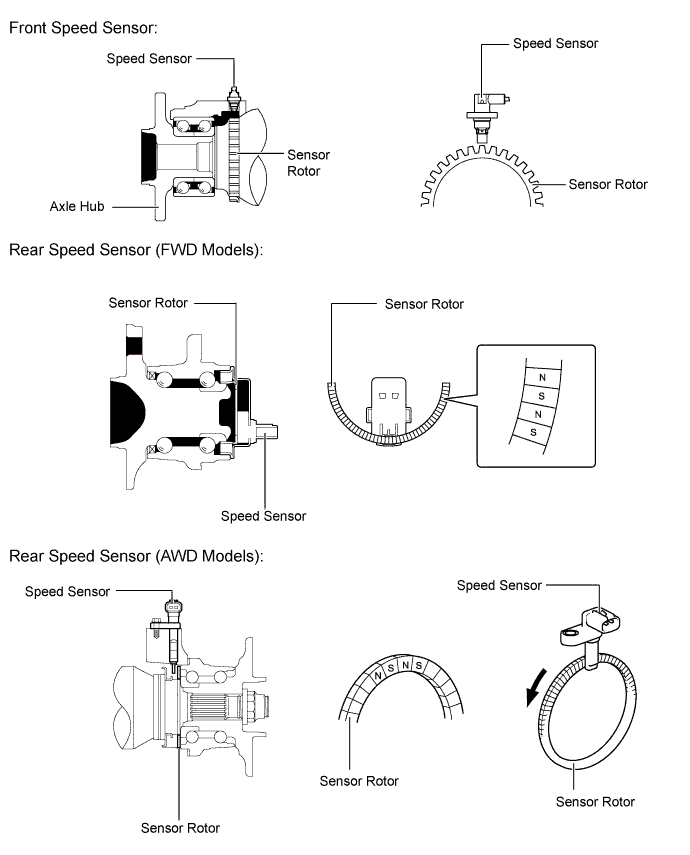
Speed Sensor
-
An active type speed sensor is used. This sensor contains a Hall IC.
-
The magnet type rotor, which consists of N and S poles arranged in a circle, is integrated with the hub bearing inner race.
-
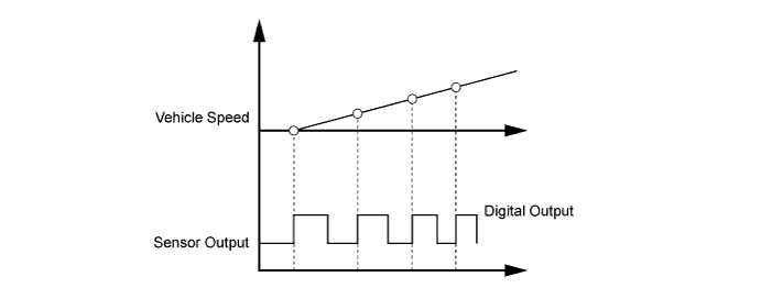
The active type speed sensor use the frequency of output pulses to detect the vehicle speed.
-
Because the sensor outputs digital pulses, it can detect vehicle speeds even when the vehicle is nearly stationary.
-
-
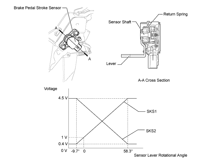
Brake Pedal Stroke Sensor
-
This sensor, which contains a non-contact type semiconductor, detects the extent of the brake pedal stroke and transmits it to the skid control ECU.
Tech Tips
When replacing the brake pedal stroke sensor, calibration of brake pedal stroke sensor is required on the skid control ECU side. For details, refer to the Repair Manual.
-
-
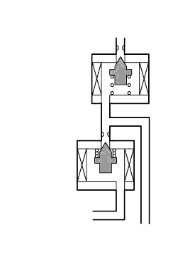
Brake Stroke Simulator Cylinder Assembly
-
The brake stroke simulator cylinder assembly consists of 2 types of coil springs with different spring constants and a stroke simulator cut valve.
-
The brake stroke simulator cylinder assembly provides a pedal stroke in accordance with the driver's pedal effort during braking. Containing 2 types of coil springs with different spring constants, the brake stroke simulator cylinder assembly provides pedal stroke characteristics in 2 stages in relation to the master cylinder pressure.
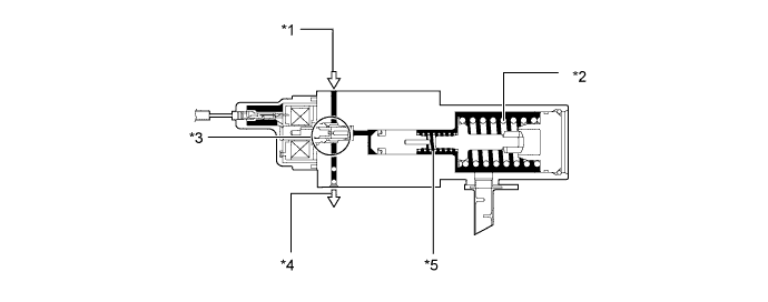
Text in Illustration *1 From Master Cylinder Sub-assembly *2 Coil Spring *3 Stroke Simulator Cut Valve *4 To Wheel Cylinders *5 Coil Spring - -
-
-
Brake Booster Pump Assembly
-
The brake booster pump assembly consists of a pump, accumulator and pump motor.
-
Inside the accumulator, the high-pressurized nitrogen gas is charged and sealed. In addition, metallic bellows-formed tube is used, in order to enhance the gastight performance of the accumulator.
-
A plunger type pump is used. This pump is operated by the rotation of a motor driven cam, to supply high-pressure fluid to the accumulator.
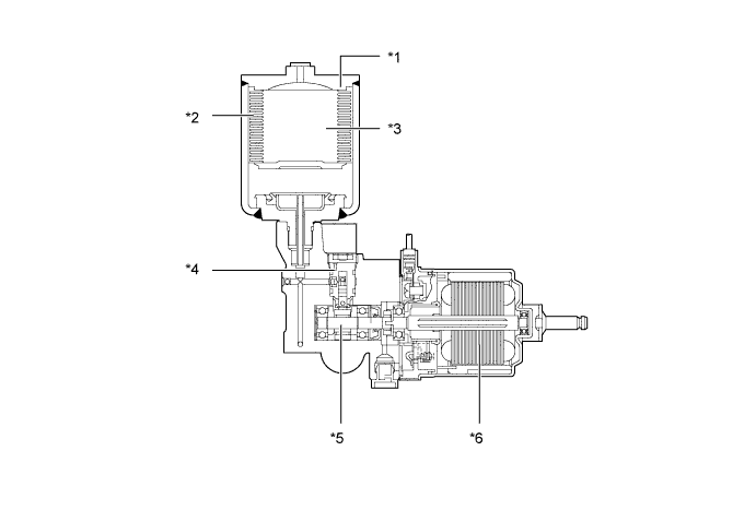
Text in Illustration *1 Accumulator *2 Bellows-formed *3 Nitrogen Gas *4 Pump *5 Cam *6 Pump Motor
-
-
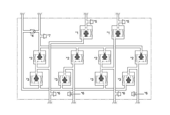
Brake Actuator
-
The 2 master cylinder pressure sensors, 4 wheel cylinder pressure sensors, and an accumulator pressure sensor are installed in the brake actuator.
-
The construction of the brake actuator, and the role of each part, is as follows:
*1 Master Cylinder Cut Solenoid Valve (2-position Type)
-
When the brake pedal is depressed, this valve cuts the hydraulic passage between the master cylinder and its wheel cylinder.
-
When the brake pedal is not depressed or a failure occurs in the hydraulic power source portion, the valves open to maintain the hydraulic passage to the front wheel cylinders and ensure braking.
-
When a failure occurs, a greater effort than normal is required to depress the brake pedal.
*2 Pressure Application Valve (Linear Type) These valves, which are controlled by the skid control ECU, regulate the fluid pressure from the accumulator in order to amplify the fluid pressure to the wheel cylinders. *3 Pressure Reduction Valve (Linear Type) These valves, which are controlled by the skid control ECU, regulate the fluid pressure in order to reduce the fluid pressure to the wheel cylinders. *4 Relief Valve Returns the brake fluid to the reservoir tank to prevent excessive pressure if the pump operates continuously due to a malfunction of the accumulator pressure sensor. *5 Master Cylinder Pressure Sensor The master cylinder pressure sensor converts the fluid pressure generated by the master cylinder into electrical signals and transmits them to the skid control ECU. Accordingly, the skid control ECU determines the braking force required by the driver. *6 Wheel Cylinder Pressure Sensor These sensors detect the fluid pressure that acts on their respective wheel cylinders and transmits the pressure to the skid control ECU to provide feedback. Accordingly, the skid control ECU can monitor the fluid pressure of the wheel cylinders and control the pressure application solenoid valves and the pressure reduction solenoid valves, in order to achieve the optimal wheel cylinder pressures. *7 Accumulator Pressure Sensor The accumulator pressure sensor constantly monitors the brake fluid pressure in the accumulator and transmits a signal to the skid control ECU. Accordingly, the skid control ECU controls the pump motor. -
-
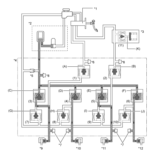
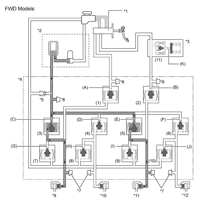
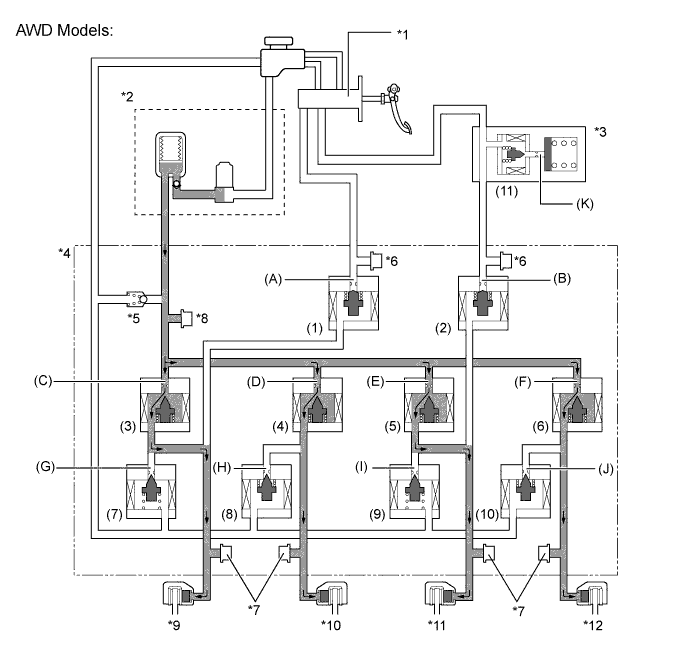
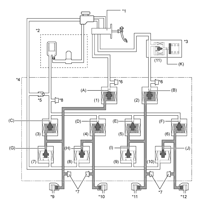
The brake actuator is constructed with the following hydraulic circuit:
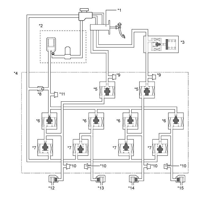
Text in Illustration *1 Master Cylinder Sub-assembly *2
-
Brake Booster Pump Assembly
-
Accumulator
-
Pump
*3 Brake Stroke Simulator Cylinder Assembly *4 Brake Actuator *5 Master Cylinder Cut Solenoid Valve (2-position Type) *6 Pressure Application Valve (Linear Type) *7 Pressure Reduction Valve (Linear Type) *8 Relief Valve *9 Master Cylinder Pressure Sensor *10 Wheel Cylinder Pressure Sensor *11 Accumulator Pressure Sensor *12 Front Brake Caliper (Right Side) *13 Rear Brake Caliper (Left Side) *14 Front Brake Caliper (Left Side) *15 Rear Brake Caliper (Right Side) - - -
-
-
Brake Control Power Supply Assembly
-
The brake control power supply assembly is used as an auxiliary power source, in order to supply power to the brake system in a stable manner.
-
This supply assembly contains 12 capacitor cells, which store an electrical charge provided by the (12 V) vehicle power supply. When the voltage of the (12 V) vehicle power supply drops, the electrical charge stored in the capacitor cells is used as an auxiliary power supply for the brake system.
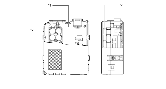
Text in Illustration *1 Control Board *2 Capacitor Cell Tech Tips
Immediately after the power switch is turned OFF, this supply assembly is in the discharging state, and some voltage remains in the capacitors. Therefore, make sure to check for residual voltage and discharge it if necessary, before removing the brake control power supply assembly from the vehicle or opening and inspecting the inside of the brake control power supply assembly case. For details, refer to the Repair Manual.
-
-
-
OPERATION
-
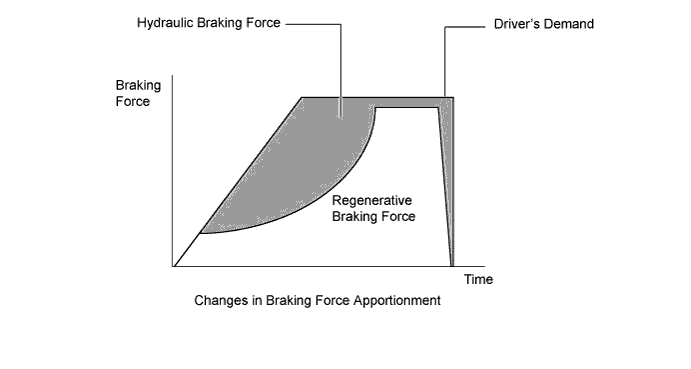
Apportioning of the Brake Force
-
The apportioning of the brake force between hydraulic braking and regenerative braking varies depending on the vehicle speed and length of time the brakes are applied.
-
The apportioning of the brake force between hydraulic braking and regenerative braking is accomplished by controlling the hydraulic brakes so that the total brake force of hydraulic braking and regenerative braking matches the brake force required by the driver.
-
If regenerative braking becomes impossible due to a LEXUS Hybrid Drive malfunction, the brake system performs control so that the entire brake force required by the driver is supplied by the hydraulic brake system.
-
-
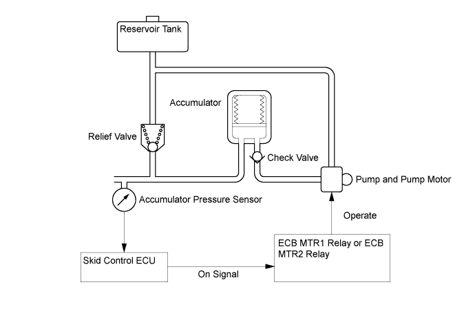
Operation of Brake Booster Pump Assembly
-
The brake fluid that is discharged by the pump passes through the check valve and is stored in the accumulator. The hydraulic pressure that is stored in the accumulator is used for providing the hydraulic pressure that is needed for normal braking and for operating the brake control.
-
The pump motor is activated upon receipt of signals from the skid control ECU to turn on the ECB MTR1 and MTR2 relays.
-
The accumulator pressure sensor constantly monitors the pressure in the accumulator and transmits it to the skid control ECU. If the accumulator pressure drops below the set pressure, the skid control ECU sends an activation signal to the motor relay in order to actuate the pump motor until the pressure in the accumulator reaches the set pressure.
-
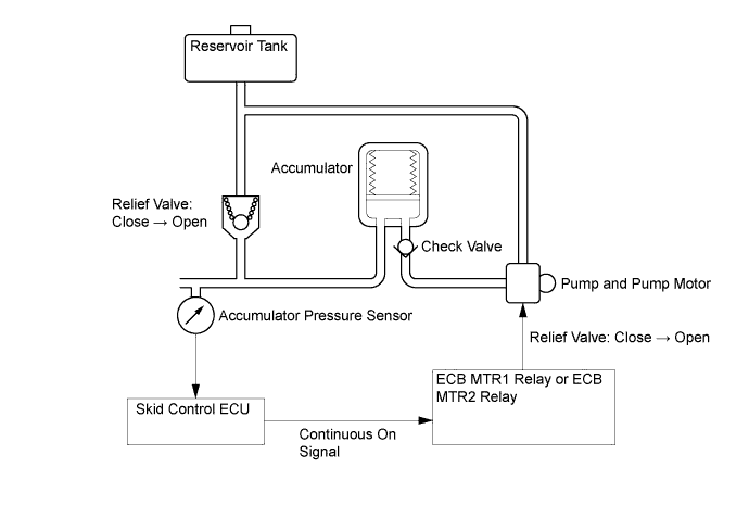
If the pump and the pump motor continue to operate unintendedly, such as due to the failure of the accumulator sensor, a high pressure would be created in the accumulator. At this time, the relief valve will open to return the brake fluid to the reservoir tank, to limit the accumulator pressure.
-
If the accumulator pressure drops abnormally to a level below the pressure set at the ECU, the skid control ECU illuminates the brake warning light (red indicator), the brake warning light (yellow indicator), ABS warning light and slip indicator light. Then, a warning message appears on the multi-information display, and the skid control buzzer assembly sounds to alert the driver of the malfunction.
-
-
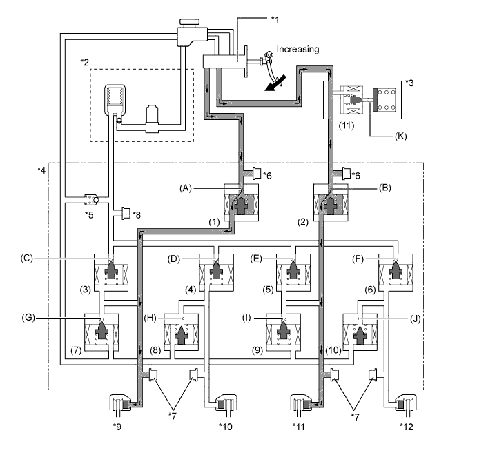
Normal Brake Operation (with Regenerative Braking Cooperative Control)
-
During normal braking, the master cylinder cut solenoid valves are closed and the fluid pressure circuits to the wheel cylinders remain independent. Accordingly, the fluid pressure generated by the master cylinder will not directly cause the wheel cylinders to actuate.
-
The skid control ECU calculates the braking force required by the driver in accordance with the signals received from the master cylinder pressure sensors and the brake pedal stroke sensor.
-
Then, the skid control ECU calculates the ECU request regenerative brake force value out of the required brake force and transmits this calculated value to the power management control ECU. Upon receiving the value, the power management control ECU generates a regenerative brake force.
-
At the same time, the power management control ECU transmits the actual regenerative brake force value (regenerative braking execution value) to the skid control ECU. The skid control ECU controls the solenoid valves in order to cause the hydraulic brake system to generate a brake force which is obtained by subtracting the regenerative braking execution value from the brake force value required by the driver.
-
The skid control ECU calculates the target wheel cylinder pressure (equivalent to the brake force required by the driver) in accordance with the signals received from the master cylinder pressure sensor and the brake pedal stroke sensor.
-
The skid control ECU compares the wheel cylinder pressure sensor signal and the target wheel cylinder pressure. If wheel cylinder pressure is lower than the target, the skid control ECU boosts the pressure using the brake actuator.
-
Accordingly, the fluid pressure in the accumulator is fed into the wheel cylinder. Moreover, this operation is the same when the hydraulic brake force must be increased in order to perform cooperative control in accordance with changes in the regenerative braking force.
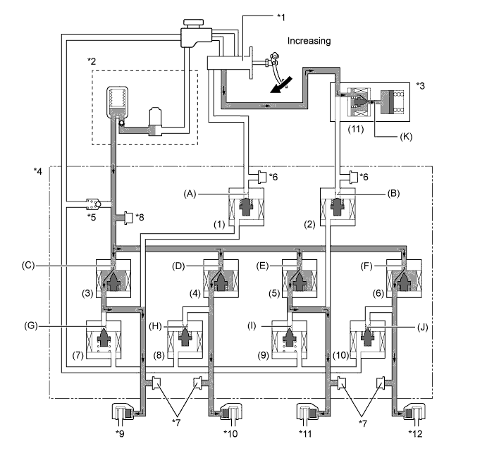
Text in Illustration *1 Master Cylinder Sub-assembly *2
-
Brake Booster Pump Assembly
-
Accumulator
-
Pump
*3 Brake Stroke Simulator Cylinder Assembly *4 Brake Actuator *5 Relief Valve *6 Master Cylinder Pressure Sensor *7 Wheel Cylinder Pressure Sensor *8 Accumulator Pressure Sensor *9 Front Brake Caliper (Right Side) *10 Rear Brake Caliper (Left Side) *11 Front Brake Caliper (Left Side) *12 Rear Brake Caliper (Right Side) -
-
Each valve operates as shown below:
Item Normal Braking Increase Mode (1), (2) Master Cylinder Cut Solenoid Valve ON (Closed) Port: (A), (B) (3), (4), (5), (6) Pressure Application Valve (Linear Type) ON* Port: (C), (D), (E), (F) (7), (9) Pressure Reduction Valve (Linear Type) OFF (Closed) Port: (G), (I) (8), (10) Pressure Reduction Valve (Linear Type) ON (Closed) Port: (H), (J) (11) Stroke Simulator Cut Solenoid Valve ON (Open) Port: (K) *: The solenoid valve constantly regulates the amount of opening of the port in order to control the fluid pressure.
-
The skid control ECU calculates the target wheel cylinder pressure (equivalent to the brake force required by the driver) in accordance with the signals received from the master cylinder pressure sensor and the brake pedal stroke sensor.
-
The skid control ECU compares the wheel cylinder pressure signal with the target wheel cylinder pressure. If they are equal, the skid control ECU controls the brake actuator in the hold state.
-
Accordingly, the wheel cylinder will be held at a constant pressure.
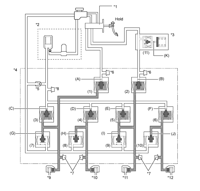
Text in Illustration *1 Master Cylinder Sub-assembly *2
-
Brake Booster Pump Assembly
-
Accumulator
-
Pump
*3 Brake Stroke Simulator Cylinder Assembly *4 Brake Actuator *5 Relief Valve *6 Master Cylinder Pressure Sensor *7 Wheel Cylinder Pressure Sensor *8 Accumulator Pressure Sensor *9 Front Brake Caliper (Right Side) *10 Rear Brake Caliper (Left Side) *11 Front Brake Caliper (Left Side) *12 Rear Brake Caliper (Right Side) -
-
Each valve operates as shown below:
Item Normal Braking Holding Mode (1), (2) Master Cylinder Cut Solenoid Valve ON (Closed) Port: (A), (B) (3), (4), (5), (6) Pressure Application Valve (Linear Type) OFF (Closed) Port: (C), (D), (E), (F) (7), (9) Pressure Reduction Valve (Linear Type) OFF (Closed) Port: (G), (I) (8), (10) Pressure Reduction Valve (Linear Type) ON (Closed) Port: (H), (J) (11) Stroke Simulator Cut Solenoid Valve ON (Open) Port: (K) -
The skid control ECU calculates the target wheel cylinder pressure (equivalent to the brake force required by the driver) in accordance with the signals received from the master cylinder pressure sensor and the brake pedal stroke sensor.
-
The skid control ECU compares the wheel cylinder pressure signal with the target wheel cylinder pressure. If wheel cylinder pressure is higher than the target, the skid control ECU reduces the pressure using the brake actuator.
-
Accordingly, the pressure in the wheel cylinder decreases.
-
Moreover, this operation is the same when the hydraulic brake force must be decreased in order to perform cooperative control in accordance with changes in the regenerative braking force.
Text in Illustration *1 Master Cylinder Sub-assembly *2
-
Brake Booster Pump Assembly
-
Accumulator
-
Pump
*3 Brake Stroke Simulator Cylinder Assembly *4 Brake Actuator *5 Relief Valve *6 Master Cylinder Pressure Sensor *7 Wheel Cylinder Pressure Sensor *8 Accumulator Pressure Sensor *9 Front Brake Caliper (Right Side) *10 Rear Brake Caliper (Left Side) *11 Front Brake Caliper (Left Side) *12 Rear Brake Caliper (Right Side) -
-
Each valve operates as shown below:
Item Normal Braking Reduction Mode (1), (2) Master Cylinder Cut Solenoid Valve ON (Closed) Port: (A), (B) (3), (4), (5), (6) Pressure Application Valve (Linear Type) OFF (Closed) Port: (C), (D), (E), (F) (7), (9) Pressure Reduction Valve (Linear Type) ON* Port: (G), (I) (8), (10) Pressure Reduction Valve (Linear Type) ON* Port: (H), (J) (11) Stroke Simulator Cut Solenoid Valve ON (Open) Port: (K) *: The solenoid valve constantly regulates the amount of opening of the port in order to control the fluid pressure.
-
-
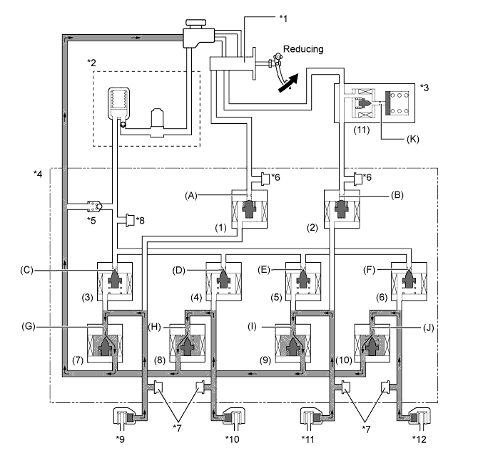
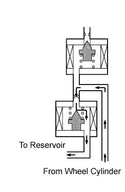
Electronically Controlled Brake System Stops or During Power Supply Malfunction
-
If the electronically controlled brake system stops or no accumulator pressure is supplied due to some malfunction, the skid control ECU operates the fail safe function.
-
This function opens the master cylinder solenoid valve in the brake actuator, in order to secure a fluid passage between the master cylinder and the wheel cylinder. Thus, the brakes can be applied by operating only the front wheel cylinders using the fluid pressure generated by the master cylinder.
-
At this time, port (K) of the stroke simulator cut solenoid valve closes in order to prevent the fluid pressure generated by the master cylinder from being negatively affected by the operation of the stroke simulator.
-
In addition, to inform the driver, the skid control ECU sends a warning signal to the combination meter assembly, in addition to sounding the skid control buzzer assembly.
Text in Illustration *1 Master Cylinder Sub-assembly *2
-
Brake Booster Pump Assembly
-
Accumulator
-
Pump
*3 Brake Stroke Simulator Cylinder Assembly *4 Brake Actuator *5 Relief Valve *6 Master Cylinder Pressure Sensor *7 Wheel Cylinder Pressure Sensor *8 Accumulator Pressure Sensor *9 Front Brake Caliper (Right Side) *10 Rear Brake Caliper (Left Side) *11 Front Brake Caliper (Left Side) *12 Rear Brake Caliper (Right Side) -
-
Each valve operates as shown below:
Item Fail-safe Mode (1), (2) Master Cylinder Cut Solenoid Valve OFF (Open) Port: (A), (B) (3), (4), (5), (6) Pressure Application Valve (Linear Type) OFF (Closed) Port: (C), (D), (E), (F) (7), (9) Pressure Reduction Valve (Linear Type) OFF (Closed) Port: (G), (I) (8), (10) Pressure Reduction Valve (Linear Type) OFF (Open) Port: (H), (J) (11) Stroke Simulator Cut Solenoid Valve OFF (Closed) Port: (K)
-
-
ABS with EBD Operation
-
Based on the signals received from the 4 speed sensors, the skid control ECU calculates each wheel speed and deceleration, and checks for wheel slippage. According to wheel slippage, the skid control ECU controls each pressure application valve and pressure reduction valve in order to adjust the fluid pressure of the each wheel cylinder in the following 3 modes: pressure reduction, pressure holding, pressure increase modes.
Not Activated Normal Braking - - Activated Increase Mode Holding Mode Reduction Mode Hydraulic Circuit 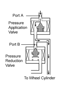
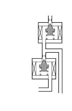
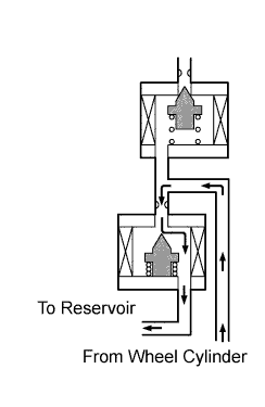
Front Pressure Application Valve (Port A) ON* OFF (Closed) OFF (Closed) Pressure Reduction Valve (Port B) OFF (Closed) OFF (Closed) ON* Hydraulic Circuit 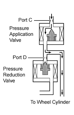
Rear Pressure Application Valve (Port C) ON* OFF (Closed) OFF (Closed) Pressure Reduction Valve (Port D) ON (Closed) ON (Closed) ON* Wheel Cylinder Pressure Increase Hold Reduction *: The solenoid valve constantly regulates the amount of opening of the port in order to control the fluid pressure.
-
-
Brake Assist Operation
-
In the event of emergency braking, the skid control ECU detects the driver's intention based on the speed of the pressure increase in the master cylinder determined by the pressure sensor signals. If the ECU judges the need for the additional brake assist, additional fluid pressure is generated by the pump in the actuator and directed to the wheel cylinders.
Text in Illustration *1 Master Cylinder Sub-assembly *2
-
Brake Booster Pump Assembly
-
Accumulator
-
Pump
*3 Brake Stroke Simulator Cylinder Assembly *4 Brake Actuator *5 Relief Valve *6 Master Cylinder Pressure Sensor *7 Wheel Cylinder Pressure Sensor *8 Accumulator Pressure Sensor *9 Front Brake Caliper (Right Side) *10 Rear Brake Caliper (Left Side) *11 Front Brake Caliper (Left Side) *12 Rear Brake Caliper (Right Side) -
-
Each valve operates as shown below:
Item Normal Braking Increase Mode Brake Assist Activated (1), (2) Master Cylinder Cut Solenoid Valve ON (Closed) ON (Closed)) Port: (A), (B) (3), (4), (5), (6) Pressure Application Valve (Linear Type) ON* ON* Port: (C), (D), (E), (F) (7), (9) Pressure Reduction Valve (Linear Type) OFF (Closed) OFF (Closed) Port: (G), (I) (8), (10) Pressure Reduction Valve (Linear Type) ON (Closed) ON (Closed) Port: (H), (J) (11) Stroke Simulator Cut Solenoid Valve ON (Open) ON (Open) Port: (K) *: The solenoid valve constantly regulates the amount of opening of the port in order to control the fluid pressure.
-
-
TRC Operation
-
The fluid pressure generated by the pump is regulated by the pressure application solenoid valve and pressure reduction solenoid valve to the required pressure. Thus, the wheel cylinders of the drive wheels are controlled in the following 3 modes: pressure reduction, pressure holding, and pressure increase modes, to restrain the slippage of the drive wheels.
-
The pressure application valve and the pressure reduction valve are turned on/off according to the ABS operation pattern.
-
The diagram shows the hydraulic circuit in the pressure increase mode when the TRC function is activated.
Text in Illustration *1 Master Cylinder Sub-assembly *2
-
Brake Booster Pump Assembly
-
Accumulator
-
Pump
*3 Brake Stroke Simulator Cylinder Assembly *4 Brake Actuator *5 Relief Valve *6 Master Cylinder Pressure Sensor *7 Wheel Cylinder Pressure Sensor *8 Accumulator Pressure Sensor *9 Front Brake Caliper (Right Side) *10 Rear Brake Caliper (Left Side) *11 Front Brake Caliper (Left Side) *12 Rear Brake Caliper (Right Side) -
-
Each valve operates as shown below:
Item TRC not Activated TRC Activated Increase Mode Holding Mode Reduction Mode (1), (2) Master Cylinder Cut Solenoid Valve ON (Closed) ON (Closed) ON (Closed) ON (Closed) Port: (A), (B) Front Brake (3), (5) Pressure Application Valve (Linear Type) OFF (Closed) ON* OFF (Closed) OFF (Closed) Port: (C), (E) (7), (9) Pressure Reduction Valve (Linear Type) OFF (Closed) OFF (Closed) OFF (Closed) ON* Port: (G), (I) Wheel Cylinder Pressure - Increase Hold Reduce Rear Brake (4), (6) Pressure Application Valve (Linear Type) OFF (Closed) OFF (Closed) OFF (Closed) OFF (Closed) Port: (D), (F) (8), (10) Pressure Reduction Valve (Linear Type) OFF (Open) ON (Closed) ON (Closed) ON* Port: (H), (J) Wheel Cylinder Pressure - - - - (11) Stroke Simulator Cut Solenoid Valve ON (Open) ON (Open) ON (Open) ON (Open) Port: (K) *: The solenoid valve constantly regulates the amount of opening of the port in order to control the fluid pressure.
Text in Illustration *1 Master Cylinder Sub-assembly *2
-
Brake Booster Pump Assembly
-
Accumulator
-
Pump
*3 Brake Stroke Simulator Cylinder Assembly *4 Brake Actuator *5 Relief Valve *6 Master Cylinder Pressure Sensor *7 Wheel Cylinder Pressure Sensor *8 Accumulator Pressure Sensor *9 Front Brake Caliper (Right Side) *10 Rear Brake Caliper (Left Side) *11 Front Brake Caliper (Left Side) *12 Rear Brake Caliper (Right Side) -
-
Each valve operates as shown below:
Item TRC not Activated TRC Activated Increase Mode Holding Mode Reduction Mode (1), (2) Master Cylinder Cut Solenoid Valve ON (Closed) ON (Closed) ON (Closed) ON (Closed) Port: (A), (B) Front Brake (3), (5) Pressure Application Valve (Linear Type) OFF (Closed) ON* OFF (Closed) OFF (Closed) Port: (C), (E) (7), (9) Pressure Reduction Valve (Linear Type) OFF (Closed) OFF (Closed) OFF (Closed) ON* Port: (G), (I) Wheel Cylinder Pressure - Increase Hold Reduce Rear Brake (4), (6) Pressure Application Valve (Linear Type) OFF (Closed) ON* OFF (Closed) OFF (Closed) Port: (D), (F) (8), (10) Pressure Reduction Valve (Linear Type) OFF (Open) ON (Closed) ON (Closed) ON* Port: (H), (J) Wheel Cylinder Pressure - Increase Hold Reduce (11) Stroke Simulator Cut Solenoid Valve ON (Open) ON (Open) ON (Open) ON (Open) Port: (K) *: The solenoid valve constantly regulates the amount of opening of the port in order to control the fluid pressure.
-
-
VSC Operation
-
The VSC function controls the solenoid valves in order to send the fluid pressure stored in the accumulator to the brake wheel cylinders at the respective wheels, through routes that are different from those used during normal braking. Thus, the function operates in the following 3 modes: pressure reduction, pressure holding, and pressure increase. As a result, the tendency of the front wheels or the rear wheels to skid is restrained.
-
In the front wheel skid tendency, this management function applies the brake to the both front wheels and rear wheel of the inner side of the turn. Also, depending on whether the brake is on or off and the condition of the vehicle, there are circumstances in which the brake might not be applied to the wheels even if those wheels are targeted for braking. The diagram below shows the hydraulic circuit in the pressure increase mode, as it restrains the front wheel skid condition while the vehicle makes a right turn.
-
The pressure application valve and the pressure reduction valve are turned on/off according to the ABS operation pattern.
Text in Illustration *1 Master Cylinder Sub-assembly *2
-
Brake Booster Pump Assembly
-
Accumulator
-
Pump
*3 Brake Stroke Simulator Cylinder Assembly *4 Brake Actuator *5 Relief Valve *6 Master Cylinder Pressure Sensor *7 Wheel Cylinder Pressure Sensor *8 Accumulator Pressure Sensor *9 Front Brake Caliper (Right Side) *10 Rear Brake Caliper (Left Side) *11 Front Brake Caliper (Left Side) *12 Rear Brake Caliper (Right Side) -
-
Each valve operates as shown below:
Item VSC not Activated VSC Activated Increase Mode Holding Mode Reduction Mode (1), (2) Master Cylinder Cut Solenoid Valve ON (Closed) ON (Closed) ON (Closed) ON (Closed) Port: (A), (B) Front Brake (3) Pressure Application Valve (Linear Type) OFF (Closed) ON* OFF (Closed) OFF (Closed) Port: (C) (5) Pressure Application Valve (Linear Type) OFF (Closed) ON* OFF (Closed) OFF (Closed) Port: (E) (7) Pressure Reduction Valve (Linear Type) OFF (Closed) OFF (Closed) OFF (Closed) ON* Port: (G) (9) Pressure Reduction Valve (Linear Type) OFF (Closed) OFF (Closed) OFF (Closed) ON* Port: (I) Wheel Cylinder Pressure Right - Increase Hold Reduce Left Rear Brake (4) Pressure Application Valve (Linear Type) OFF (Closed) OFF (Closed) OFF (Closed) OFF (Closed) Port: (D) (6) Pressure Application Valve (Linear Type) OFF (Closed) ON* OFF (Closed) OFF (Closed) Port: (F) (8) Pressure Reduction Valve (Linear Type) OFF (Open) OFF (Open) OFF (Open) ON* Port: (H) (10) Pressure Reduction Valve (Linear Type) OFF (Open) ON (Closed) ON (Closed) ON* Port: (J) Wheel Cylinder Pressure Right - Increase Hold Reduce Left - - - (11) Stroke Simulator Cut Solenoid Valve ON (Open) ON (Open) ON (Open) ON (Open) Port: (K) *: The solenoid valve constantly regulates the amount of opening of the port in order to control the fluid pressure.
-
In rear wheel skid tendency, this management function applies the brake to the front and rear wheel of the outer circle of the turn. In some cases, the skid control ECU applies the brake to the rear wheels, as necessary. As an example, the diagram below shows the hydraulic circuit in the pressure increase mode, as it restrains the rear wheel skid condition while the vehicle makes a right turn.
-
As in front wheel skid restraint control, the pressure application valve and the pressure reduction valve are turned ON/OFF according to the ABS operating pattern.
Text in Illustration *1 Master Cylinder Sub-assembly *2
-
Brake Booster Pump Assembly
-
Accumulator
-
Pump
*3 Brake Stroke Simulator Cylinder Assembly *4 Brake Actuator *5 Relief Valve *6 Master Cylinder Pressure Sensor *7 Wheel Cylinder Pressure Sensor *8 Accumulator Pressure Sensor *9 Front Brake Caliper (Right Side) *10 Rear Brake Caliper (Left Side) *11 Front Brake Caliper (Left Side) *12 Rear Brake Caliper (Right Side) -
-
Each valve operates as shown below:
Item VSC not Activated VSC Activated Increase Mode Holding Mode Reduction Mode (1), (2) Master Cylinder Cut Solenoid Valve ON (Closed) ON (Closed) ON (Closed) ON (Closed) Port: (A), (B) Front Brake (3) Pressure Application Valve (Linear Type) OFF (Closed) OFF (Closed) OFF (Closed) OFF (Closed) Port: (C) (5) Pressure Application Valve (Linear Type) OFF (Closed) ON*1 OFF (Closed) OFF (Closed) Port: (E) (7) Pressure Reduction Valve (Linear Type) OFF (Closed) OFF (Closed) OFF (Closed) OFF (Closed) Port: (G) (9) Pressure Reduction Valve (Linear Type) OFF (Closed) OFF (Closed) OFF (Closed) ON*1 Port: (I) Wheel Cylinder Pressure Right - - - - Left - Increase Hold Reduce Rear Brake (4) Pressure Application Valve (Linear Type) OFF (Closed) ON*1 OFF (Closed) OFF (Closed) Port: (D) (6) Pressure Application Valve (Linear Type) OFF (Closed) OFF (Closed)/ON*1, 2 OFF (Closed) OFF (Closed) Port: (F) (8) Pressure Reduction Valve (Linear Type) OFF (Open) ON (Closed) ON (Closed) ON*1 Port: (H) (10) Pressure Reduction Valve (Linear Type) OFF (Open) OFF (Open) OFF (Open)/ON (Closed)*2 OFF (Open)/ON*1, 2 Port: (J) Wheel Cylinder Pressure Right - - - - Left - Increase Hold Reduce (11) Stroke Simulator Cut Solenoid Valve ON (Open) ON (Open) ON (Open) ON (Open) Port: (K) *1: The solenoid valve constantly regulates the amount of opening of the port in order to control the fluid pressure.
*2: In some cases, the skid control ECU applies the brakes of the rear wheels, as necessary.
-
-
Hill-start Assist Control Operation
-
Hill-start Assist Control helps maintain 4-wheel hydraulic pressure by operating the pressure application valve and pressure reduction valve from when the driver releases the brake pedal until depressing the accelerator pedal.
-
Based on the information provided by various sensors, switches, and the power management control ECU, the skid control ECU detects if Hill-start Assist Control can operate.
-
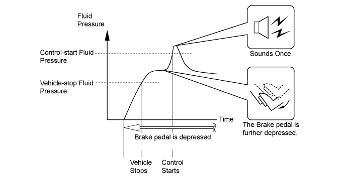
When Hill-start Assist Control operation starts, the skid control buzzer assembly will sound once. During Hill-start Assist Control operation, the slip indicator light blinks and the stop lights are illuminated.
-
The skid control ECU starts the Hill-start Assist Control operation when the operating conditions below are met and the driver further depresses the brake pedal, causing the fluid pressure to exceed the control-start fluid pressure.
Hill-start Assist Control Operating Conditions
-
Shift lever is in R, N, D or S (in a position other than P).
-
The accelerator pedal is not depressed.
-
The vehicle is at a standstill.
-
The parking brake is not applied.
-
-
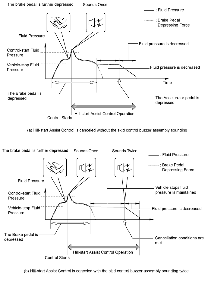
If any one of the below conditions is met during Hill-start Assist Control operation, Hill-start Assist Control will be cancelled causing the slip indicator light to turn off. There are conditions which may result in control being cancelled. In these cases, the skid control buzzer assembly will be sounded to inform the driver.
Skid Control Buzzer Assembly Cancellation Condition (a) Does Not Sound The driver depresses the accelerator pedal. (b) Sounds Twice
-
The driver moves the shift lever to the P position.
-
The driver depresses the parking brake pedal.
-
The driver depresses the brake pedal.
-
The driver releases the brake pedal for several seconds.
-
The driver keeps the brake pedal depressed continually for 3 minutes.
Text in Illustration *1 Master Cylinder Sub-assembly *2
-
Brake Booster Pump Assembly
-
Accumulator
-
Pump
*3 Brake Stroke Simulator Cylinder Assembly *4 Brake Actuator *5 Relief Valve *6 Master Cylinder Pressure Sensor *7 Wheel Cylinder Pressure Sensor *8 Accumulator Pressure Sensor *9 Front Brake Caliper (Right Side) *10 Rear Brake Caliper (Left Side) *11 Front Brake Caliper (Left Side) *12 Rear Brake Caliper (Right Side) -
-
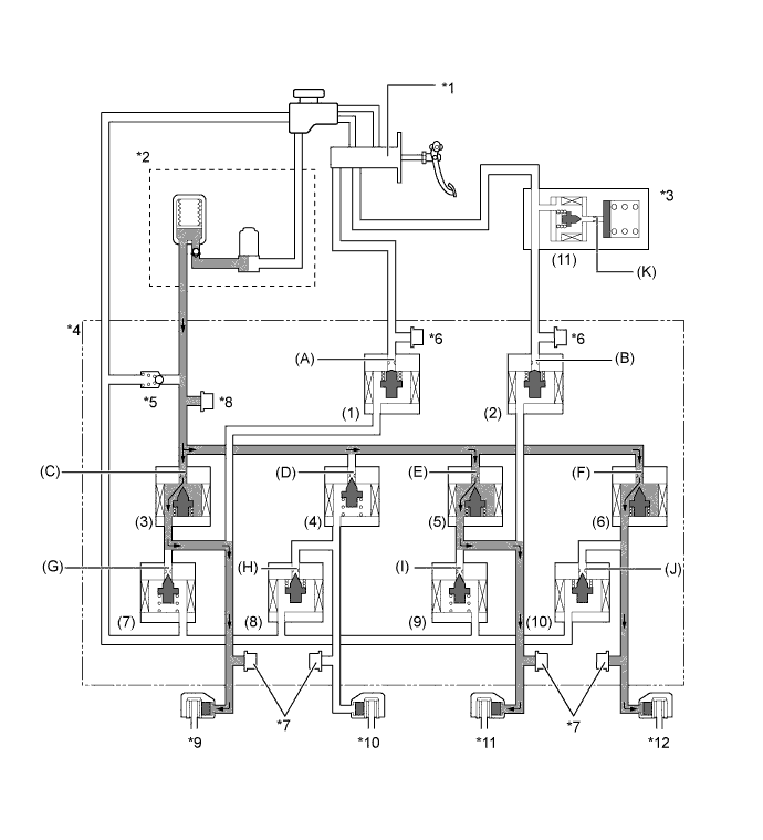
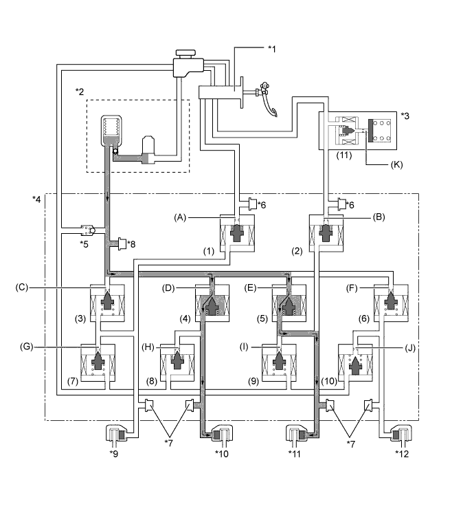
Each valve operates as shown below:
Item Hill-start Assist Control not Activated Hill-start Assist Control Activated Holding Mode Reduction Mode (1), (2) Master Cylinder Cut Solenoid Valve ON (Closed) ON (Closed) ON (Closed) Port: (A), (B) Front Brake (3) Pressure Application Valve (Linear Type) OFF (Closed) OFF (Closed) OFF (Closed) Port: (C) (5) Pressure Application Valve (Linear Type) OFF (Closed) OFF (Closed) OFF (Closed) Port: (E) (7) Pressure Reduction Valve (Linear Type) OFF (Closed) OFF (Closed) ON (Open) Port: (G) (9) Pressure Reduction Valve (Linear Type) OFF (Closed) OFF (Closed) ON (Open) Port: (I) Rear Brake (4) Pressure Application Valve (Linear Type) OFF (Closed) OFF (Closed) OFF (Closed) Port: (D) (6) Pressure Application Valve (Linear Type) OFF (Closed) OFF (Closed) OFF (Closed) Port: (F) (8) Pressure Reduction Valve (Linear Type) OFF (Open) ON (Closed) OFF (Open) Port: (H) (10) Pressure Reduction Valve (Linear Type) OFF (Open) ON (Closed) OFF (Open) Port: (J) (11) Stroke Simulator Cut Solenoid Valve ON (Open) ON (Open) ON (Open) Port: (K)
-
-
Fail-safe
-
If a failure occurs in the skid control ECU, sensors, or brake actuator, the system continues performing brake control by excluding the failed area and using only the areas that are operating normally.
-
If the regenerative brake becomes unusable due to a failure in communication with the power management control ECU, the skid control ECU uses the hydraulic brake force to control the entire braking force.
-
-
Diagnosis
-
If the skid control ECU detects a malfunction in the brake control system, the warning lights in the combination meter assembly light up and warning message on the multi-information display displays to alert the driver of the malfunction. At the same time, the skid control ECU stores Diagnostic Trouble Codes (DTCs) in memory.
-
If the skid control ECU detects a malfunction during a sensor signal check (test mode), it stores the DTCs in its memory.
-
For details, refer to the Repair Manual.
-
-