TIRE PRESSURE WARNING SYSTEM DETAILS
-
FUNCTION OF MAIN COMPONENTS
Component Function Tire Pressure Monitor Valve Sub-assembly Detects the tire pressure, internal temperature and rotational acceleration of the tire, and transmits the measured values and the ID code to the tire pressure monitor receiver assembly. Tire Pressure Monitor Receiver Assembly Receives the data from the tire pressure monitor valve sub-assembly and monitors the tire inflation pressure. Tire Pressure Monitor ECU
-
Receives the data from the tire pressure monitor receiver assembly the tire inflation pressure.
-
Outputs the respective signal to the combination meter assembly when a drop in the tire inflation pressure, a system malfunction or the beginning of initialization is detected.
-
When the tire pressure monitor receiver assembly detects a problem with the vehicle speed signal, it uses the engine speed as backup information. If the engine speed is higher than a specified value, the tire pressure monitor receiver assembly determines that the vehicle is being driven.
Combination Meter Assembly Transmits the vehicle speed signal to the tire pressure monitor receiver assembly. Tire Pressure Warning Light Illuminates or stays on after blinking for 1 minute to warn the driver in accordance with the signal from the tire pressure monitor receiver assembly. Multi-information Display Displays the identified tire pressure to inform or warn the driver. Tire Pressure Warning Reset Switch The appropriate pressures of the tires currently mounted on the vehicle are stored in the tire pressure monitor receiver assembly by operating the tire pressure warning reset switch. -
-
FUNCTION
-
Tire Inflation Pressure Display Function
-
The multi-information display shows the following to inform or warn the driver of the tire pressure:
Condition Multi-information Display Tire pressure is normal 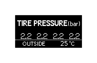
Models with Temporary Spare Tire
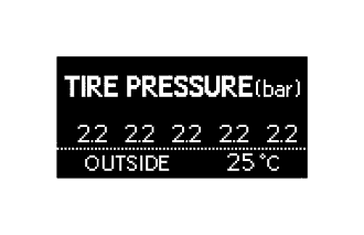
Models with Full Size Spare Tire
Tire pressure is below the warning threshold 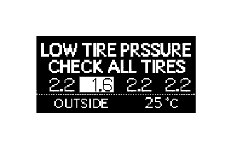
Models with Temporary Spare Tire
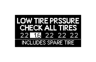
Models with Full Size Spare Tire
There is a system malfunction 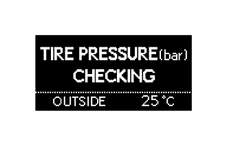
Models compliant with ECE-R64 legal regulations
-
-
Warning Function
-
The tire pressure monitor receiver assembly has 2 warning methods that are used, depending on the condition detected.
Tire Pressure Warning Light Detection Condition Illuminates*1 The tire pressure monitor receiver assembly has detected that a tire pressure becomes lower than the threshold. The threshold varies according to the initialization value. Stays on after blinking for 1 minute*2 The tire pressure monitor receiver assembly has detected a malfunction in the system.
-
*1: If the tire pressure warning light illuminates, adjust the tire inflation pressure.
-
*2: If the tire pressure warning light stays on after blinking for 1 minute, the system is malfunctioning and must be repaired to turn off the light.
-
-
-
Initial Check Function
-
After the power switch is turned on (IG), the tire pressure monitor receiver assembly illuminates the tire pressure warning light for 3 seconds to check the warning light circuit.
-
-
Initialization Function
-
The warning threshold is calculated from the tire pressure and memorized in the tire pressure monitor receiver assembly. Therefore, the tire pressure monitor receiver assembly should be initialized after:
-
The recommended tire inflation pressure changes due to changes in vehicle weight, speed conditions or tire size.
-
The Tire pressure monitor receiver assembly or the tire pressure monitor valve sub-assembly are replaced.
-
The tires are rotated on a vehicle with different recommended tire inflation pressures for the front and rear tires.
-
The tire pressure is adjusted.*
*: Models compliant with ECE-R64 legal regulations
-
-
Initialization starts after the tire pressure warning reset switch is pressed and held (with the power switch on (IG) and with the vehicle stopped) and the tire pressure warning light blinks slowly 3 times.
-
Before performing initialization, adjust the tire inflation pressure to the recommended pressure when the tires are cold. For details, refer to the Repair Manual.
-
The tire pressure warning reset switch is not used to cancel the warning. Do not press the tire pressure warning reset switch to turn off the tire pressure warning light.*
*: Models compliant with FMVSS138 legal regulations
-
-
-
CONSTRUCTION
-
Tire Pressure Monitor Valve Sub-assembly
-
The tire pressure monitor valve sub-assemblies are integrated in the tire valves. Each tire pressure monitor valve sub-assembly consists of a lithium battery, sensor and transmitter.
-
Make sure not to damage the urethane covered backside of the transmitter (the surface opposite to the side with the ID code) with anything sharp.
-
The transmitter directly measures tire inflation pressure and temperature to see if the vehicle can continue to run.
-
The transmitter transmits the measured tire inflation pressure and temperature values to the tire pressure monitor receiver assembly on a frequency of 315 MHz*1 or 433 MHz*2.
*1: Models compliant with FMVSS138 legal regulations
*2: Models compliant with ECE-R64 legal regulations
-
The ID code is written on the tire pressure monitor valve sub-assembly.
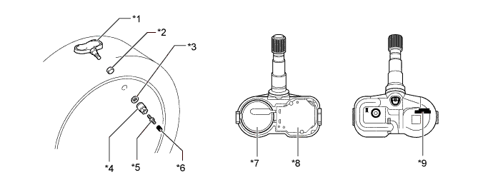
Text in Illustration *1 Tire Pressure Monitor Valve Sub-assembly *2 Grommet *3 Washer *4 Nut *5 Tire Valve Core *6 Cap *7 Sensor and Transmitter *8 Lithium Battery *9 ID Code (Hexadecimal 7 Digits) - - Tech Tips
-
The lithium batteries of the tire pressure monitor valve sub-assembly are a non-replaceable type. If the lithium battery is depleted, the tire pressure monitor valve sub-assembly must be replaced.
-
A new tire pressure monitor valve sub-assembly is shipped in sleep mode to prevent the battery from depleting in storage. When the pressure in the detection portion of the tire pressure monitor valve sub-assembly increases or decreases by 40 kPa (0.4 kgf/cm2, 5.8 psi) within 30 seconds, the tire pressure monitor valve sub-assembly automatically cancels sleep mode. Once sleep mode is canceled, the tire pressure monitor valve sub-assembly cannot return to sleep mode.
-
After a tire pressure monitor valve sub-assembly is replaced, the ID of the tire pressure monitor valve sub-assembly must be registered in the tire pressure monitor receiver assembly. To register an ID, use the Global TechStream (GTS) to enter the ID code that is indicated on the tire pressure monitor valve sub-assembly.
-
When replacing a tire pressure monitor valve sub-assembly, each ID codes of tire pressure monitor valve sub-assembly must be registered. Even if only 1 tire pressure monitor valve sub-assembly is replaced, the ID codes of all the tire pressure monitor valve sub-assembly must be registered again. Record all existing ID codes before beginning the process to enter new ID codes.
-
For details, refer to the Repair Manual.
-
-
-
-
DIAGNOSIS
-
To inform the driver when the tire pressure monitor receiver assembly detects a malfunction in the system, the tire pressure monitor receiver assembly will blink the tire pressure warning light for 1 minute, after which the light will stay on. It will also store Diagnostic Trouble Codes (DTCs) in memory.
-
5-digit DTCs can be read by connecting the Global TechStream (GTS) to the DLC3. For details, refer to the Repair Manual.
-