HYBRID CONTROL SYSTEM DETAILS
-
FUNCTION OF MAIN COMPONENTS
-
The main components in the hybrid control system have the following functions:
Component Function P313 Hybrid Transaxle (Hybrid Vehicle Transaxle Assembly) Motor Generator 1 (MG1)
-
MG1, which is driven by the engine, generates high-voltage electricity in order to operate MG2 and MGR and/or charge the HV battery. Also, it functions as a starter to start the engine.
-
MG1 is operated so that the gear ratio of the power split planetary gear unit will optimally suit the driving conditions of the vehicle.
Motor Generator 2 (MG2)
-
Driven by electrical power from MG1 and/or the HV battery, it generates motive force for the front wheels.
-
During braking, or when the accelerator pedal is not depressed, it generates electricity to recharge the HV battery (regenerative braking).
Compound Gear Unit Power Split Planetary Gear Unit:
-
Distributes the engine drive force as appropriate to directly drive the vehicle as well as MG1.
Motor Speed Reduction Planetary Gear Unit:
-
Located between MG2 and the power split planetary gear, the motor speed reduction planetary gear reduces the rotational speed of MG2 in order to increase torque.
Resolver
-
MG1 and MG2 are each equipped with a resolver.
-
Sends the rotational speed and direction of the motor to the Motor Generator ECU (MG ECU).
Temperature Sensor
-
MG1 and MG2 are each equipped with a temperature sensor.
-
Measures the temperature of MG1 and MG2.
Q211 Rear Drive Unit (Rear Traction Motor with Transaxle Assembly) Motor Generator Rear (MGR)
-
Driven by electrical power from MG1 and/or the HV battery, it generates motive force for the rear wheels.
-
During braking, or when the accelerator pedal is not depressed, it generates electricity to recharge the HV battery (Regenerative braking).
Resolver
-
MGR is each equipped with a resolver.
-
Sends the rotational speed and direction of the motor to the Motor Generator ECU (MG ECU).
Temperature Sensor
-
MGR is each equipped with a temperature sensor.
-
Measures the temperature of MGR.
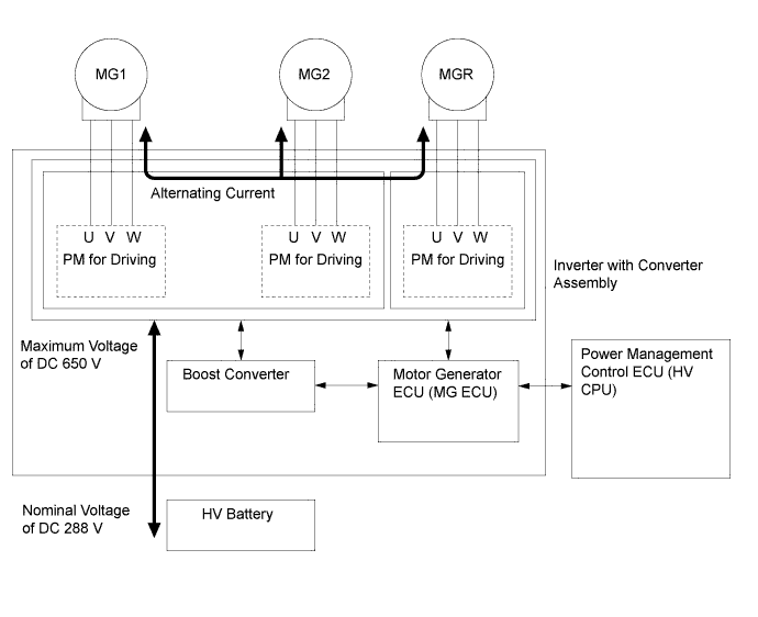
Inverter with Converter Assembly Inverter A device that converts high-voltage DC (HV battery) into AC (MG1, MG2 and MGR) and vice versa (converts AC into DC). Boost Converter Boosts the voltage of the HV battery from DC 288V to a maximum of DC 650 V and vice versa (drops DC 650 V to DC 288 V). DC-DC Converter Drops the HV battery voltage of DC 288 V into approximately DC 14 V in order to supply electricity to body electrical components, as well as to recharge the auxiliary battery. Motor Generator ECU (MG ECU) Controls the inverter and boost converter in accordance with signals received from the power management control ECU (HV CPU), thus operating MG1, MG2, or MGR as either a generator or motor. Temperature Sensors (6)
-
Inverter temperature sensors are provided for the boost converter (2), power module for MG1, MG2 and MGR and coolant.
-
Measures the temperature of boost converter, power module for MG1, MG2 and MGR and coolant.
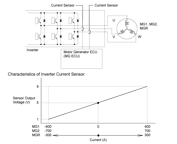
Current Sensors (6)
-
MG1, MG2 and MGR are each provided with 2 current sensors.
-
Measures the current of the MG1, MG2 and MGR
Power Management Control ECU (HV CPU)
-
Performs comprehensive control of the LEXUS Hybrid Drive. This includes the electric continuously variable transmission and HV battery.
-
Information from various sensors as well as from ECUs (battery voltage sensor, Motor Generator ECU (MG ECU), skid control ECU, and power steering ECU) is received, and based on this the required torque and output power is calculated. The power management control ECU (HV CPU) sends the calculated result to the Motor Generator ECU (MG ECU) and skid control ECU.
-
Monitors the State Of Charge (SOC) of the HV battery.
-
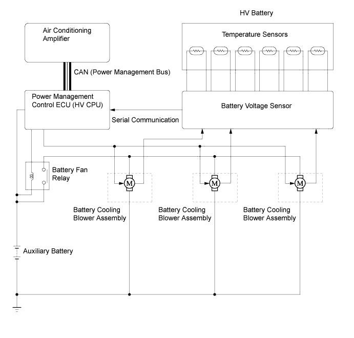
Controls the battery cooling blower assemblies.
-
Controls the DC-DC converter.
ECM The ECM transmits the operating condition of the engine to the power management control ECU (HV CPU). HV Battery Assembly
-
Supplies electrical power to MG1, MG2, and MGR in accordance with the driving conditions of the vehicle.
-
Is charged by MG1, MG2, and MGR in accordance with the SOC and the driving conditions of the vehicle.
-
Has a nominal (approximate) voltage of DC 288 V (actual voltage will vary depending on various conditions such as temperature, charge or discharge).
Hybrid Junction Block Assembly System Main Relays (SMRs) Connect and disconnect the high-voltage power circuit between battery and inverter with converter assembly. The power management control ECU (HV CPU) controls the SMRs by turning them on or off as appropriate HV Battery Current Sensor Measures the current of the HV battery. Battery Voltage Sensor
-
Monitors HV battery conditions such as voltage, temperature and current, and transmits this information to the power management control ECU (HV CPU).
-
Monitors the HV system for breakdown of the electrical insulation.
Skid Control ECU
-
During braking, it calculates the regenerative braking force that is required and transmits it to the power management control ECU (HV CPU).
-
Calculates the motive force that is required during the operation of TRC or VSC and transmits it to the power management control ECU (HV CPU).
-
Transmits a front and rear wheel torque distribution request to the power management control ECU (HV CPU) for the purpose of E-Four system control.
Accelerator Pedal Position Sensor Converts the accelerator pedal position into an electrical signal and outputs it to the power management control ECU (HV CPU). Shift Lever Position Sensor Converts the shift lever position into electrical signals and outputs them to the power management control ECU (HV CPU). EV Drive Mode Switch Sends the EV drive mode switch signal to the power management control ECU (HV CPU) when operated by the driver. Interlock Switch (3)
- Inverter Terminal Cover
- Service Plug Grip
- Power Cable
Verify that the inverter terminal cover, service plug grip and power cable are installed. Service Plug Grip Can be removed to open the internal high-voltage circuit of the HV battery for vehicle inspection or maintenance. Inverter Radiator Provided for the Inverter cooling. Inverter Water Pump (Water Pump with Motor Assembly) Controlled to 3 stages by the power management control ECU (HV CPU) according to inverter coolant temperature in order to cool the inverter. Power Cable Connect the HV battery with inverter with converter assembly, the HV battery with power steering converter assembly (EPS DC-DC converter), the inverter with converter assembly with MG1, MG2 and MGR, and the inverter with converter with the compressor with motor assembly. Auxiliary Battery When the power switch is on, the auxiliary battery supplies the power to the electrical equipment and ECUs. Auxiliary Battery Temperature Sensor
(Thermistor Assembly)
Measures the temperature of the auxiliary battery for auxiliary battery protection. Combination Meter Assembly Hybrid System Indicator Indicates the LEXUS Hybrid Drive system output to inform the driver. READY Indicator Light The READY indicator light is used to show the driver that the hybrid system has started. This light informs the driver that the vehicle is ready to drive. Master Warning Light
-
In this context, the primary function of this warning light is to inform the driver of a malfunction in the LEXUS Hybrid Drive or when the SOC of the HV battery is too low. The light illuminates simultaneously with the sounding of a warning buzzer.
-
Besides the foregoing conditions, this light illuminates and the buzzer sounds to inform the driver in case of an abnormality in the E-Four system.
Malfunction Indicator Lamp The Malfunction Indicator Lamp (MIL) turns on when there is a malfunction in the engine control system. Discharge Warning Light The discharge warning light turns on when there is a malfunction in the DC 14V charging system (DC-DC converter). EV Mode Indicator Light The EV mode indicator light informs the driver that the EV mode is entered. ECO MODE Indicator Light The ECO MODE indicator light informs the driver that the ECO drive mode is entered. Eco Driving Indicator Light The eco driving indicator light informs the driver of whether the accelerator pedal is being operated in an environmental friendly manner by illumination. Hybrid SNOW Indicator Light The Hybrid SNOW indicator light informs the driver that the hybrid SNOW mode is entered. SPORT MODE Indicator Light The SPORT MODE indicator light informs the driver that the SPORT mode is entered. Multi-information Display The power management control ECU (HV CPU) displays messages on the multi-information display to inform the driver when a malfunction occurs EV mode, ECO mode or hybrid SNOW mode is entered. The multi-information display also shows system status and appropriate operations to be performed. Multi-media Module Receiver Assembly The Multi-media module receive system information from the power management control ECU (HV CPU), and displays the energy monitor on the multi display. Multi Display The multi display displays the energy monitor. Multi-information Switch (Steering Pad Switch Assembly) Menu Switch The menu switch is pressed to change the multi-information display to electronic features control mode. ENTER Switch
-
The ENTER switch can enable or disable the operation of the EV mode, Eco driving mode, hybrid SNOW mode.
-
The ENTER switch is operated upward or downward to selected the mode.
Oil Pump with Motor Assembly The oil pump with motor assembly is controlled by the power management control ECU (HV CPU) to cool ATF according to the Motor Generator (MG) temperature. Oil Cooler Assembly The oil cooler assembly cools circulation ATF. -
-
-
OPERATING CONDITION
-
Hybrid System Activation (READY-on State)
-
The hybrid system is activated by pressing the power switch while the brake pedal is being depressed. At this time, the READY indicator light flashes until the system check is completed. When the READY indicator light turns on, the hybrid system has started and the vehicle is ready to drive.
-
Even if the driver turns the power switch on (READY), sometimes the power management control ECU (HV CPU) will not start the engine. The engine will only start if conditions such as engine coolant temperature, SOC, HV battery temperature and electrical load require an engine start.
-
After driving, when the driver stops the vehicle and turns the P range, the power management control ECU (HV CPU) allows the engine to continue running. The engine will stop after the SOC, HV battery temperature and electrical load reach a specified level.
Note
When the hybrid system is unavoidably required to be stopped while driving, the system can be forced to stop by pressing and holding the power switch for approximately 2 seconds or more or pushing the power switch 3 times or more in a row. At this time, the power source will change to on (ACC).
-
-
EV Drive Mode
-
When all required conditions, some of which are listed below, are satisfied, EV drive mode can be used.
Mode Condition EV Drive Mode Hybrid System Temperature Not High
(The hybrid system temperature will be high when the outside air temperature is high or after the vehicle has traveled up a hill or at high speeds.)
Not Low
(The hybrid system temperature will be low after the vehicle has been left for a long time when the outside air temperature is low.)
SOC Approximately 50% or more Vehicle Speed
(Varies depending on engine warm-up condition)
Models for Europe AWD 30 km/h (19 mph) or less
(Engine coolant temperature: 0 to 40°C (32 to 104°F))
40 km/h (25 mph) or less
(Engine coolant temperature: 40°C (104°F) or higher)
2WD 15 km/h (9 mph) or less
(Engine coolant temperature: 0 to 40°C (32 to 104°F))
40 km/h (25 mph) or less
(Engine coolant temperature: 40°C (104°F) or higher)
Accelerator Pedal Depress Amount Certain level or below Defroster OFF Cruise Control System Not Operating
-
-
ECO Drive Mode
-
The ECO drive mode is entered by selecting ON using the multi-information switch (steering pad switch assembly).
-
The ECO drive mode setting is recorded by the power management control ECU (HV CPU). This setting will not be reset when the power switch is turned off.
-
ECO drive mode is canceled by the selecting OFF using the multi-information switch (steering pad switch assembly).
-
-
Hybrid SNOW Mode
-
Hybrid SNOW mode is entered by selecting ON using the multi-information switch (steering pad switch assembly).
-
Hybrid SNOW mode is canceled by selecting OFF using the multi-information switch (steering pad switch assembly).
-
-
SPORT Mode
-
SPORT mode is entered by selecting ON using the multi-information switch (steering pad switch assembly).
-
SPORT mode is canceled by selecting OFF using the multi-information switch (steering pad switch assembly).
-
-
Inspection Mode
-
Inspection mode is entered by using the intelligent tester or the accelerator pedal. For details, refer to the Repair Manual.
-
-
Detection of Insulation Resistance Decrease
-
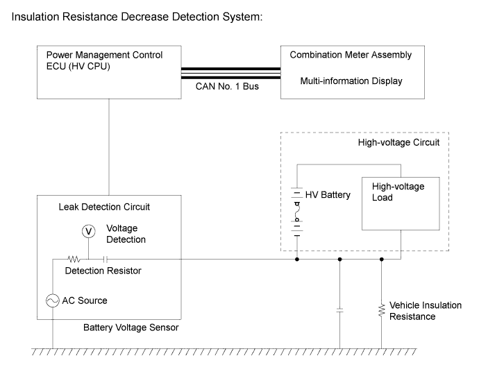
The "leak detection circuit", is built in the battery voltage sensor. The leak detection circuit constantly monitors that the insulation resistance between high-voltage circuits and body ground is maintained.
-
If the insulation resistance decreases below a specified level, a Diagnostic Trouble Code (DTC) is stored, and the driver was informed of the abnormality condition by the multi-information display.
-
The leak detection circuit has an AC source and it causes a small amount of AC to flow to the high-voltage circuit (positive and negative).
-
AC flows as shown in the following illustration. It flows via a detection resistor, a capacitor, and body ground.
-
The more vehicle insulation resistance decreases, the more voltage drops at the detection resistor and the lower the waves of AC. The insulation resistance value (Tester data name: Short Wave Highest Value) is detected based on the amplitude of AC waves.
-
-
Operating Condition of During Collision
-
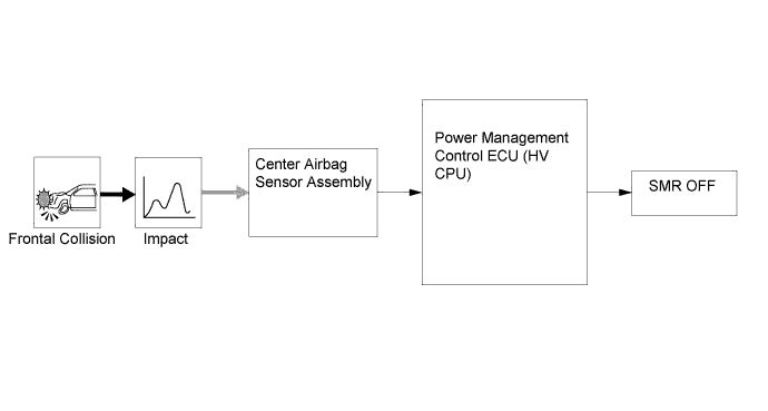
If the vehicle encounters one of the situations described below, the power management control ECU (HV CPU) will shut down the power supply by turning the System Main Relays (SMRs) off, for safety.
-
The power management control ECU (HV CPU) receives an airbag deployment signal from the center airbag sensor assembly during a frontal collision.
-
-
-
SYSTEM CONTROL
-
The LEXUS Hybrid Drive utilizes the following controls:
Item Outline Hybrid Vehicle Control
-
The power management control ECU (HV CPU) calculates the target motive force based on the shift lever position sensor, the degree to which the accelerator pedal is depressed, and the vehicle speed. It performs control in order to create the target motive force by optimally combining MG1, MG2, MGR, and the engine.
-
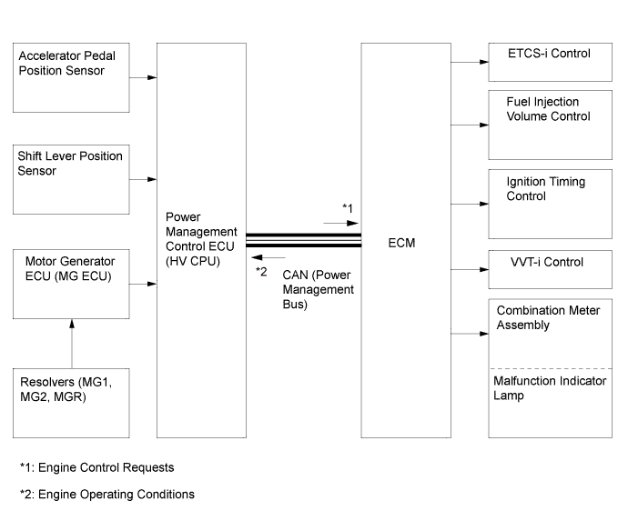
The power management control ECU (HV CPU) calculates the engine motive force based on the target motive force, which has been calculated based on the requirements of the driver and the conditions of the vehicle. In order to create this motive force, the power management control ECU (HV CPU) transmits signals to the ECM.
System Monitoring Control The power management control ECU (HV CPU) monitors the SOC of the HV battery and the temperature of the HV battery, MG1, MG2 and MGR, in order to optimally control these items. Shut Down Control When the shift lever is in the N position, the power management control ECU (HV CPU) performs shut down control to stop driving MG1, MG2 and MGR. System Main Relay (SMR) Control To ensure that it is possible to connect and disconnect the high voltage circuits reliably, the power management control ECU (HV CPU) controls the 3 SMRs to connect and disconnect the high voltage circuits from the HV battery. The power management control ECU (HV CPU) also uses the timing of the operation of the SMRs to monitor the operation of the relay contacts. State Of Charge (SOC) Control The power management control ECU (HV CPU) calculates the SOC by estimating the charging and discharging amperage of the HV battery. Cooling Fan Control The power management control ECU (HV CPU) uses temperature sensors in the HV battery to monitor the temperature of the HV battery. The power management control ECU (HV CPU) controls HV battery temperature by varying the speed of the 3 battery cooling blower assemblies that are provided. Auxiliary Battery Charging Control The power management control ECU (HV CPU) uses the battery temperature sensor in the auxiliary battery to monitor the temperature of the auxiliary battery. The power management control ECU (HV CPU) performs charge control based on temperature information from the auxiliary battery. ECM Control The ECM receives the target engine speed and required engine motive force, which were sent from the power management control ECU (HV CPU), and controls the Electronic Throttle Control System-intelligent (ETCS-i), fuel injection volume, ignition timing, and Variable Valve Timing-intelligent (VVT-i) system. MG1, MG2 and MGR Main Control
-
MG1, which is driven by the engine, generates high voltage (alternating current) in order to operate MG2 and charge the HV battery via the inverter. Also, MG1 functions as a starter to start the engine.
-
MG2, which is driven by electrical power from MG1 and/or the HV battery, generates motive force for the front wheels.
-
MGR, which is driven by the electrical power from MG1 and/or the HV battery, generates motive force for the rear wheels.
-
MG2 and MGR generate electricity to charge the HV battery (regenerative braking control) during braking, or when the accelerator pedal is not being depressed.
-
Resolvers detect the speed and the position of MG1, MG2, and MGR for use by the power management control ECU (HV CPU). Resolver signals are transmitted to the power management control ECU (HV CPU) via the Motor Generator ECU (MG ECU).
-
Temperature sensors mounted in MG1, MG2 and MGR detect the temperature for use by the power management control ECU (HV CPU).
Inverter with Converter Assembly Control
-
The inverter converts direct current from the HV battery into alternating current for MG1 and MG2, or vice versa, in accordance with the signals provided by the power management control ECU (HV CPU) via the Motor Generator ECU (MG ECU). In addition, the inverter is used to transfer power from MG1 to MG2.
-
Via the Motor Generator ECU (MG ECU), the power management control ECU (HV CPU) sends signals to the power transistors in the inverter for switching the U, V, and W phases of MG1, MG2, and MGR, in order to drive MG1 MG2 and MGR.
-
The power management control ECU (HV CPU) shuts down the inverter if it receives an overheat, over-current, or fault voltage signal from the inverter via the Motor Generator ECU (MG ECU).
Boost Converter Control
-
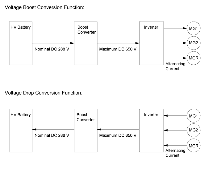
The boost converter boosts the nominal HV battery voltage of DC 288 V up to a maximum voltage of DC 650 V, in accordance with the signals provided by the power management control ECU (HV CPU) via the Motor Generator ECU (MG ECU).
-
The inverter converts the alternating current generated by MG1 MG2 or MGR into direct current. The boost converter drops the generated voltage of (up to 650V to approximately DC 288 V for the HV battery in accordance with the signals provided by the power management control ECU (HV CPU) via the Motor Generator ECU (MG ECU).
DC-DC Converter Control
-
Drops the voltage of DC 288 V (nominal) into DC 14 V (nominal) in order to supply electricity to body electrical components, as well as to recharge the auxiliary battery (DC 14 V).
-
This converter keeps the auxiliary battery at a constant voltage.
E-Four System Control E-Four system control calculates the torque distribution ratio of front and rear wheels based on various information from each sensor sent by the skid control ECU using its built-in AWD control. Skid Control ECU Control During braking, the skid control ECU calculates the required regenerative brake force and transmits it to the power management control ECU (HV CPU). Upon receiving this signal, the power management control ECU (HV CPU) transmits an actual regenerative brake control value to the skid control ECU. Based on this result, the skid control ECU calculates and executes the required hydraulic brake force. Battery Voltage Sensor Control The battery voltage sensor monitors the insulation of the high voltage electrical system for leakage. In addition, it converts the feedback signals of the cooling fan and the conditions of the HV battery and (which are needed by the power management control ECU (HV CPU) to perform SOC control and cooling fan control) into digital signals and transmits them to the power management control ECU (HV CPU). Shift Control The power management control ECU (HV CPU) detects the shift position (P, R, N, D, or S) in accordance with the signals provided by the shift lever position sensor. The power management control ECU (HV CPU) controls MG1, MG2, MGR and the engine to match the selected shift position. During Collision Control During a collision, if the power management control ECU (HV CPU) receives an airbag deployment signal from the center airbag sensor assembly, it turns the System Main Relay (SMRs) off in order to shut off the high voltage power supplied to the hybrid system by the HV battery. Cruise Control System Operation Control When the cruise control ECU that is enclosed in the power management control ECU (HV CPU) receives a cruise control switch signal, it regulates the hybrid system output to obtain the targeted vehicle speed based on the driver's demand. EV Mode Control When the EV drive mode switch is operated by the driver, the power management control ECU (HV CPU) uses only MG2 to drive the vehicle if the operating conditions are satisfied. Eco Drive Mode Control When the multi-information switch (steering pad switch assembly) is manually operated by the driver, the power management control ECU (HV CPU) moderates the response of the accelerator pedal operation to support Eco driving. Hybrid SNOW Mode Control When the multi-information switch (steering pad switch assembly) is manually operated by the driver, the power management control ECU (HV CPU) reduces the change in drive force in relation to the amount of accelerator operation to help secure drivability on slippery roads. SPORT Mode Control When the SPORT mode switch is operated by the driver, the power management control ECU (HV CPU) moderates the response of the accelerator pedal operation to optimize acceleration. Indicator and Warning Light Control Illuminates, blinks warning lights, or shows messages on the multi-information display to inform the driver of vehicle conditions or system malfunctions. -
-
Hybrid Vehicle Control
-
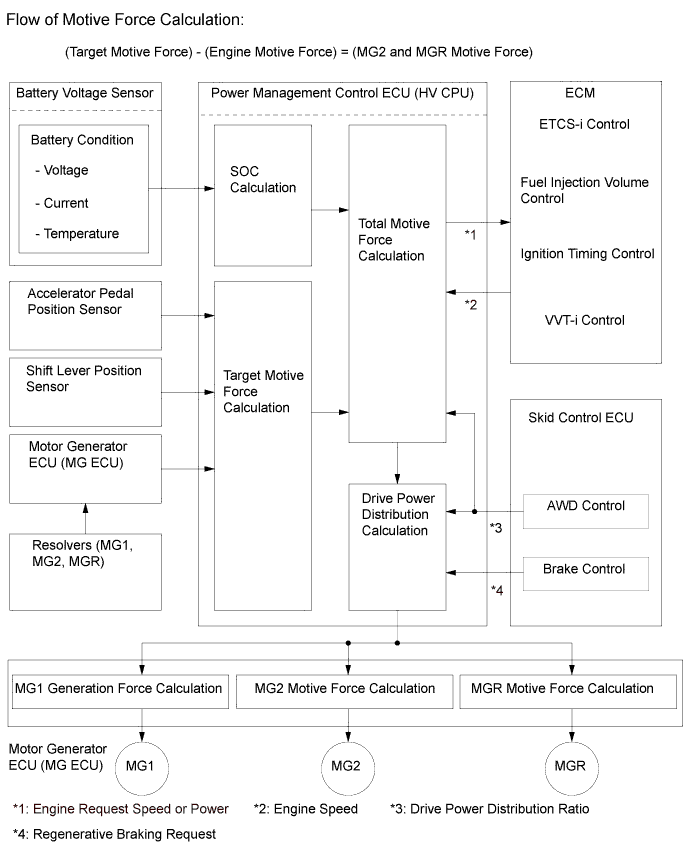
The power management control ECU (HV CPU) detects the amount of accelerator pedal depression using the signals from the accelerator pedal position sensor. The power management control ECU (HV CPU) receives vehicle speed signals from the MG2 resolver and detects the shift position signal from the shift lever position sensor. The power management control ECU (HV CPU) determines the vehicle operating conditions in accordance with this information, and optimally controls the motive forces of MG1, MG2, MGR and the engine. Furthermore, the power management control ECU (HV CPU) optimally controls the output and torque of MG1, MG2, MGR and the engine in order to realize lower fuel consumption and cleaner exhaust emissions.
-
The power management control ECU (HV CPU) calculates the engine motive force based on the calculated target motive force, and by taking the SOC and the temperature of the HV battery into consideration. The value obtained by subtracting the engine motive force from the target motive force is the MG2 and MGR motive force.
-
The ECM appropriately performs ETCS-i control, fuel injection volume control, ignition timing control, and VVT-i system control based on signals sent by the power management control ECU (HV CPU) in order to realize the required engine motive force. Furthermore, the power management control ECU (HV CPU) appropriately operates the MG1, MG2 and MGR in order to realize the required MG2 and MGR motive force.
-
-
System Monitoring Control
-
The power management control ECU (HV CPU) constantly monitors the State Of Charge (SOC) of the HV battery. When the SOC is below the lower level, the power management control ECU (HV CPU) increases the power output of the engine to operate MG1, which charges the HV battery. When the engine is stopped, MG1 operates to start the engine; then, the engine operates MG1 to charge the HV battery.
-
If the SOC is low, or the temperature of the HV battery, MG1, MG2 or MGR is higher than a specified value, the power management control ECU (HV CPU) restricts the motive force applied to the drive wheels until the value of the abnormal item returns to normal.
-
-
Shut Down Control
-
MG1 and MG2 are shut down when the shift lever is in the N position. This is because MG1 and MG2 must be stopped electrically as a means of shutting down the motive force, since MG2 is mechanically joined to the output shaft.
-
-
State of Charge Control
-
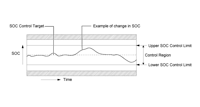
The power management control ECU (HV CPU) calculates the State Of Charge (SOC) of the HV battery by estimating its charging and discharging amperages, in order to control the SOC. This allows the hybrid system to make control decisions based on the power stored in the battery.
-
While the vehicle is in motion, the HV battery undergoes repetitive charge/discharge cycles, as it becomes discharged by MG2 or MGR during acceleration and charged by regenerative braking during deceleration. The power management control ECU (HV CPU) calculates the SOC based on the amount of HV battery charge/discharge detected by the current sensor. The power management control ECU (HV CPU) constantly performs charge/discharge control based on the calculated SOC value in order to maintain the SOC within its target range.
-
-
Cooling Fan Control
-
The power management control ECU (HV CPU) detects increases in battery temperature via the 6 temperature sensors in the HV battery. Then, the power management control ECU (HV CPU) steplessly actuates the battery cooling blower assemblies using duty cycle control, in order to maintain the temperature of the HV battery within the specified range.
-
While the air conditioning system is operating and cooling down the cabin, and if there is any leeway in the HV battery temperature, the power management control ECU (HV CPU) turns the battery cooling blower assemblies off or sets them to a low speed. The purpose of this control is to give priority to cooling down the cabin. If this control was not performed, air taken from the cabin for battery cooling would slow the cooling of the cabin by the air conditioning system.
-
-
ECM Control
-
The ECM receives the target engine speed and required engine motive force which were sent from the power management control ECU (HV CPU), and controls the ETCS-i system, fuel injection volume, ignition timing and VVT-i system.
-
The ECM transmits the operating condition of the engine to the power management control ECU (HV CPU).
-
Upon receiving an engine stop signal from the power management control ECU (HV CPU) in accordance with basic LEXUS Hybrid Drive control, the ECM will stop the engine.
-
When a malfunction occurs in the system, the ECM activates the Malfunction Indicator Lamp (MIL) via the directions from the power management control ECU (HV CPU).
-
-
MG1, MG2 and MGR Main Control
-
MG1, which is driven by the engine, generates high voltage (alternating current) in order to power MG2 and charge the HV battery. Also, MG1 functions as a starter to start the engine.
-
MG2 is driven by electrical power from MG1 or from the HV battery, and it generates motive force for the front wheels.
-
MGR is driven by electrical power from the HV battery and MG1, and it generates motive force for the rear wheels.
-
MG2 and MGR generate electricity to charge the HV battery (regenerative brake control) during braking, or when the accelerator pedal is not being depressed.
-
The Motor Generator ECU (MG ECU), which follows the commands of the power management control ECU (HV CPU), controls MG1, MG2, and MGR via the Power Modules (PMs), for driving the vehicle. 6 Insulated Gate Bipolar Transistors (IGBTs) switch on and off to control each individual motor generator in accordance with operation as either a motor or as a generator.
-
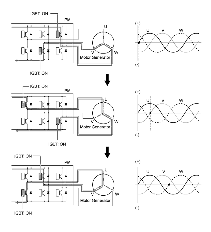
The illustration below describes the basic control when a motor generator functions as a motor.
-
The IGBTs switch on and off to supply three-phase alternating current to the motor.
-
In order to create the motive force required of the motor generator as calculated by the power management control ECU (HV CPU), the Motor Generator ECU (MG ECU) switches the IGBTs on and off and controls the speed, in order to control the speed of the motor generator.
-
-
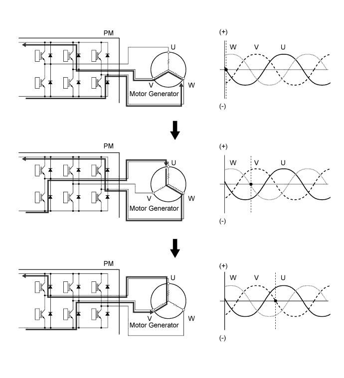
The illustration below describes the basic control used when a motor generator functions as a generator.
-
The current that is generated sequentially by the three phases of the motor, which is driven by the wheels, is utilized to charge the HV battery or drive another motor generator.
-
-
-
Inverter with Converter Assembly Control
-
The inverter converts the direct current from the HV battery into alternating current for MG1, MG2, and MGR, or vice versa, in accordance with the signals provided by the power management control ECU (HV CPU) via the Motor Generator ECU (MG ECU). In addition, the inverter takes power generated by MG1 and supplies it to MG2 or MGR. However, the electricity generated by MG1 is converted into DC inside the inverter before being converted back into AC by the inverter for use by MG2 or MGR. This is necessary because the frequency of the AC output by MG1 is not appropriate for control of MG2.
-
The Motor Generator ECU (MG ECU) transmits signals to the power transistors in the inverter for switching the U, V, and W phases of stator coils of MG1, MG2, and MGR based on the rotor position information sent by the MG1, MG2, and MGR resolvers.
-
When the shift lever is in the N position, or the power management control ECU (HV CPU) has received an over-heating, over-current, or fault voltage signal from the inverter, the power management control ECU (HV CPU) transmits a shut down control signal to the inverter, in order to turn off the power transistors to electrically disconnect MG1, MG2, and MGR.
-
-
Boost Converter Control
-
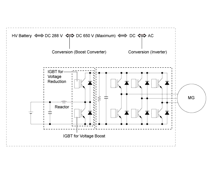
The boost converter boosts the HV battery voltage of DC 288 V (nominal) up to a maximum voltage of DC 650 V, in accordance with the signals provided by the power management control ECU (HV CPU) via the Motor Generator ECU (MG ECU).
-
The inverter converts the alternating current generated by MG1, MG2 or MGR into direct current. The boost converter drops the voltage of DC 650 V (maximum) to DC 288 V (nominal) for the HV battery in accordance with the signals provided by the power management control ECU (HV CPU) via the Motor Generator ECU (MG ECU).
-
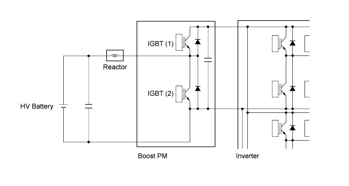
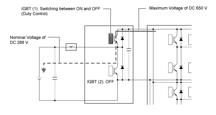
The boost converter consists of a boost Power Module (PM) with built-in IGBTs that perform switching control, and a reactor.
-
The reactor is an electronic component that has characteristics that resist changes in current flow. If a circuit containing a reactor is switched on and then off, the reactor will attempt to maintain current flow after being switched off. At the time of voltage reduction, these characteristics also assist in smoothing the output from the voltage drop IGBT (1). The reactor can be charged quickly by turning on the boost IGBT (2).
-
The boost converter boosts the HV battery voltage from DC 288 V (nominal) to a voltage of up to DC 650 V as described in the following 2 steps.
Step Outline 1 The IGBT (2) turns on, causing the electrical power of the HV battery (nominal voltage of DC 288 V) to charge the reactor. As a result, the reactor stores power. 2 The IGBT (2) turns off, causing the reactor to produce an electromotive force (the current continues to flow from the reactor). This electromotive force causes the voltage to rise to a maximum of DC 650 V. 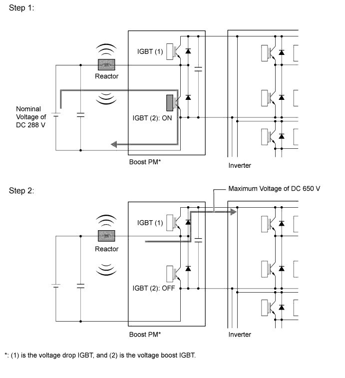
-
The alternating current which is generated by MG1, MG2 or MGR for the purpose of charging the HV battery is converted into direct current (maximum voltage approximately 650 V) by the inverter. Then, the boost converter is used to drop the voltage to approximately DC 288 V. This is accomplished by IGBT (1) being switched on and off using duty cycle control, intermittently interrupting the electrical power provided to the reactor by the inverter.
-
-
E-Four System Control
-
E-Four system control calculates an optimum front to rear torque distribution ratio based on the signals from various sensors and the power management control ECU (HV CPU).
-
E-Four system control is performed as follows according to each driving condition, achieving optimum start-off performance, driving stability and the effective use of energy.
Driving Condition Control Starting-off The skid control ECU calculates the total torque to be distributed to the front and rear wheels based on signals such as acceleration request drive torque or shift position signal sent from the power management control ECU (HV CPU). Based on the calculated total torque, the weight balance of the front and rear wheels and the best torque distribution in accordance with road conditions, signals are sent to the power management control ECU (HV CPU). Normal Driving Based on signals sent from the power management control ECU (HV CPU) such as acceleration request drive torque, shift position signal, speed sensors or steering angle sensor, the skid control ECU sends a signal indicating the optimum torque distribution for the front and rear wheels to the power management control ECU (HV CPU). Deceleration The skid control ECU evaluates signal inputs such as the acceleration drive torque or shift position signal, and then determines the amount of vehicle deceleration based on speed sensor readings sent from the power management control ECU (HV CPU). Based on this evaluation, the skid control ECU sends a regenerative braking request signal to the power management control ECU (HV CPU).
-
-
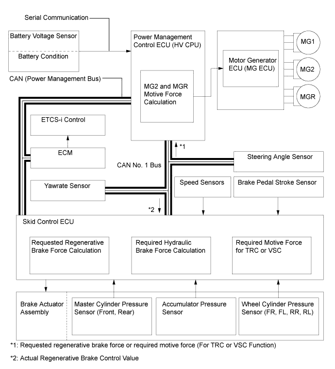
Skid Control ECU Control
-
The skid control ECU calculates the total braking force needed based on the master cylinder pressure in the brake actuator and brake pedal stroke sensor signal generated when the driver depresses the brake pedal.
-
After calculating the total brake force required, the skid control ECU sends a request to the power management control ECU (HV CPU). The power management control ECU (HV CPU) replies with the amount of regenerative brake force that is possible.
-
The power management control ECU (HV CPU) uses MG2 and MGR to create minus torque (deceleration force), thus carrying out the regenerative braking.
-
The skid control ECU controls the brake actuator solenoid valves and generates wheel cylinder pressure. The pressure that is generated is what remains after the actual regenerative brake control value has been subtracted from the total required braking force.
-
The skid control ECU outputs a request to the power management control ECU (HV CPU) to limit motive force while the VSC is operating to control wheel spin. The power management control ECU (HV CPU) controls the engine, MG1, MG2 and MGR in accordance with the present driving conditions in order to suppress the motive force.
-
-
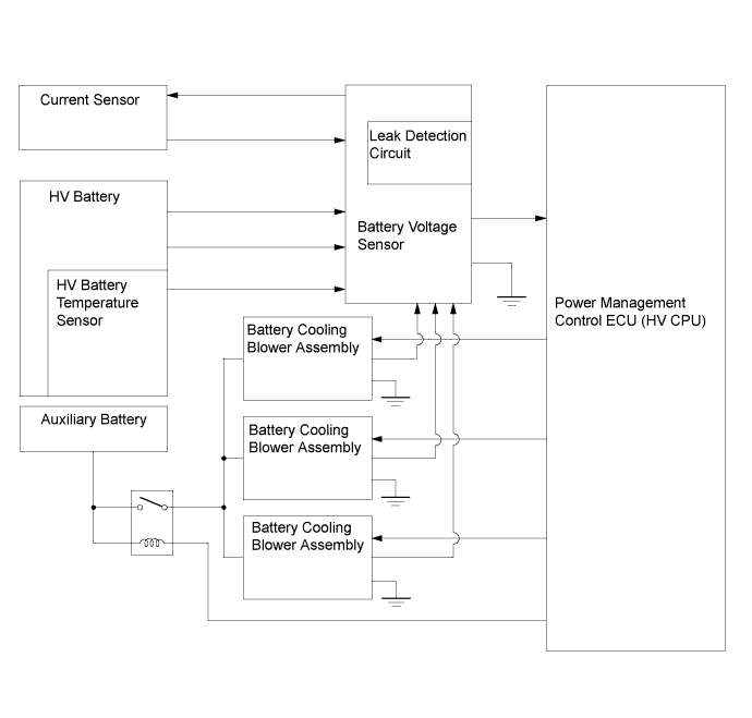
Battery Voltage Sensor Control
-
The battery voltage sensor converts the HV battery related signals (voltage, current, and temperature) into digital signals, and transmits them to the power management control ECU (HV CPU) via serial communication. These signals are needed to determine the charge or discharge values that are calculated by the power management control ECU (HV CPU).
-
A leakage detection circuit is provided in the battery voltage sensor in order to detect any electrical leakage from the HV battery or high voltage circuit. Also, the battery voltage sensor detects the feedback voltage from the battery cooling blower assemblies, which is needed by the power management control ECU (HV CPU) to perform cooling fan control. The battery voltage sensor converts these signals into digital signals and transmits them to the power management control ECU (HV CPU) via serial communication.
-
-
EV Mode Control
-
EV mode control allows the vehicle to be driven only using MG2 and MGR to reduce vehicle noise, such as when entering or leaving a garage after midnight, as well as reducing the production of exhaust in a garage.
-
The available driving range during the EV mode varies according to the driving conditions and the HV battery charge level. However, it is usually between several hundred meters (several hundred yards) and approximately 1 km (0.6 miles).
-
-
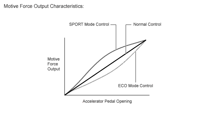
SPORT Mode and Eco Drive Mode Control
-
During SPORT mode, the power management control ECU (HV CPU) optimizes acceleration feel by increasing the power output more quickly at the beginning of accelerator pedal operation.
-
During ECO mode, the power management control ECU (HV CPU) optimizes fuel economy and driving performance by gently generating the motive force in comparison to accelerator pedal operation. At the same time, it supports Eco driving by optimizing the air conditioning performance.
-
-
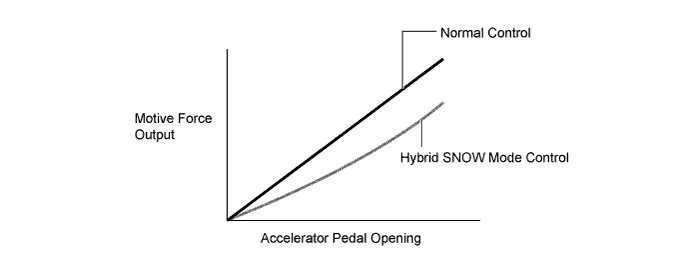
Hybrid SNOW Mode Control
-
When hybrid SNOW mode control is activated, the drive force that changes in accordance with the accelerator pedal operation is controlled to be smaller than normal around the accelerator pedal angle which causes the wheels to slip easily, achieving enhanced accelerator pedal controllability.
-
If the front wheels slip, assistance using MGR will be optimized to enhance start-off stability.
-
-
-
CONSTRUCTION
-
Motor Generator 1 (MG1), Motor Generator 2 (MG2), and Motor Generator Rear (MGR)
-
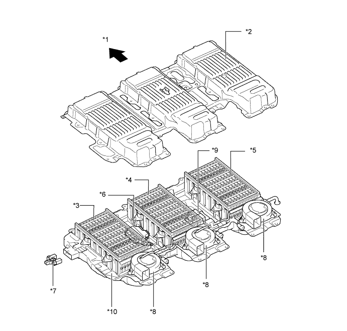
MG1, MG2, and MGR each consist of a stator, stator coil, rotor, permanent magnets, and resolver.
-
MG1, MG2, and MGR are compact, lightweight, and highly efficient alternating current permanent magnet motors.
-
MG1 charges the HV battery and supplies electrical power to drive MG2 and MGR. In addition, by regulating the amount of electrical power generated (thus varying the generator's rpm), MG1 effectively controls the continuously variable transmission function of the transaxle. MG1 also serves as the starter to start the engine.
-
MG2 drives the front wheels using electric power from MG1 or the HV battery. In addition, it acts as generator when decelerating to charge the HV battery.
-
MGR is provided in the rear drive unit. MGR, which is powered by electricity from MG1 or the HV battery, drives the rear wheels in accordance with the driving conditions, thus realizing excellent driving stability. During deceleration, MGR and MG2 function as generators, charging the HV battery as needed.
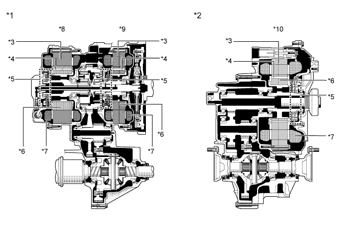
Text in Illustration *1 P313 Hybrid Transaxle (Hybrid Vehicle Transaxle Assembly) *2 Q211 Rear Drive Unit (Rear Traction Motor with Transaxle Assembly) *3 Stator *4 Permanent Magnet *5 Resolver *6 Rotor *7 Stator Coil *8 Motor Generator 2 (MG2) *9 Motor Generator 1 (MG1) *10 Motor Generator Rear (MGR) -
When a three-phase alternating current is passed through the three-phase windings of the stator coil, a rotating magnetic field is created in the electric motor. By controlling this rotating magnetic field according to the rotor's rotational position and speed, the permanent magnets that are provided in the rotor become attracted by the rotating magnetic field, thus generating torque.
-
The generated torque is for all practical purposes proportional to the amount of current, and the rotational speed is controlled by the frequency of the alternating current.
-
Furthermore, a high level of torque, all the way to high speeds, can be generated efficiently by properly controlling the relationship of the rotating magnetic field to the angle of the rotor magnets.
-
When the motor is used to generate electricity, the rotation of the rotor creates a rotating magnetic field, which creates current in the phases of the stator coils.
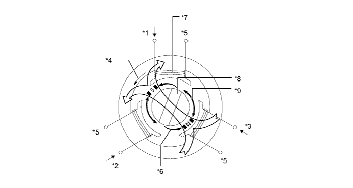
Text in Illustration *1 U Phase *2 V Phase *3 W Phase *4 Rotational Magnetic Field *5 Connected internally in the motor *6 Attraction *7 Stator Coil *8 Rotor *9 Repulsion - - 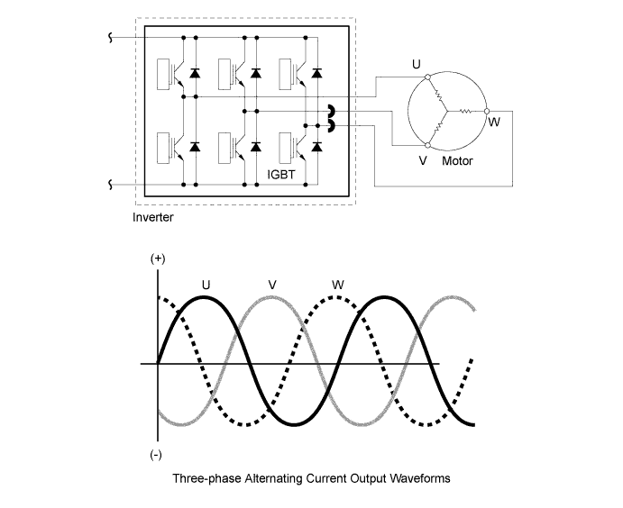
-
-
Resolver
-
A resolver is an extremely reliable and compact sensor that precisely detects the magnetic pole position. Knowing the precise position of the magnetic poles of the motor rotor is indispensable for ensuring efficient control of MG1, MG2 and MGR. MG1, MG2 and MGR each have their own resolver.
-
The stator of the resolver contains 3 types of coils: excitation coil A, detection coil S, and detection coil C.
-
The rotor of the resolver is oval, the distance of the gap between the stator and the rotor varies with the rotation of the rotor.
-
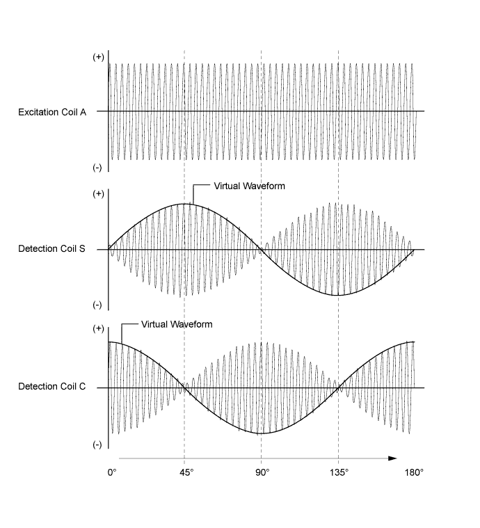
The flow of alternating current into excitation coil A results in the creation of a constant frequency magnetic field. Using this constant frequency magnetic field, coil S and coil C will output values that correspond to the position of the rotor. Therefore, the Motor Generator ECU (MG ECU) detects the absolute position based on the difference between the coil S and coil C output values. Furthermore, the Motor Generator ECU (MG ECU) calculates the rotational speed based on the amount of change in the position within a given length of time.
-
The +S and -S pairs of the S detection coil are staggered by 90 degrees. The +C and -C pairs are also staggered in the same way. The C and S pairs of coils are located 45 degrees from each other.
-
The detection coils have an electrical orientation as shown below.
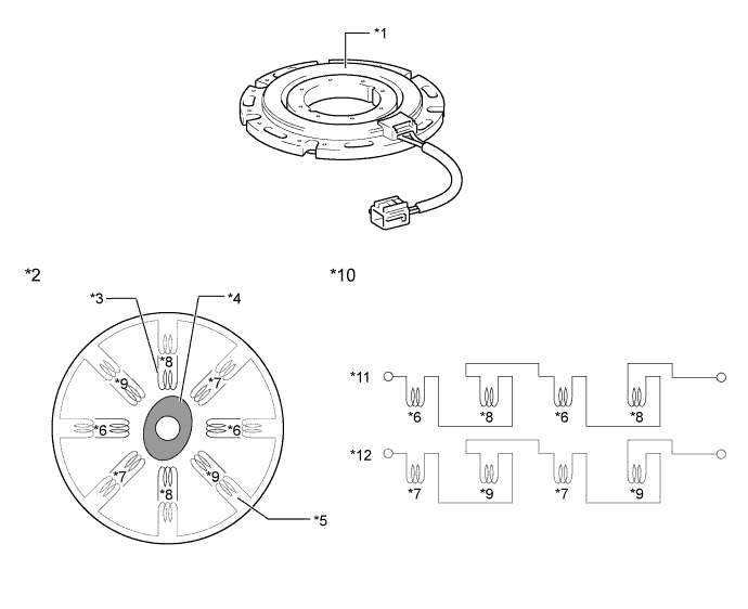
Text in Illustration *1 Resolver *2 Image of Resolver Internal Construction *3 Detection Coil *4 Rotor *5 Excitation Coil (Coil A) *6 +S *7 +C *8 -S *9 -C *10 Electrical Orientation of Resolver Coils *11 Coil S *12 Coil C -
Because the excitation coil of the resolver is provided with alternating current at a constant frequency, a constant frequency magnetic field is output to coils S and C, regardless of rotor speed. The magnetic field of the excitation coil is carried to coils S and C by the rotor. The rotor is oval, and the gap between the stator of the resolver and the its rotor varies with the rotation of the rotor. Due to the variation of the gap, the peak values of the waveforms output by coils S and C vary in accordance with the position of the rotor.
-
The Motor Generator ECU (MG ECU) constantly monitors these peak values, and connects them to form a virtual waveform. The Motor Generator ECU (MG ECU) calculates the absolute position of the rotor from the difference between the values of the coils S and C. It determines the rotor direction based on the difference between the phases of the virtual waveform of the coil S and the virtual waveform of the coil C. Furthermore, the Motor Generator ECU (MG ECU) calculates the rotational speed based on the amount of change in the rotor position within a given length of time.
-
The diagrams below illustrate the waveforms that are output at coils A, S, and C when the rotor makes a rotation of 180°.
-
-
Temperature Sensor
-
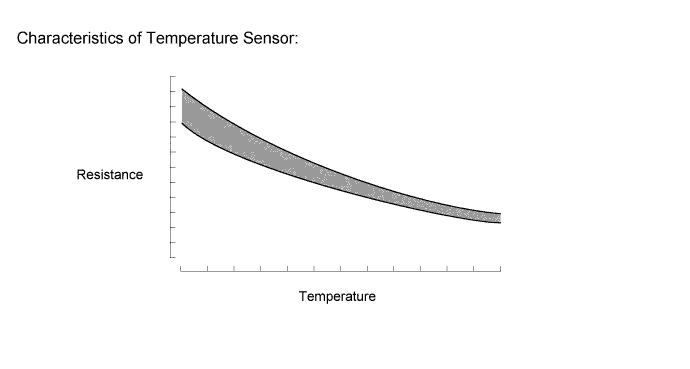
Temperature sensors are used to detect the temperature of the motor stators.
-
The temperature sensor thermistor resistance changes according to the change of motor temperature. The resistance of the thermistor is high when the temperature of the motor is low. Conversely, when the motor temperature is high, the thermistor resistance will be low.
-
When the temperature of a motor rises, motor output is limited.
-
-
Inverter with Converter Assembly
-
The inverter with converter assembly has a multi-layer structure which consists of the Motor Generator ECU (MG ECU), inverter, boost converter, condenser and DC-DC converter, achieving a lightweight and compact design.
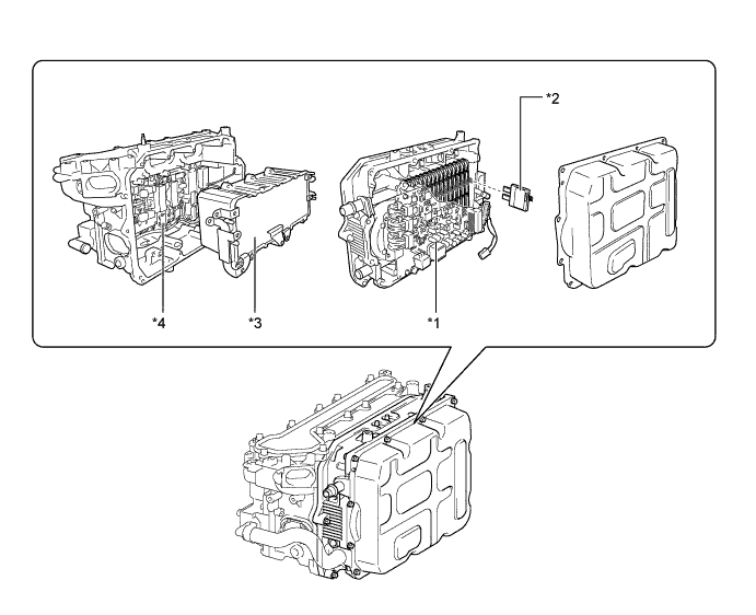
Text in Illustration *1 Control Circuit Portion
- Motor Generator ECU (MG ECU)
- Inverter
- Boost Converter
*2 IGBT *3 Condenser *4 DC-DC Converter Portion -
The inverter with converter assembly is cooled by the dedicated radiator of a cooling system that is separate from that of the engine cooling system.
-
This inverter has a cooling system with a structure that makes it possible to cool the IGBTs of the boost converter and inverter from both sides, contributing to a compact design.
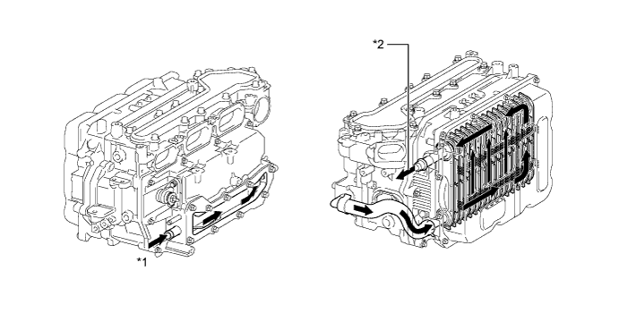
Text in Illustration *1 Coolant Inlet *2 Coolant Outlet 
Coolant Flow - - -
In consideration of safety, interlock switches are provided for the inverter with converter assembly. The interlock switches turn off the System Main Relays (SMRs) when the inverter terminal cover is removed or the connector of the HV battery power cable is disconnected.
-
An atmospheric pressure sensor is provided on the Motor Generator ECU (MG ECU) board. The sensor detects atmospheric pressure and transmits a signal to the Motor Generator ECU (MG ECU) to allow corrections that correspond to the usage environment.
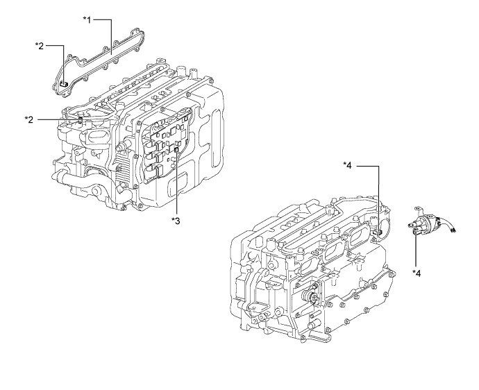
Text in Illustration *1 Inverter Terminal Cover *2 Interlock Switch (For Inverter Terminal Cover) *3 Atmospheric Pressure Sensor *4 Interlock Switch (For Power Cable) 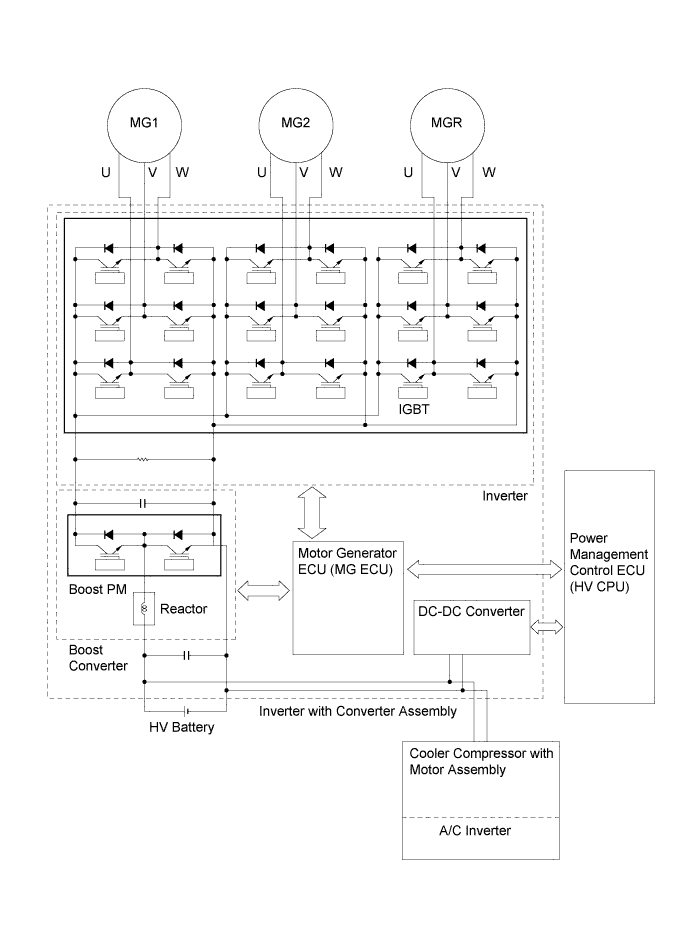
-
-
Inverter
-
The inverter converts the boosted high-voltage direct current of the HV battery into three-phase alternating current to drive MG1, MG2 and MGR.
-
The activation of the power transistors is controlled by the Motor Generator ECU (MG ECU). In addition, the inverter transmits information that is needed for current control, such as the output amperage or voltage, to the power management control ECU (HV CPU) via the Motor Generator ECU (MG ECU).
-
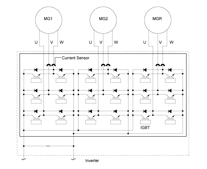
The power transistors used in the inverter are Insulated Gate Bipolar Transistors (IGBTs).
-
Each of the bridge circuits for MG1, MG2, and MGR contains 6 IGBTs, mounted on the high voltage, high current module portion of a Power Module (PM). In addition, a signal processor/protective function processor has been integrated into control portion of the PM. The PM is used to operate the power transistors based on signals from the Motor Generator ECU (MG ECU).
-
-
Boost Converter
-
The boost converter boosts the nominal voltage of DC 288 V that is output by the HV battery to a maximum voltage of DC 650 V. The boost converter consists of the boost Power Module (PM) with a pair of built-in IGBTs which perform switching control, and a reactor which acts as an inductor. By using these components, the converter boosts the voltage.
-
When MG1, MG2 or MGR acts as a generator, the inverter converts the alternating current (maximum voltage of 650 V) into DC, and then the boost converter reduces the voltage to a nominal voltage of DC 288 V, thus the HV battery is charged.
-
-
DC-DC Converter
-
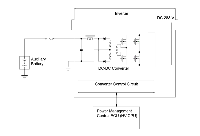
The power source for auxiliary equipment of the vehicle such as the lights, audio system, and the air conditioning system (except the cooler compressor with motor assembly), as well as the ECUs, is based on a DC 14 V system. Because the LEXUS Hybrid Drive generates output with a nominal voltage of DC 288 V, the DC-DC converter is used to transform the voltage from DC 288 V to approximately DC 14 V in order to recharge the auxiliary battery.
-
-
Motor Generator ECU (MG ECU)
-
The Motor Generator ECU (MG ECU) is provided in the inverter with converter assembly. In accordance with signals received from the power management control ECU (HV CPU), the Motor Generator ECU (MG ECU) controls the inverter and boost converter in order to drive MG1, MG2, or MGR or to cause them to generate electricity.
-
The Motor Generator ECU (MG ECU) transmits information that is required for vehicle control, such as the inverter output amperage, inverter temperature, and failure information, to the power management control ECU (HV CPU). It receives information that is required for controlling the motor generators, such as the required motive force or the motor temperature, from the power management control ECU (HV CPU).
-
-
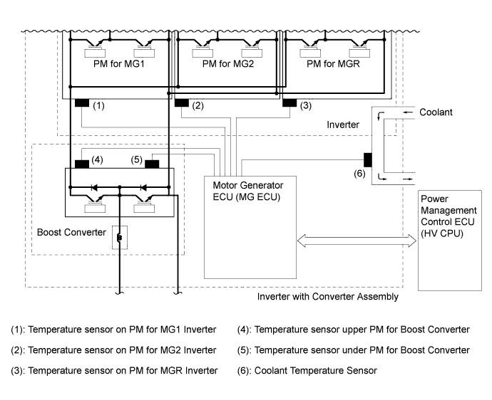
Temperature Sensors
-
In the inverter with converter assembly, there are 6 different temperature sensors, there is a sensor for the coolant temperature, 2 for the boost converter and one each for the PMs for MG1, MG2 and MGR. The Motor Generator ECU (MG ECU) confirms the effectiveness of the inverter cooling system based on the temperature information sent from these sensors. In addition, inverter output is limited when the temperature is high.
-
-
Current Sensor for Motor Generator
-
For the 3-phase AC used to drive MG1, MG2 and MGR, there are current sensors for the V and W phases. The actual current value is measured, and used as feedback by the Motor Generator ECU (MG ECU).
-
If the current value of 2 phases (V and W phases) is measured, the current of the U phase can be determined, even though it is not equipped with a current sensor. (U phase current + V phase current + W phase current = 0)
-
-
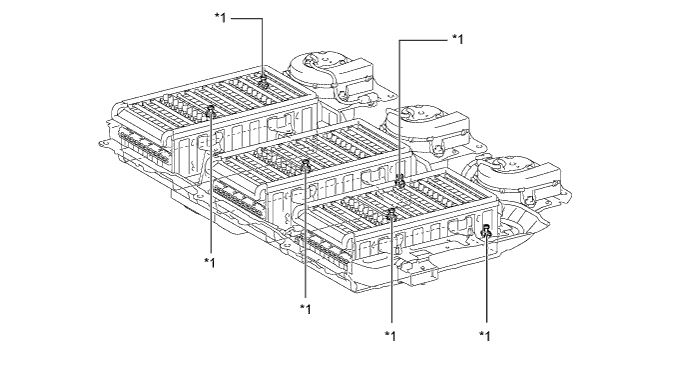
HV Battery Assembly
-
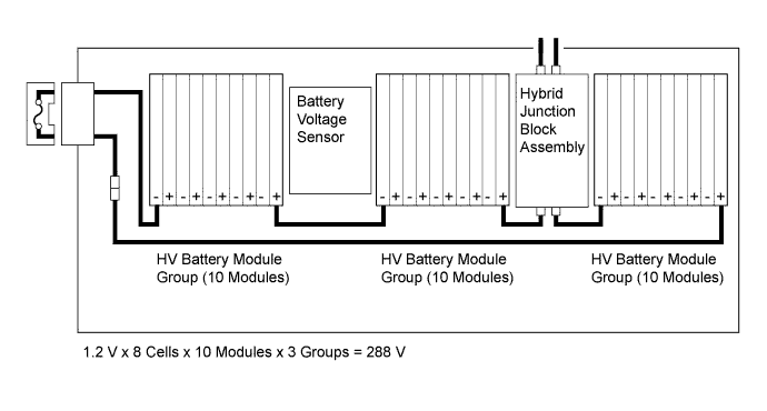
The HV battery assembly consists of the upper cover, 3 HV battery module groups, 3 battery cooling blower assemblies, junction connector, battery voltage sensor and service plug grip.
-
The cooling fan operation of the HV battery assembly is controlled to ensure the proper performance by the power management control ECU (HV CPU). The cooling fan control is required because the HV battery assembly creates heat while it is being charged and discharged. One cooling fan is provided for each of the 3 groups of the HV battery assembly. The cooling system uses air from the cabin.
-
A service plug grip is provided to shut off the internal circuit of the battery.
Text in Illustration *1 Front *2 Upper Battery Case *3 HV Battery Module Group (LH) *4 HV Battery Module Group (Center) *5 HV Battery Module Group (RH) *6 Battery Voltage Sensor *7 Service Plug Grip *8 Battery Cooling Blower Assembly *9 Hybrid Junction Block Assembly *10 Lower Battery Case
-
-
HV Battery Module Group
-
The HV battery module groups are split into 3 separate groups inside the battery case.
-
Metal is used for the material of the module cases to realize enhanced cooling performance and compact construction.
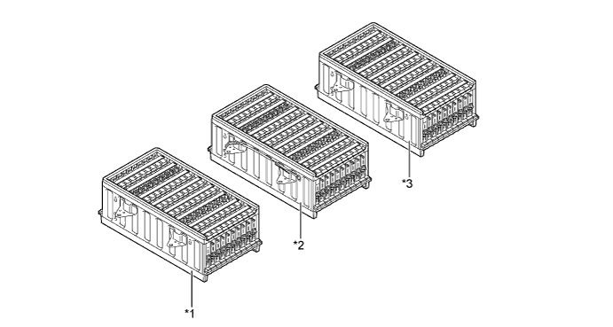
Text in Illustration *1 HV Battery Module Group (LH) *2 HV Battery Module Group (Center) *3 HV Battery Module Group (RH) - - -
Each HV battery module group consists of 10 modules that are connected in series by a bus bar module. Furthermore, the connection between cells is made at 2 locations in order to reduce internal resistance and improve efficiency.
-
1 module consists of 8 cells. 1 cell is 1.2 V.
-
-
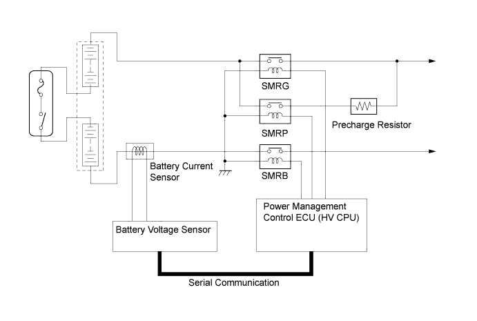
Hybrid Junction Block Assembly
-
Hybrid junction block assembly consists of the System Main Relays (SMRs), precharge resistor and an HV battery current sensor.
-
The SMRs consist of the SMRB (+), SMRG (-) and SMRP (precharge).
-
A large amount of current is generated due to the connection of the power cables. As a result, SMRP and SMRB (+) are turned on first to let the current enter the circuit in a controlled manner through the precharge resistor to protect the circuit. After that, the SMRG is turned on and SMRP is turned off.
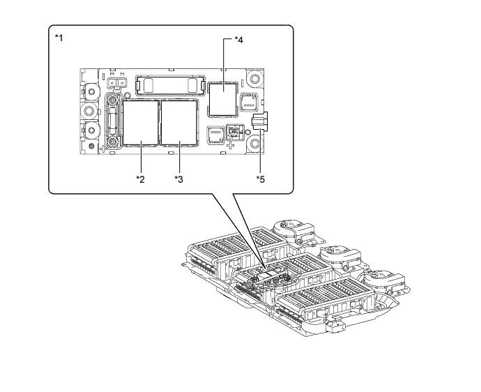
Text in Illustration *1 Hybrid Junction Block Assembly *2 SMRB (+) *3 SMRG (-) *4 SMRP (Precharge) *5 HV Battery Current Sensor - -
-
-
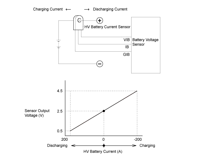
HV Battery Current Sensor
-
The HV battery current sensor is installed on the high-voltage cable inside the HV battery assembly, to detect current flow. It sends a voltage signal to the battery voltage sensor. This signal changes between 0.5 and 4.5 V in proportion to changes in the current flowing to or from the HV battery assembly. Less than 2.5 V means the HV battery assembly is being discharged, and more than 2.5 V means the HV battery assembly is being charged.
-
-
Service Plug Grip
-
By removing the service plug grip before performing any inspection or service, the high-voltage circuit is opened in the middle of the HV battery assembly, for safety during service.
-
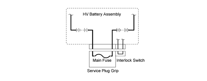
The main fuse for the high-voltage circuit and the interlock switch are provided inside of the service plug grip.
-
For further details on how to handle the service plug grip and for other safety cautions, refer to the Repair Manual.
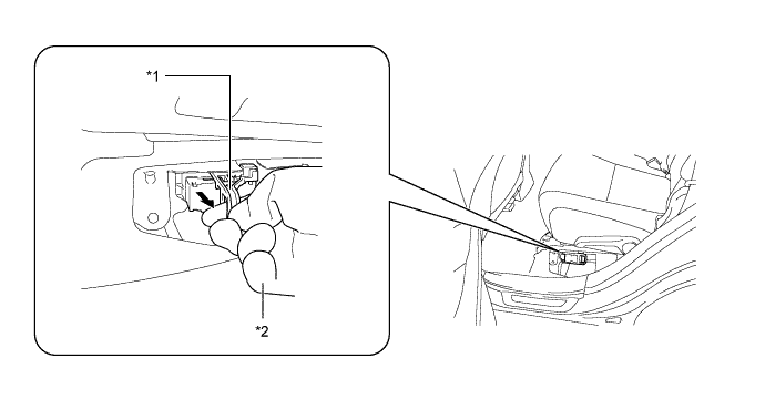
Text in Illustration *1 Service Plug Grip *2 Insulated Glove -
The main fuse is connected between module No. 10 and module No. 11 in the HV battery. When the service plug grip is removed, it interrupts the circuit for the HV battery. Before servicing any portion of the high-voltage circuit, make sure to turn the power switch off before removing the service plug grip.
-
-
Battery Temperature Sensor
-
The battery temperature sensor resistance changes along with the temperature change of the HV battery assembly.
-
The battery voltage sensor transmits the detection results of the battery temperature sensors to the power management control ECU (HV CPU) which then controls the battery cooling blower assemblies.
Text in Illustration *1 Battery Temperature Sensor
-
-
HV Radiator
-
The HV radiator and engine radiator are separate parts.
-
-
Inverter Water Pump (Water Pump with Motor Assembly)
-
A compact and high output type electric water pump is used.
-
A high output DC motor (brushless type) is used for the pump motor, furthermore, bearings that support the motor shaft at both ends are employed, thus suppressing noise and vibration.
-
The inverter water pump (water with motor pump assembly) is controlled to 3 stages by the power management control ECU (HV CPU) according to inverter coolant temperature in order to cool the inverter.
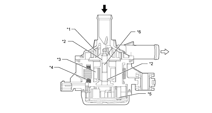
Text in Illustration *1 Impeller *2 Bearing *3 Magnet *4 Coil *5 Motor Controller *6 Shaft HV Coolant Inlet 
HV Coolant Outlet
-
-
Power Cable
-
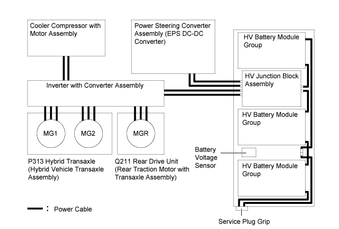
The power cable is a set of high-voltage, high-amperage cables that connect the HV battery with the inverter with converter assembly, the HV battery with the power steering converter assembly (EPS DC-DC converter), the inverter with converter assembly with MG1, MG2 and MGR and the inverter with converter assembly with the cooler compressor with motor assembly.
-
The power cable is made of shielded cables in order to reduce electromagnetic interference.
-
For identification purposes, the high-voltage wiring harness and connectors are color-coded orange to distinguish them from those of the ordinary low-voltage wiring.
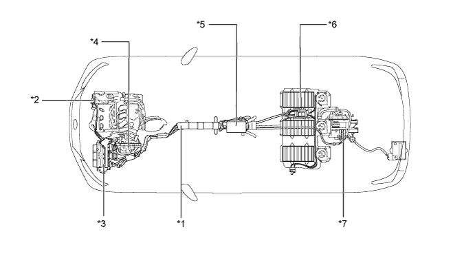
Text in Illustration *1 Power Cable *2 Cooler Compressor with Motor Assembly *3 Inverter with Converter Assembly *4 P313 Hybrid Transaxle (Hybrid Vehicle Transaxle Assembly)
- MG1
- MG2
*5 Power Steering Converter Assembly (EPS DC-DC Converter) *6 HV Battery *7 Q211 Rear Drive Unit (Rear Traction Motor with Transaxle Assembly)
- MGR
- - 
-
-
Acceleration Pedal Position Sensor
-
The non-contact type accelerator pedal position sensor uses a Hall IC which is mounted on the accelerator pedal arm.
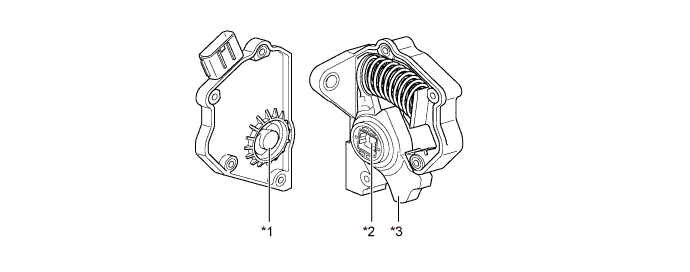
Text in Illustration *1 Hall IC *2 Magnetic Yoke *3 Accelerator Pedal Arm - - -
A magnetic yoke is mounted at the base of the accelerator pedal arm. This yoke rotates around the Hall IC in accordance with the amount of effort that is applied to the accelerator pedal. The Hall IC converts the changes in the magnetic flux that occur into electrical signals, and outputs accelerator pedal position signals to the power management control ECU (HV CPU).
-
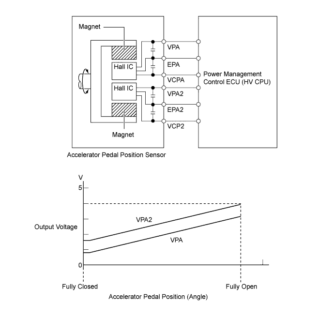
The Hall IC contains 2 circuits, one for the main signal, and one for the sub signal. It converts the accelerator pedal position (angle) into electric signals that have differing characteristics and outputs them to the power management control ECU (HV CPU).
-
-
Auxiliary Battery Temperature Sensor
-
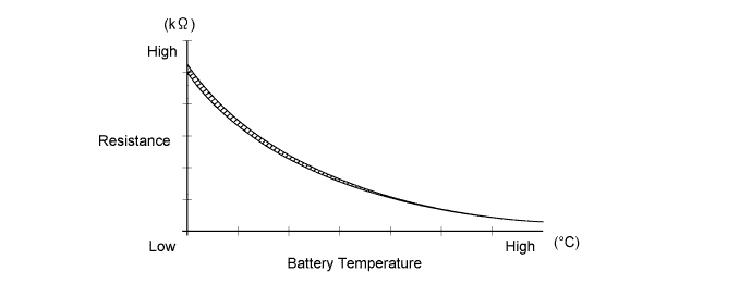
The battery characteristic (battery internal resistance) of taking in current for charging varies according to battery electrolyte temperature. If the battery electrolyte temperature is too low or too high, the battery will degrade more quickly, resulting in premature failure.
-
To prevent this, the auxiliary battery temperature sensor resistance changes as shown below to allow the power management control ECU (HV CPU) to detect the auxiliary battery temperature.
-
-
Multi-information Switch (Steering Pad Switch Assembly)
-
The multi-information switch (steering pad switch assembly) can select from EV mode, ECO drive mode and hybrid SNOW mode.
-
When the menu switch is pushed on the multi-information switch (steering pad switch assembly), the multi-information display will change to electronic features control mode. The desired switch can be selected by pressing the ENTER switch upward or downward.
-
The selected switch can be turned on or off by pressing in the ENTER switch.
-
-
Combination Meter Assembly
-
The combination meter assembly informs the driver of the LEXUS Hybrid Drive conditions using the READY indicator light, hybrid SNOW indicator light, ECO driving mode indicator light, EV mode indicator light, Malfunction Indicator Lamp (MIL), discharge warning light and multi-information display.
-
The multi-information display shows messages according to instructions from the power management control ECU (HV CPU) to inform the driver when a malfunction occurs or EV mode is entered.
-
The master warning light may illuminate or flash and the buzzer built into the combination meter may sound depending on the message displayed on the multi-information display.
Message Message Content Explanation Master Warning Light Buzzer FWD MAINTENANCE MODE FWD inspection mode is in use. - - AWD MAINTENANCE MODE AWD inspection mode is in use. - - FWD CERTIFICATION MODE FWD certification mode is in use. - - AWD CERTIFICATION MODE AWD certification mode is in use. - - SHIFT TO P RANGE WHEN PARKED The vehicle is in the READY-ON mode, the shift position is in the N, D, or S position, and the driver's door is opened. Flashes - LOW TRACTION BATTERY SHIFT TO P RANGE SOC drops below a predetermined value (SOC 18% or lower) Flashes - SOC drops below a predetermined value (SOC 25% or lower) Flashes - N POSITION Indicates that the accelerator pedal is being depressed while the shift lever is in N. Flashes - CHECK HYBRID SYSTEM LEXUS Hybrid Drive is malfunctioning Illuminates Sounds SHIFT TO P RANGE TO START The shift lever is moved into any position other than P while the READY indicator is flashing. Flashes Sounds HYBRID SYSTEM OVERHEAT The temperatures of any parts related to the LEXUS Hybrid Drive exceed the standard value. Illuminates Sounds EV MODE NOT AVAILABLE WARMING UP The hybrid system is warming up. - - EV MODE NOT AVAILABLE LOW BATTERY EV mode is not available because the HV battery SOC is low. - - EV MODE NOT AVAILABLE EXCESSIVE SPEED EV mode is not available because the vehicle speed is greater than the specified EV mode speed. - - EV MODE NOT AVAILABLE EXCESSIVE ACCELERATION EV mode is not available because the accelerator pedal depression amount exceeds the specified value. - - EV MODE CURRENTLY NOT AVAILABLE EV mode is not available because other conditions have not been met. - - EV MODE DEACTIVATED LOW BATTERY EV mode is deactivated because hybrid battery SOC is low. - - EV MODE DEACTIVATED EXCESSIVE SPEED EV mode is deactivated because the vehicle speed exceeds the specified EV mode speed. - - EV MODE DEACTIVATED EXCESSIVE ACCELERATION EV mode is deactivated because the accelerator pedal depression amount exceeds the specified value. - - EV MODE DEACTIVATED EV mode is deactivated because the vehicle no longer satisfies EV mode operating conditions. - -
-
-
Energy Monitor
-
The energy monitor can be shown on the multi-information display or multi display.
-
The energy monitor also shows the energy flow in the form of an arrow, and shows the State Of Charge (SOC) of the HV battery in 0 to 8 levels.
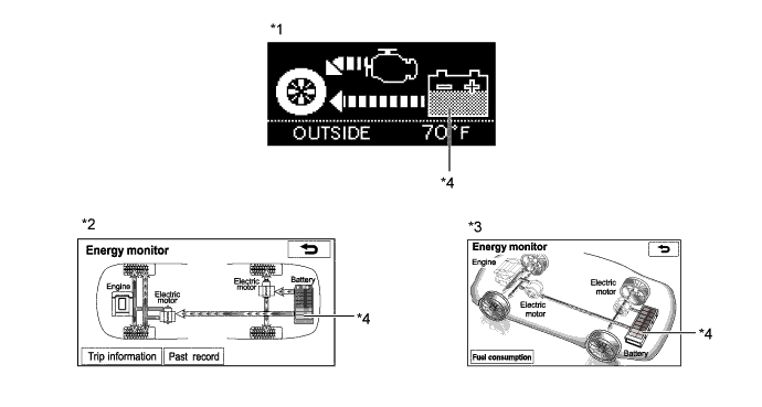
Text in Illustration *1 Multi-information Display: *2 Lexus Display Audio System *3 HDD Navigation System *4 SOC Level Display
-
-
-
OPERATION
-
How to Read a Nomographic Chart
-
The nomographic chart below gives a visual representation of the power split planetary gear unit rotation direction, rotational speed, and torque balance.
-
In the nomographic chart, a straight line is used to represent the relationship between the rotational speeds of the 3 gears in the power split planetary gear unit. The rotational speed of each gear is indicated by the distance from the 0 rpm point. Due to the structure of the power split planetary gear unit, the relationship between the rotational speeds of the 3 gears is always expressed by a straight line.
-
The relationship between the gear rotation directions and the torque that acts on each gear is as described below.
-
In the following illustrations, the terms "drive" and "driven" are used for MG1, MG2, MGR and the engine. Depending on system operation, the term drive or driven is used to identify whether the device is being mechanically driven by something else, or whether it is driving something mechanically. In other words, when "MG2 (driven)" is written, MG2 is operating as a generator. When "MG2 (drive)" is written, MG2 is operating as a motor.
-
Due to the structure of this hybrid transaxle, the MG2 motive force acts on the ring gear via the motor speed reduction planetary gear unit. This is represented by the solid line that extends to the right side of the central vertical ring gear line.
-
The nomographic charts and the illustrations of the power split planetary gear unit operation for each vehicle running condition shown on the following pages are examples only. The examples shown are 'snapshots', normal system operation is a constantly changing blend of conditions and system reactions to suit those conditions.
-
-
Torque and Rotation Relationship
-
For the hybrid system, motor generators have different roles depending on the situation. Understanding the relationship between rotation direction and torque can help to make the role of a motor generator easier to understand.
-
The table below shows the relationship of drive and electric generation for different combinations of plus or minus torque and forward or reverse rotation.
Rotation Plus Torque Minus Torque Forward (+) Rotation Drive Electric Generation Reverse (-) Rotation Electric Generation Drive -
As an example, if a motor generator is rotating in the forward (+) direction, and it applies minus torque, it will generate electricity (producing electrical power).
-
Alternately, if the motor generator is rotating in the reverse (-) direction and it applies minus torque, it will act as a drive source (consuming electrical power).
-
-
READY ON State
-
Even if the driver turns the power switch on (READY), sometimes the engine will not start. If this happens, the engine, MG1, MG2 and MGR remain stopped. The engine will only start if conditions such as engine coolant temperature, HV battery State Of Charge (SOC), HV battery temperature, and electrical load require an engine start.
-
After driving, if the driver stops the vehicle and moves the shift lever to P, the power management control ECU (HV CPU) will continue to operate the engine. The engine will continue to operate until SOC, engine coolant temperature, battery temperature and/or electrical load conditions reach a specified level.
-
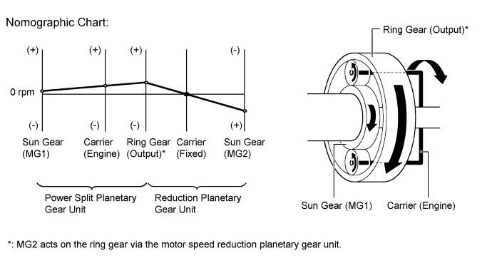
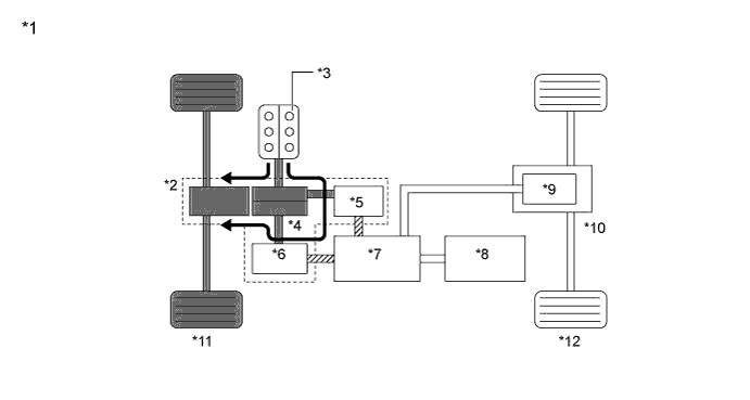
If any of the items monitored by the power management control ECU (HV CPU) indicates the need for an engine start when the READY indicator is on and the shift lever is in P, the power management control ECU (HV CPU) will activate MG1 to start the engine.
-
While the engine is cranking, to prevent the reactive force of the sun gear of MG1 from rotating the ring gear and driving the drive wheels, current is also applied to MG2 in order to prevent MG2 from rotating. This function is called "reactive control".
Text in Illustration *1 Engine Starting: *2 P313 Hybrid Transaxle (Hybrid Vehicle Transaxle Assembly) *3 Engine (Driven) *4 Compound Gear Unit *5 MG1 (Drive) *6 MG2 *7 Inverter *8 HV Battery *9 MGR *10 Q211 Rear Drive Unit (Rear Traction Motor with Transaxle Assembly) *11 Front Wheels *12 Rear Wheels 
Electrical Path 
Mechanical Power Path Power Transmission - - 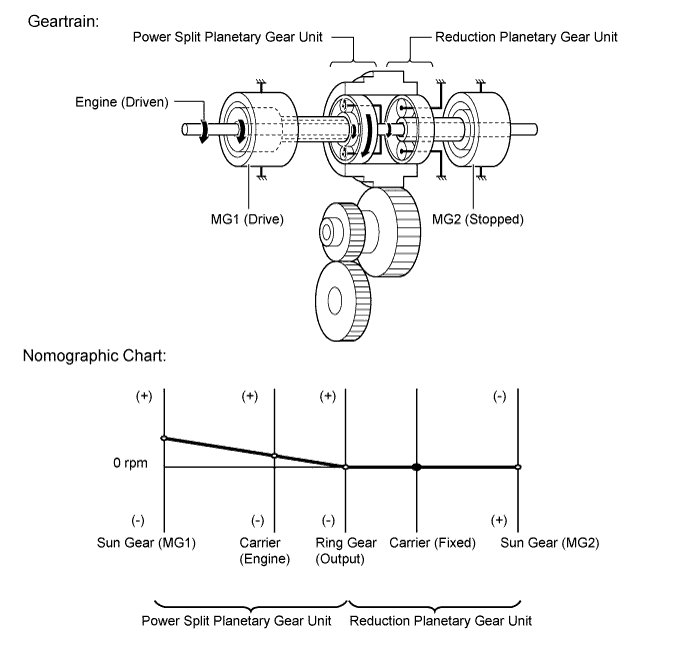
-
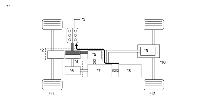
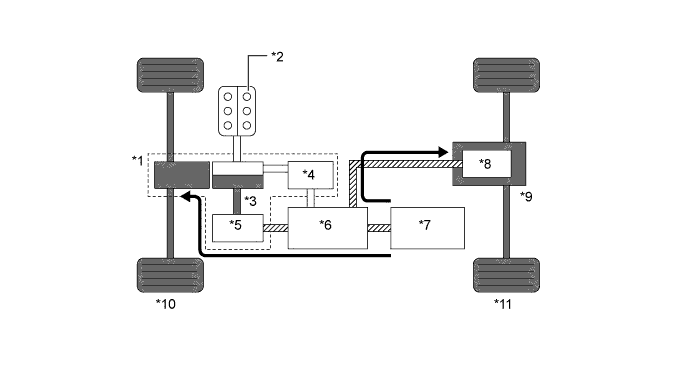
If the SOC of the HV battery is low, it is charged by MG1 which is driven by the engine.
Text in Illustration *1 Charging HV Battery: *2 P313 Hybrid Transaxle (Hybrid Vehicle Transaxle Assembly) *3 Engine (Drive) *4 Compound Gear Unit *5 MG1 (Driven) *6 MG2 *7 Inverter *8 HV Battery (Charged by power from MG1) *9 MGR *10 Q211 Rear Drive Unit (Rear Traction Motor with Transaxle Assembly) *11 Front Wheels *12 Rear Wheels Electrical Path Mechanical Power Path Power Transmission - - 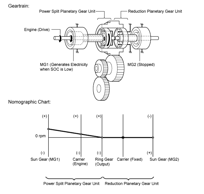
-
-
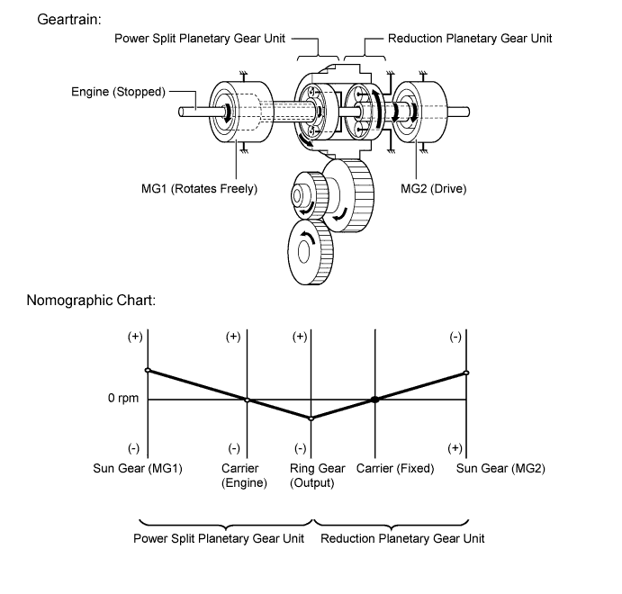
Starting Off
-
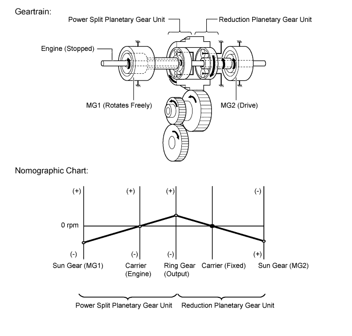
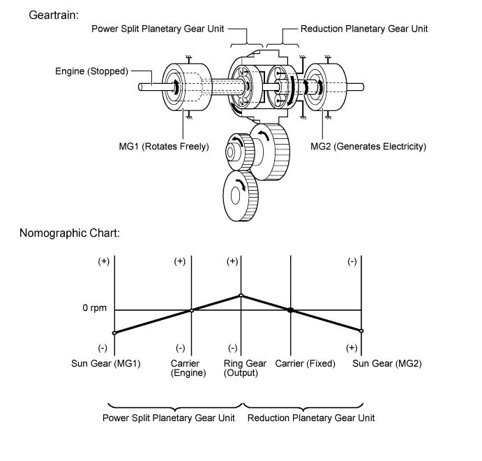
When the vehicle is started off, the vehicle operates powered by MG2 and MGR.
Text in Illustration *1 P313 Hybrid Transaxle (Hybrid Vehicle Transaxle Assembly) *2 Engine (Stopped) *3 Compound Gear Unit *4 MG1 (Rotates Freely) *5 MG2 (Drive) *6 Inverter *7 HV Battery *8 MGR (Drive) *9 Q211 Rear Drive Unit (Rear Traction Motor with Transaxle Assembly) *10 Front Wheels *11 Rear Wheels Electrical Path Mechanical Power Path Power Transmission -
When the vehicle starts off under normal conditions, it runs using the motive force of MG2 and MGR. While running under this condition, the rotational speed of the carrier is 0 rpm due to the engine being stopped. In addition, since MG1 does not generate any torque, no torque acts on the sun gear. However, the sun gear rotates freely in the (-) direction balancing the rotating ring gear (Output).
-
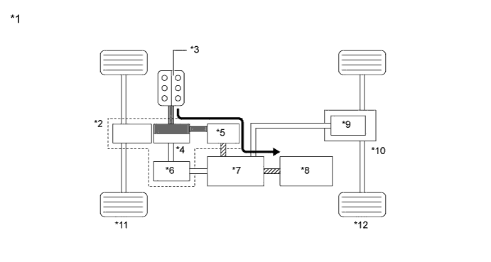
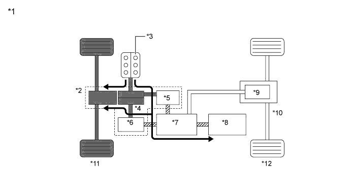
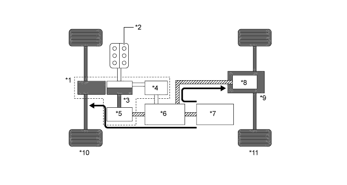
If the SOC of the HV battery is low, it is charged by MG1 which is driven by the engine. This power is also used to power MG2 and MGR.
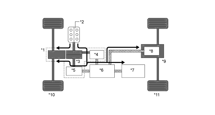
Text in Illustration *1 P313 Hybrid Transaxle (Hybrid Vehicle Transaxle Assembly) *2 Engine (Drive) *3 Compound Gear Unit *4 MG1 (Driven - Generates Electricity) *5 MG2 (Drive) *6 Inverter *7 HV Battery *8 MGR (Drive) *9 Q211 Rear Drive Unit (Rear Traction Motor with Transaxle Assembly) *10 Front Wheels *11 Rear Wheels Electrical Path Mechanical Power Path Power Transmission 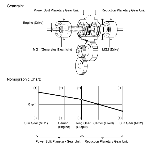
-
-
Constant-speed Cruising
-
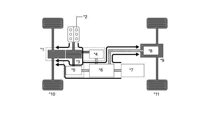
When the vehicle is running under low load and constant-speed cruising conditions, the engine will be operated in its most efficient range to power the vehicle.
-
The motive force from the engine is split into two in the power split planetary gear unit. One portion of the motive force is used to drive the wheels directly and the other is used to generate electricity using MG1.
-
The electricity from MG1 is used to drive MG2. This supports the directly transmitted engine motive force, contributing to fuel efficiency.
-
MGR is not used to output motive force in the constant speed cruising mode, in order to make fuel economy a priority.
Text in Illustration *1 SOC of the HV battery is sufficient: *2 P313 Hybrid Transaxle (Hybrid Vehicle Transaxle Assembly) *3 Engine (Drive) *4 Compound Gear Unit *5 MG1 (Driven - Generates Electricity) *6 MG2 (Drive) *7 Inverter *8 HV Battery *9 MGR *10 Q211 Rear Drive Unit (Rear Traction Motor with Transaxle Assembly) *11 Front Wheels *12 Rear Wheels Electrical Path Mechanical Power Path Power Transmission - - 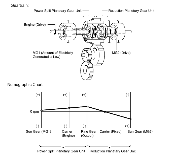
-
If the SOC of the HV battery is low, more engine power is provided to increase the generation of electricity via MG1. This charges the HV battery.
Text in Illustration *1 SOC of the HV battery is low: *2 P313 Hybrid Transaxle (Hybrid Vehicle Transaxle Assembly) *3 Engine (Drive) *4 Compound Gear Unit *5 MG1 (Driven - Generates Electricity) *6 MG2 (Drive) *7 Inverter *8 HV Battery (Charged by MG1) *9 MGR *10 Q211 Rear Drive Unit (Rear Traction Motor with Transaxle Assembly) *11 Front Wheels *12 Rear Wheels Electrical Path Mechanical Power Path Power Transmission - - 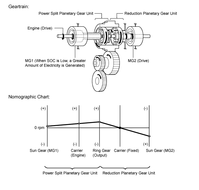
-
-
During Full Throttle Acceleration
-
When the vehicle driving condition changes from low load cruising to full-throttle acceleration, the system supplements the motive force of MG2 with electrical power from the HV battery.
-
MGR operates during full throttle acceleration and drives the rear wheels in order to make acceleration performance a priority.
Text in Illustration *1 P313 Hybrid Transaxle (Hybrid Vehicle Transaxle Assembly) *2 Engine (Drive) *3 Compound Gear Unit *4 MG1 (Driven - Generates Electricity) *5 MG2 (Drive) *6 Inverter *7 HV Battery *8 MGR (Drive) *9 Q211 Rear Drive Unit (Rear Traction Motor with Transaxle Assembly) *10 Front Wheels *11 Rear Wheels Electrical Path Mechanical Power Path Power Transmission -
When more engine power is required, in order to increase the engine speed, the rotation speeds of the related gears change as follows. The sun gear, carrier and ring gear rotate in the (+) direction. The engine rotates the carrier in the (+) direction, and the sun gear applies (-) torque to resist the motive force of the engine. MG1 generates electricity by creating the (-) torque that acts on the sun gear. The electricity created by MG1 is used to drive MG2 and MGR.

-
-
During Deceleration
-
While the vehicle is being driven with the shift lever in the D position and it decelerates, the engine turns off and the engine motive force output to the wheels will be zero. At this time, the wheels drive MG2 and MGR, causing MG2 and MGR to operate as generators and charge the HV battery. While MG2 and MGR are operating as generators, they create a resistance to rotation at the wheels, producing a braking effect.
-
If the vehicle decelerates at a higher speed, the engine (crankshaft) will not stop turning. The engine will maintain a predetermined speed in order to protect the planetary gear unit. This operation is not shown in the following diagrams.

Text in Illustration *1 P313 Hybrid Transaxle (Hybrid Vehicle Transaxle Assembly) *2 Engine (Stopped) *3 Compound Gear Unit *4 MG1 (Rotates Freely) *5 MG2 (Driven - Generates Electricity) *6 Inverter *7 HV Battery *8 MGR (Driven - Generates Electricity) *9 Q211 Rear Drive Unit (Rear Traction Motor with Transaxle Assembly) *10 Front Wheels *11 Rear Wheels Electrical Path Mechanical Power Path Power Transmission -
During deceleration, the ring gear is rotated by the front wheels. Under this condition, due to the engine being stopped, the rotational speed of the carrier is 0 rpm. In addition, since MG1 does not generate any torque, no torque acts on the sun gear. However, the sun gear (MG1) rotates freely in the (-) direction to balance the rotation of the ring gear (Output).
-
-
Driving in Reverse
-
While the vehicle is being driven in reverse, its power is delivered by MG2. At this time, MG2 is spinning in the opposite (-) direction of forward travel, the engine can remain stopped, and MG1 is spinning in the (+) direction without generating electricity.
-
In addition, when more drive force is needed, power is also provided to MGR.
-
While driving in reverse, when any of the conditions monitored by the power management control ECU (HV CPU) such as SOC, battery temperature, engine coolant temperature and electrical load condition reach a specified level, MG1 will be used to start the engine. The following illustration represents an example when the engine is not running.
Text in Illustration *1 P313 Hybrid Transaxle (Hybrid Vehicle Transaxle Assembly) *2 Engine (Stopped) *3 Compound Gear Unit *4 MG1 (Rotates Freely) *5 MG2 (Drive) *6 Inverter *7 HV Battery *8 MGR (Drive) *9 Q211 Rear Drive Unit (Rear Traction Motor with Transaxle Assembly) *10 Front Wheels *11 Rear Wheels Electrical Path Mechanical Power Path Power Transmission -
The conditions of the planetary gear are opposite to those described in "Starting Off". Due to the engine being stopped, the rotational speed of the carrier is 0 rpm but the sun gear (MG1) rotates freely in the (+) direction to balance the rotation of the ring gear (Output).
-
-
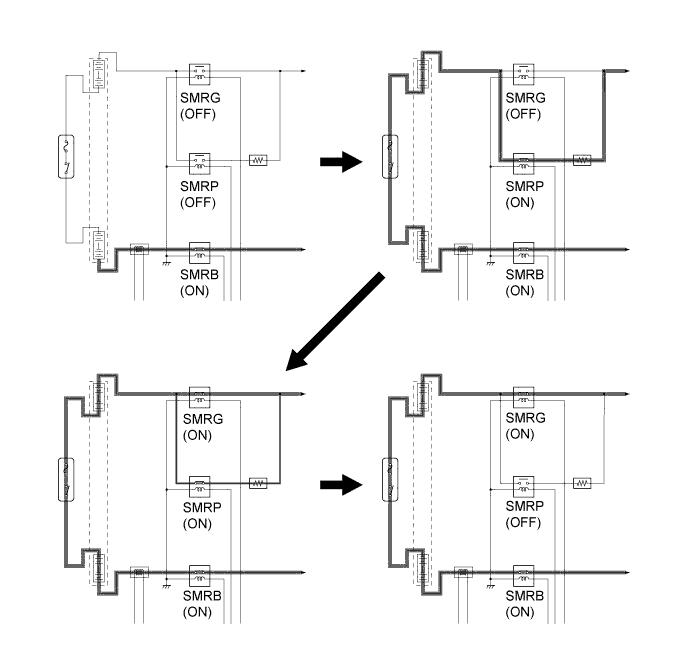
System Main Relay Control
-
The System Main Relays (SMRs) are relays that connect and disconnect the power source of the high-voltage circuit upon receiving a command from the power management control ECU (HV CPU). A total of 3 relays, 1 for the positive side (SMRB), and 2 for the negative side (SMRP, SMRG), are provided to ensure proper operation.
-
The power management control ECU (HV CPU) turns the SMRB on. After that, it turns the SMRP on. After the power management control ECU (HV CPU) has turned the SMRG on, it turns the SMRP off. As the controlled current is initially allowed to pass though a resistor in this manner, the contact point in the circuit is protected from damage that could be cause by a rush current.
-
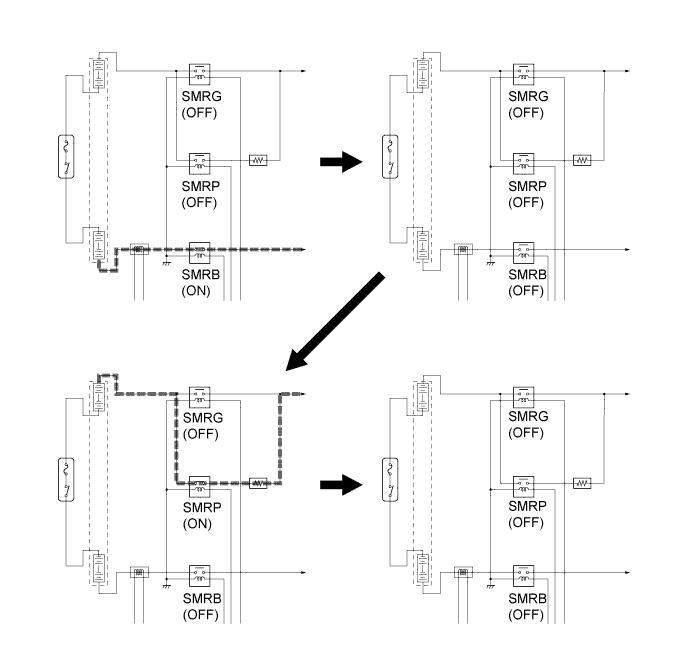
First, the power management control ECU (HV CPU) turns the SMRG off. After is has determined whether the contact points of the SMRG are stuck, it turns the SMRB off. Subsequently, the power management control ECU (HV CPU) turns the SMRP on in order to determine whether the contact points of the SMRB are stuck. Then, it turns the SMRP off.
-
If the power management control ECU (HV CPU) detects that the contact points are stuck, it illuminates the master warning light and indicates "CHECK HYBRID SYSTEM" on the multi-information display, and stores a Diagnostic Trouble Code (DTC) in memory.
-
-
-
DIAGNOSIS
-
In the LEXUS Hybrid Drive, if the power management control ECU (HV CPU) or Motor Generator ECU (MG ECU) detects a malfunction, the power management control ECU (HV CPU) records the fault and memorizes the information that relates to the fault. To inform the driver of the malfunction, the power management control ECU (HV CPU) illuminates or blinks the Malfunction Indicator Lamp (MIL), master warning light and displays a message in the multi-information display.
-
The power management control ECU (HV CPU) will store the respective DTCs of the malfunctions.
-
3-digit information codes (INF codes) have been provided with the conventional DTC as subset of the primary 5-digit code. This enables the troubleshooting procedure to further narrow down a trouble area to identify a problem.
-
INF codes can be accessed by viewing the freeze frame data associated with a hybrid system DTC.
-
The DTCs can be accessed by using the intelligent tester.
-
For details, refer to the Repair Manual.
-