| *A |
F SPORT |
- |
- |
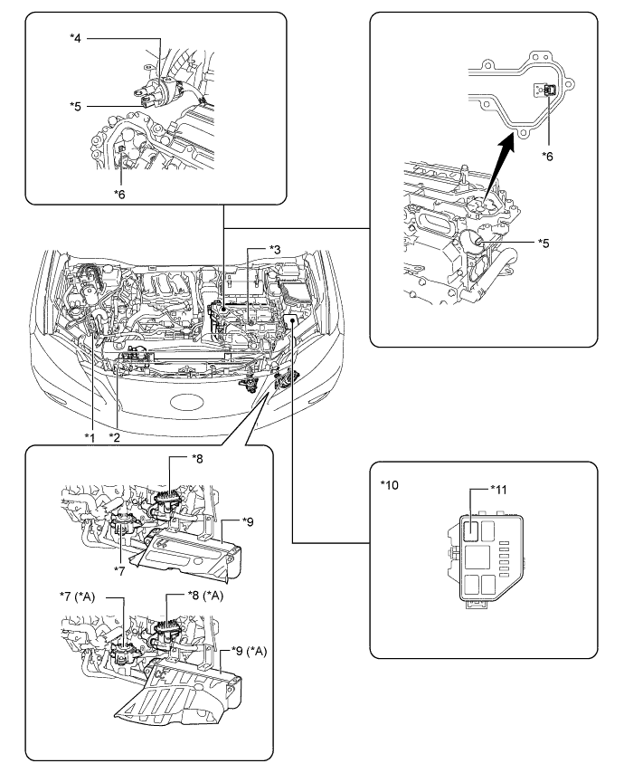
| *1 |
ECM |
*2 |
Cooler Compressor with Motor Assembly |
| *3 |
Inverter with Converter Assembly |
*4 |
Power Cable |
| *5 |
Interlock Switch (For Power Cable) |
*6 |
Interlock Switch (For Inverter Terminal Cover) |
| *7 |
Inverter Water Pump (Water Pump with Motor Assembly) |
*8 |
Oil Pump with Motor Assembly |
| *9 |
Oil Cooler Assembly |
*10 |
Engine Room Relay Block No. 3 |
| *11 |
OIL PMP Relay |
*12 |
Service Plug Grip |
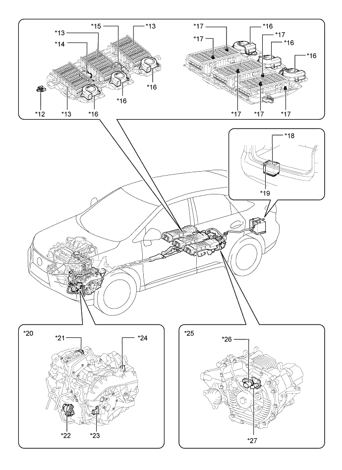
| *13 |
HV Battery Module Group |
*14 |
Battery Voltage Sensor |
| *15 |
Hybrid Junction Block Assembly |
*16 |
Battery Cooling Blower Assembly |
| *17 |
Battery Temperature Sensor |
*18 |
Auxiliary Battery |
| *19 |
Auxiliary Battery Temperature Sensor (Thermistor Assembly) |
*20 |
P313 Hybrid Transaxle (Hybrid Vehicle Transaxle Assembly) |
| *21 |
Resolver (For MG1) and Temperature Sensor (For MG1) |
*22 |
Shift Lever Position Sensor |
| *23 |
Resolver (For MG2) |
*24 |
Temperature Sensor (For MG2) |
| *25 |
Q211 Rear Drive Unit (Rear Traction Motor with Transaxle Assembly) |
*26 |
Resolver (For MGR) |
| *27 |
Temperature Sensor (For MGR) |
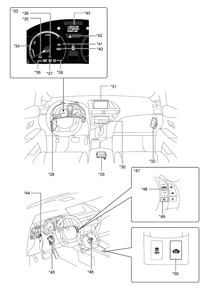
*28 |
Power Management Control ECU (HV CPU) |
| *29 |
Center Airbag Sensor Assembly |
*30 |
Multi-media Module Receiver Assembly |
| *31 |
Multi Display |
*32 |
Skid Control ECU |
| *33 |
Combination Meter Assembly |
*34 |
Hybrid System Indicator |
| *35 |
Malfunction Indicator Lamp (MIL) |
*36 |
Hybrid SNOW Indicator Light |
| *37 |
SPORT MODE Indicator Light |
*38 |
Discharge Warning Light |
| *39 |
ECO MODE Indicator Light |
*40 |
READY Indicator Light |
| *41 |
EV Mode Indicator Light |
*42 |
Master Warning Light |
| *43 |
Multi-information Display |
*44 |
Stop Light Switch |
| *45 |
Accelerator Pedal Position Sensor |
*46 |
Transmission Control Switch |
| *47 |
Multi-information Switch (Steering Pad Switch Assembly) |
*48 |
ENTER Switch |
| *49 |
Menu Switch |
*50 |
EV Drive Mode Switch |