SFI SYSTEM PARTS LOCATION
| *A | Models with Cooled EGR Control | - | - |
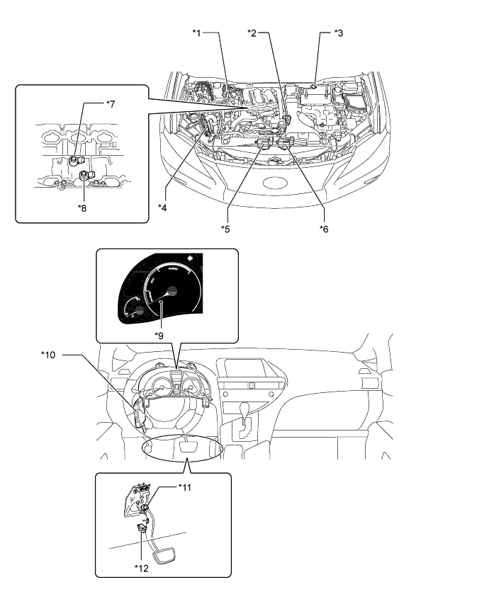
| *1 | Fuel Pump Resister | *2 | Purge VSV |
| *3 | Mass Air Flow Meter | *4 | ECM |
| *5 | Cooling Fan ECU No. 2 | *6 | Cooling Fan ECU No. 1 |
| *7 | Knock Control Sensor (For Bank 1) | *8 | Knock Control Sensor (For Bank 2) |
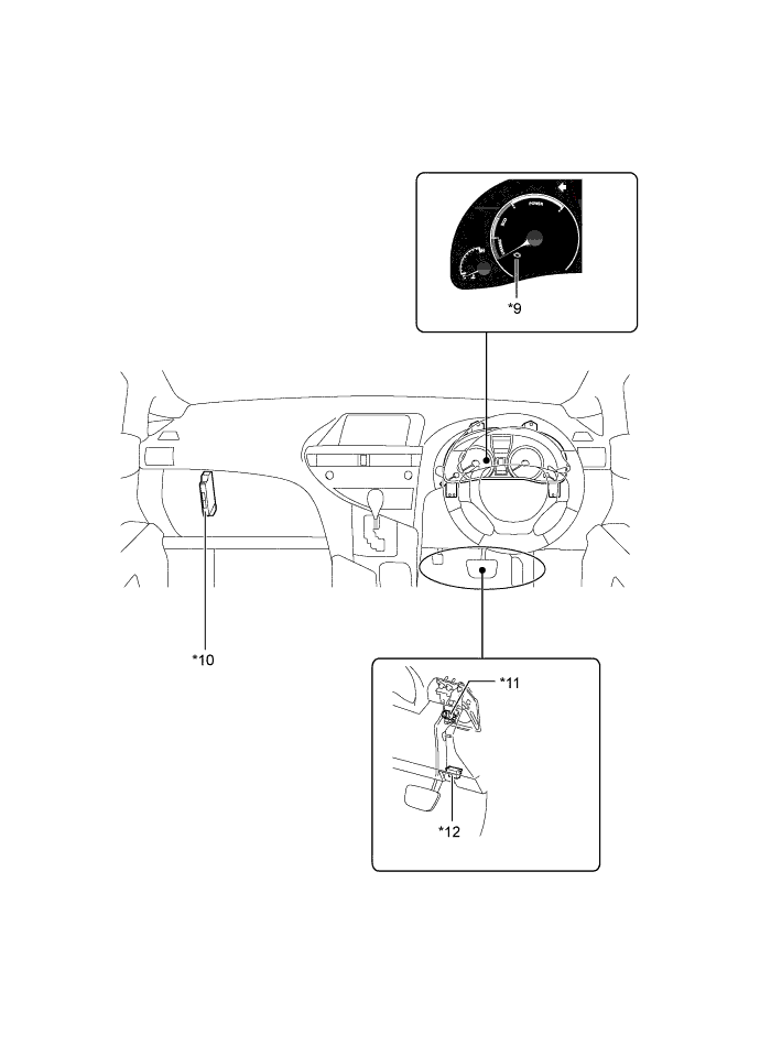
| *9 | Malfunction Indicator Lamp | *10 | Power Management Control ECU |
| *11 | Stop Light Switch | *12 | DLC3 |
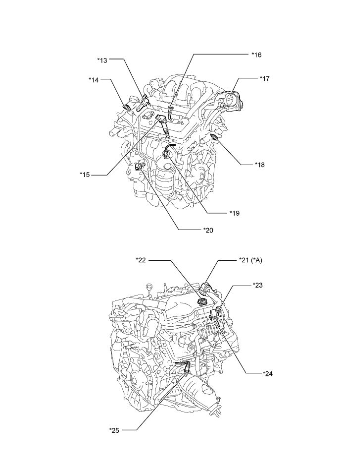
| *13 | Camshaft Timing Oil Control Valve Assembly (Intake, LH) | *14 | Camshaft Position Sensor (Intake, LH) |
| *15 | Ignition Coil Assembly (with Igniter) | *16 | Fuel Injector Assembly |
| *17 | Throttle Body - Throttle Position Sensor - Throttle Control Motor |
*18 | Engine Coolant Temperature Sensor |
| *19 | Air Fuel Ratio Sensor (Bank 2, Sensor 1) | *20 | Crankshaft Position Sensor |
| *21 | EGR Valve | *22 | EFI Vacuum Sensor Assembly |
| *23 | Camshaft Position Sensor (Intake, RH) | *24 | Camshaft Timing Oil Control Valve Assembly (Intake, RH) |
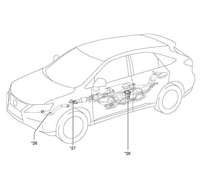
| *25 | Air Fuel Ratio Sensor (Bank 1, Sensor 1) | *26 | Heated Oxygen Sensor (Bank 2, Sensor 2) |
| *27 | Heated Oxygen Sensor (Bank 1, Sensor 2) | *28 | Fuel Pump Assembly |