AIR CONDITIONING SYSTEM DETAILS
-
SYSTEM CONTROL
-
The air conditioning system uses the following controls.
Control Function Customizable*9 Neural Network Control This control is capable of effecting complex control by artificially simulating the information processing method of the nervous system of living organisms in order to establish a complex input/output relationship that is similar to a human brain. Standard (Not Customizable) Automatic Recirculation Control*1 Automatically changes the air inlet mode to fresh air or recirculate mode according to the level of harmful elements in the outside air, cabin temperature, and outside temperature. Standard (Not Customizable) Changes the sensitivity of the smog ventilation sensor. *2 Outlet Air Temperature Control Based on the temperature set at the temperature control switch, the neural network control calculates the outlet air temperature based on the input signals from various sensors. Standard (Not Customizable) The temperature setting for the driver and front passenger is controlled independently in order to provide a separate vehicle interior temperature for the right and left side of the vehicle. Thus, air conditioning control that accommodates occupant preferences has been realized. Standard (Not Customizable) Blower Control Controls the blower motor in accordance with the airflow volume that has been calculated by neural network control based on the input signals from various sensors. Standard (Not Customizable) Automatically increase the blower level when the defroster is on. *3 Air Outlet Control Automatically switches the air outlets in accordance with the outlet mode that has been calculated by neural network control based on the input signals from various sensors. Standard (Not Customizable) In accordance with the engine coolant temperature, outside air temperature, amount of sunlight, required blower, outlet temperature, and vehicle speed conditions, this control automatically switches the blower outlet to FOOT/DEF mode to prevent the windows from becoming fogged when the outside air temperature is low. *3 Air Inlet Control Automatically controls the air inlet control damper to achieve the calculated outlet air temperature that is required. Standard (Not Customizable) Drives the servo motor (for air inlet) according to the operation of the air inlet control switch and moves the dampers to the FRESH or RECIRC position. Standard (Not Customizable) Automatically switches to RECIRCULATE mode to cool the cabin quickly when the air conditioning is turned ON. *4 Cooler Compressor Control Through the calculation of the target evaporator temperature based on various sensor signals, the air conditioning amplifier optimally controls the discharge capacity by regulating the opening extent of the solenoid control valve. Standard (Not Customizable) Turns the air conditioning ON automatically by pressing the AUTO button when the blower is ON and the air conditioning is OFF. *4 Evaporator Control When set to automatic, cooler compressor variable capacity operation is controlled to save power. When set to manual, cooler compressor variable capacity operation is controlled for maximum cooling to dehumidify air and prevent the windows from fogging up. *4 Memory Call Control Memorizes the last air conditioning settings when the engine switch is turned from on(IG) to off in accordance with the ID code of the key that is used to operate the vehicle. The memory call control then recalls the settings if the key is used when the engine switch is turned on (IG). This function operates when both of the following conditions are met:
-
Inside of the outside door handle is touched or the driver door is unlocked using the unlock button, and then the driver door is opened.
-
Engine switch is turned on (IG).
*3 Climate Control Seat Control*5 The air conditioning amplifier drives the blower unit provided in the seatback and seat cushion in accordance with the operation of the climate control seat switch. Standard (Not Customizable) Rear Window Defogger Control
-
Switches the rear defogger and outside rear view mirror heaters on for 15 minutes when the rear defogger button is pressed.
-
Switches them off if the button is pressed while they are operating.
Standard (Not Customizable) Front Wiper Deicer Control*6 Switches the front wiper deicer on for approx. 15 minutes when the front wiper deicer switch is pressed. Standard (Not Customizable) Outside Temperature Indication Control Based on the signals from the ambient temperature sensor, this control calculates the outside temperature. The value is then corrected in the air conditioning amplifier, and shown on the accessory meter assembly*7 or multi display Assembly*8. Standard (Not Customizable) Diagnosis A Diagnostic Trouble Code (DTC) is stored in memory when the air conditioning amplifier detects a problem with the air conditioning system. Standard (Not Customizable)
-
*1: Models with HDD navigation system
-
*2: Default setting is normal.
-
*3: Default setting is on.
-
*4: Default setting is automatic.
-
*5: Models with climate control seat system
-
*6: Models with front wiper deicer system
-
*7: Models without HDD navigation system or Lexus display audio system
-
*8: Models with HDD navigation system or Lexus display audio system
-
*9: The customize setting can be turned on or off. For details, refer to the Repair Manual.
-
-
Neural Network Control
-
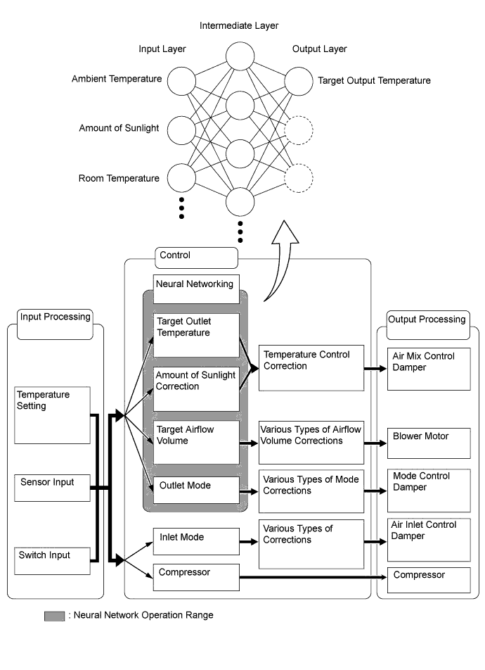
Previously, in automatic air conditioning systems without neural network control, the air conditioning amplifier determined the required outlet air temperature and blower air volume in accordance with the calculation formula that has been obtained based on information received from the sensors. However, because the senses of a person are rather complex, a given temperature is sensed differently, depending on the environment in which the person is situated. For example, a given amount of solar radiation can feel comfortably warm in a cold climate, or extremely uncomfortable in a hot climate. Therefore, as a technique for performing a higher level of control, a neural network has been adopted in the automatic air conditioning system. With this technique, the data that has been collected under varying environmental conditions is stored in the air conditioning amplifier. The air conditioning amplifier can then perform control in a way that provides enhanced air conditioning comfort.
-
The neural network control consists of neurons in the input layer, intermediate layer and output layer. The input layer neurons process the input data of the ambient temperature, the amount of sunlight, and the room temperature based on the outputs of the switches and sensors, and output them to the intermediate layer neurons. Based on this data, the intermediate layer neurons adjust the strength of the links among the neurons. The sum of these is then calculated by the output layer neurons in the form of the required outlet temperature, solar correction, target airflow volume and outlet mode control volume. Accordingly, the air conditioning amplifier controls the servo motors and blower motor in accordance with the control volumes that have been calculated by the neural network control.
-
-
Automatic Recirculation Control (Models with HDD Navigation System)
-
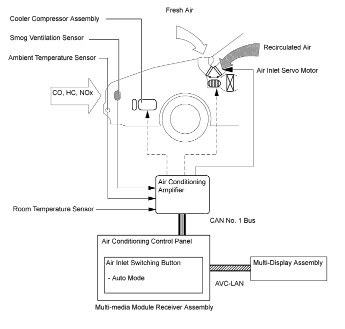
When the automatic recirculation control is operating, the air conditioning amplifier automatically changes air inlet mode to fresh air or recirculate air mode based on signals from the smog ventilation sensor, outside temperature, and room temperature sensors when AUTO air inlet mode is selected.
-
The air conditioning amplifier detects harmful elements (CO, HC and NOx) based on smog ventilation sensor signals and automatically switches air inlet mode to recirculate air mode to prevent such harmful elements from entering the cabin.
-
The air conditioning amplifier detects room temperature based on a room temperature sensor signal and automatically switches air inlet mode to recirculate air mode to prevent the room temperature from becoming too high.
-
The air conditioning amplifier detects outside temperature based on an ambient temperature sensor signal and automatically switches air inlet mode to fresh air mode to prevent the windshield from fogging up.
Tech Tips
The smog ventilation sensor cannot detect elements such as smoke from a bonfire or factory exhaust, foul or animal odors, and dirt or dust particles. Therefore, air inlet mode is not switched in accordance with those elements.
Depending on the direction of the wind, the smog ventilation sensor might not be able to detect the undesirable elements (CO, HC and NOx), allowing them to enter the cabin.
-
-
-
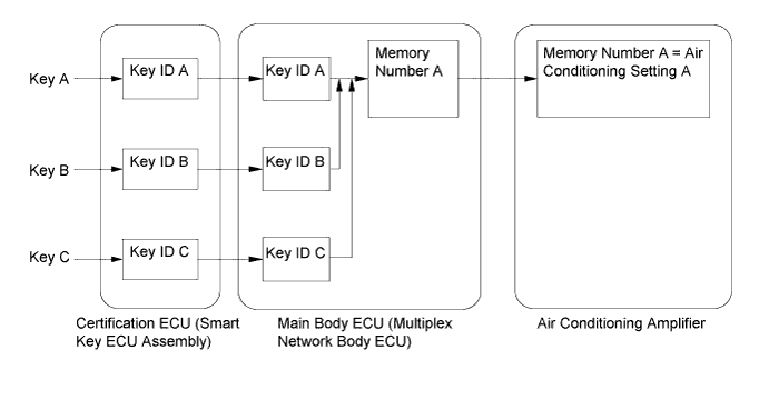
Memory Call Control
-
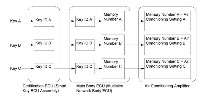
The air conditioning amplifier stores the air conditioning settings for each memory number when the engine switch is turned off.
-
The main body ECU (multiplex network body ECU) converts the key ID code into a memory number, stores it and sends the converted signal to the air conditioning amplifier.
-
The air conditioning amplifier stores the memory number and air conditioning settings.
-
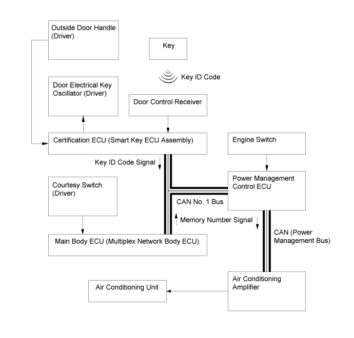
When the doors are unlocked, the certification ECU (smart key ECU assembly) recognizes the key ID code and sends the key ID code to the main body ECU (multiplex network body ECU).
-
Upon receiving the key ID code signal, the main body ECU (multiplex network body ECU) converts the signal into a memory number signal and sends it to the air conditioning amplifier.
-
Then the air conditioning amplifier recalls the stored air conditioning settings based on the memory number signal when the engine switch is turned on (IG).
-
The following air conditioning system settings can be memorized:
Setting Condition Air Conditioning Switch On or Off AUTO Switch On or Off Temperature Setting Driver LO, 16 to 32°C (65 to 85°F) or HI Front Passenger LO, 16 to 32°C (65 to 85°F) or HI Blower Fan Speed Level 1 to 7 Air Inlet Mode Fresh or Recirculate Air Outlet Mode Face, Bi-Level, Foot, Foot and Defroster or Defroster Dual Switch On or Off Tech Tips
-
Memory call control of the air conditioning system can be cancelled or re-enabled using the intelligent tester.
-
The main body ECU (multiplex network body ECU) can store a maximum of 3 memory numbers.
-
The memory call function recalls the key ID that was recognized when the door was unlocked. This happens even if the user brings 2 keys or more, or when the user uses different keys to unlock the door and to turn the engine switch on (IG).
-
Using the intelligent tester, the main body ECU (multiplex network body ECU) can be made to convert the ID numbers of different keys to a desired memory number. Therefore, all key IDs can be converted to an identical memory number, or 2 memory numbers can be divided among 3 keys.
-
For details about key ID code registration, refer to the Repair Manual.
-
-
-
-
CONSTRUCTION
-
Air Conditioning Control Panel
-
A push-button type air conditioning control panel integrated with a radio receiver assembly*1 or multi-media module receiver assembly*2 is adopted.
-
*1: Models with 9-speaker sound system or Lexus display audio system
-
*2: Models with HDD navigation system
-
-
Temperature control switches for the driver and front passenger are provided on the air conditioning control panel to enhance their ease of use.
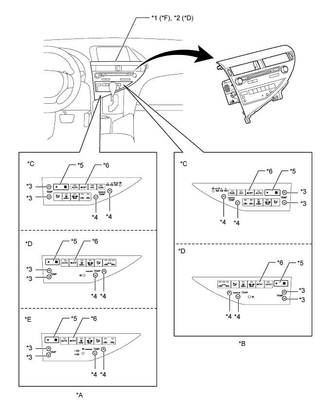
Text in Illustration *A LHD Models *B RHD Models *C Models with 9-speaker Sound System *D Models with HDD Navigation System *E Models with Lexus Display Audio System *F Models with 9-speaker Sound System or Lexus Display Audio System *1 Radio Receiver Assembly *2 Multi-media Module Receiver Assembly *3 Temperature Control Switch (Driver Side) *4 Temperature Control Switch (Front Passenger Side) *5 Blower Fan Speed Switch *6 Blower Fan Off Switch -
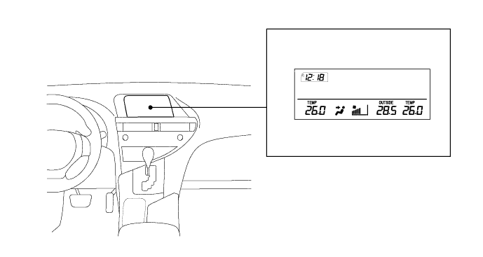
On models with 9-speaker sound system, the air conditioning status is displayed on the accessory meter assembly.
-
On models with the Lexus display audio system, the air conditioning status is displayed on the multi-display assembly. In addition to the air conditioning control panel, a Remote Operation Board is adopted, ensuring remotely operated control for excellent drivability and display visibility.
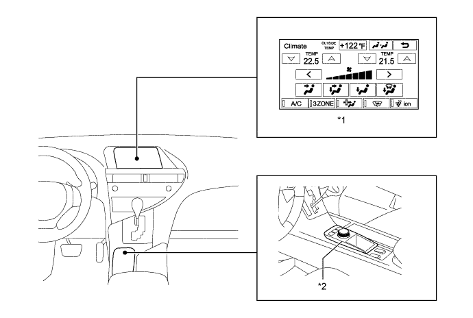
Text in Illustration (Models with Lexus Display Audio System:) *1 Multi-display Assembly *2 Remote Operation Board -
On models with the HDD navigation system, the air conditioning status is displayed on the multi-display assembly. In addition to the air conditioning control panel, a remote touch is adopted, ensuring remotely operated control for excellent drivability and display visibility.
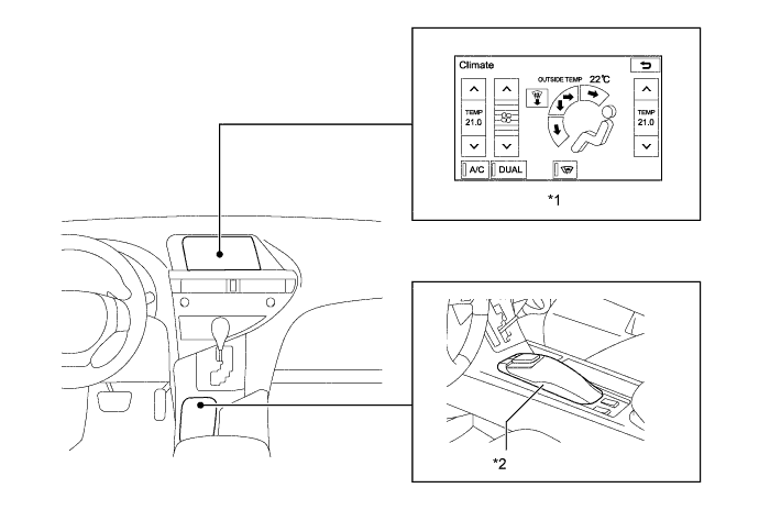
Text in Illustration (Models with HDD Navigation System:) *1 Multi-display Assembly *2 Remote Touch
-
-
Air Conditioning Unit
-
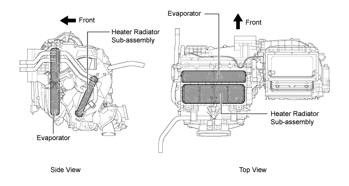
The air conditioning unit consists of the evaporator, heater radiator unit sub-assembly, servo motors, evaporator temperature sensor (cooler thermistor) and blower with fan motor sub-assembly.
-
The evaporator and heater radiator unit sub-assembly are mounted transversely to achieve a compact and lightweight form.
-
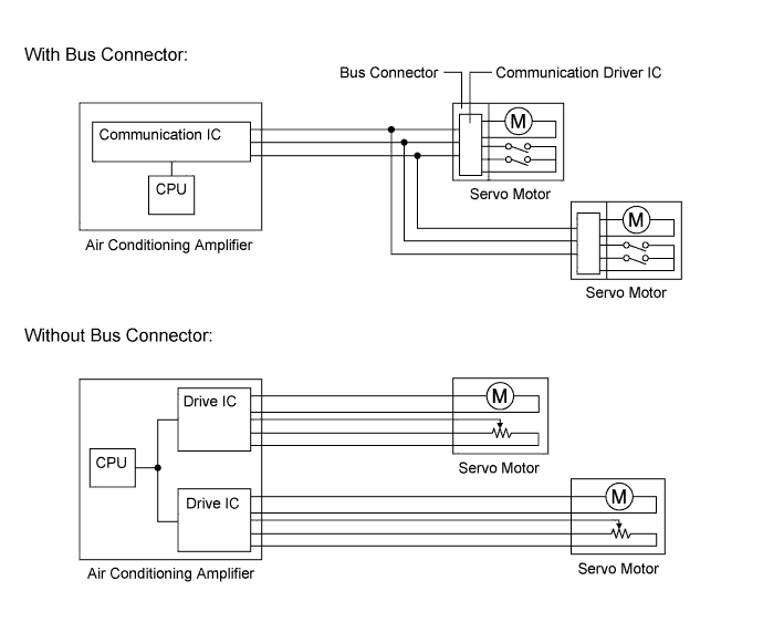
A bus connector is used for the wire harness connection that connects each servo motor to the air conditioning amplifier assembly.
-
-
Evaporator
-
Placing the tanks at the top and the bottom of the evaporator and adopting a micropore tube construction has provided the following benefits:
-
Improved heat exchange efficiency
-
More uniform temperature distribution
-
A thinner evaporator
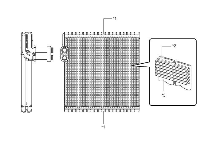
Text in Illustration *1 Tank *2 Cooling Fin *3 Micropore Tube - -
-
-
-
Evaporator Temperature Sensor (Cooler Thermistor)
-
The evaporator temperature sensor (cooler thermistor) detects the temperature of the cooled air immediately past the evaporator in the form of resistance changes, and outputs this data to the air conditioning amplifier.
-
-
Heater Radiator Unit Sub-assembly
-
The compact, lightweight and highly efficient Straight Flow Aluminum (SFA)-II type heater radiator unit sub-assembly is used for the air conditioning system.
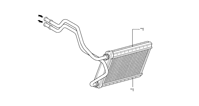
Text in Illustration *1 Tank - -
-
-
Blower with Fan Motor Sub-assembly
-
The blower with fan motor sub-assembly has a built-in blower controller which is controlled by the air conditioning amplifier.
-
-
Bus Connector
-
The Bus connector has a built-in driver IC with a position detection function that communicates with each servo motor connector and actuates the servo motor. This enables bus communication for the servo motor wire harness with a more lightweight construction and a reduced number of wires.
-
-
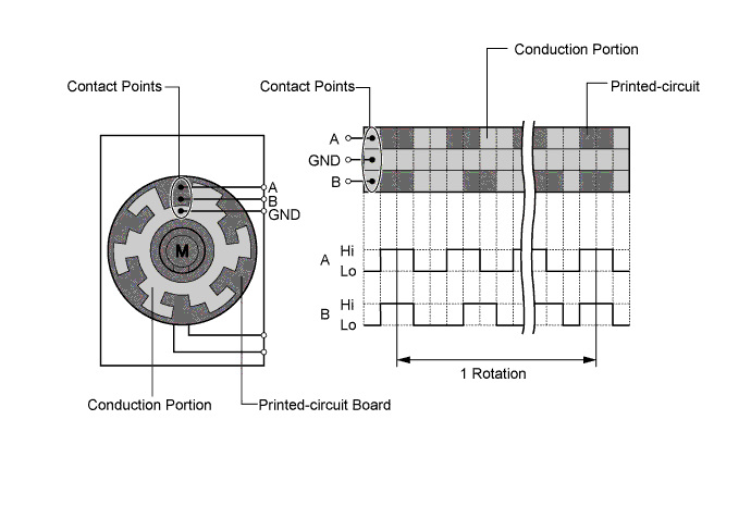
Servo Motor
-
The pulse pattern type servo motor consists of a printed-circuit board and a servo motor. The printed-circuit board has 3 contact points, and can transmit 2 on-off signals to the air conditioning amplifier based on the difference in the pulse phases. The bus connector can detect damper position and direction of movement with this signal.
-
-
Clean Air Filter
-
A pollen-removal type clean air filter is used. This filter is made of polyester and excels in the removal of dust and pollen. Because the filter is made of polyester it can be disposed of easily as a non-hazardous combustible material, a feature provided out of consideration for the environment.
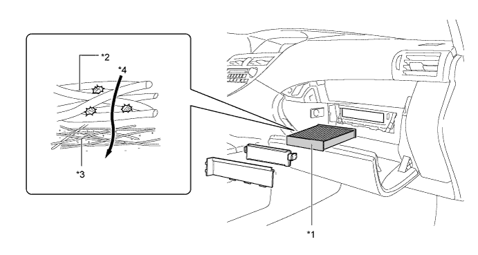
Text in Illustration *1 Clean Air Filter *2 Large Foreign Object Filter Layer *3 Electret Layer *4 Air Flow
-
-
Sub-Cool Accelerator Type Tube
-
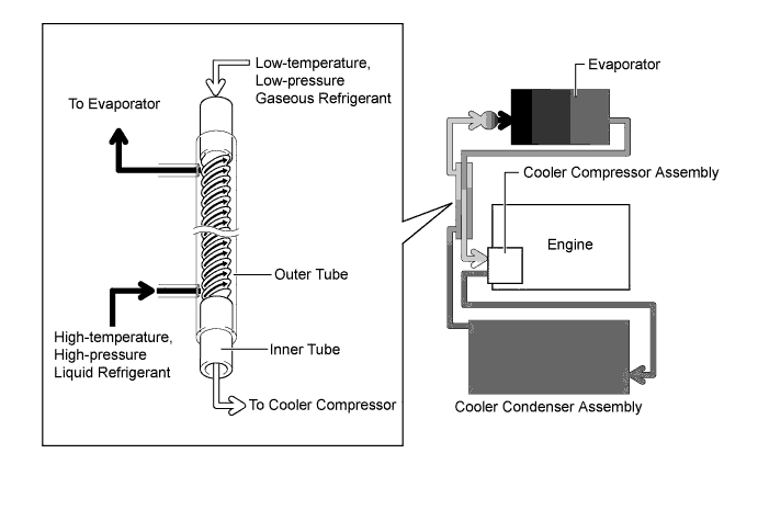
A sub-cool accelerator type air conditioning tube is used to enhance air conditioning cooling performance. It functions as a heat exchanger by making use of the temperature difference between the gaseous refrigerant and liquid refrigerant.
-
The sub-cool accelerator type tube has a double-pipe construction. Helical grooves are embossed into the outer wall of the inner tube. Low-temperature and low-pressure gaseous refrigerant passes through the inner tube. High-temperature and high-pressure liquid refrigerant circulates between the inner tube and outer tube in the gap created by the grooves. Because of the temperature difference, heat exchange occurs.
-
The high-temperature and high-pressure liquid refrigerant circulate along the helical grooves causing the refrigerant to remain in contact with the outer wall of the inner tube for a longer period of time. This realizes an ample exchange of heat.
-
By lowering the temperature of the refrigerant that has passed through the cooler condenser, more liquid refrigerant is supplied to the evaporator and the evaporator is also kept cooler. This enables an enhanced air conditioning cooling effect.
-
-
Cooler Condenser Assembly
-
The cooler condenser assembly consists of 2 cooling portions: a condensing portion and a super-cooling portion. These portions are integrated with a gas-liquid separator (modulator). This cooler condenser assembly uses a sub-cool cycle that offers excellent heat-exchange performance.
-
In the sub-cool cycle, after the refrigerant passes through the condensing portion of the condenser, both the liquid refrigerant and the gaseous refrigerant that could not be liquefied are cooled again in the super-cooling portion. Thus, the refrigerant is sent to the evaporator in an almost completely liquefied state.
-
The desiccant and filter at the bottom of the modulator remove moisture and debris from the refrigerant.
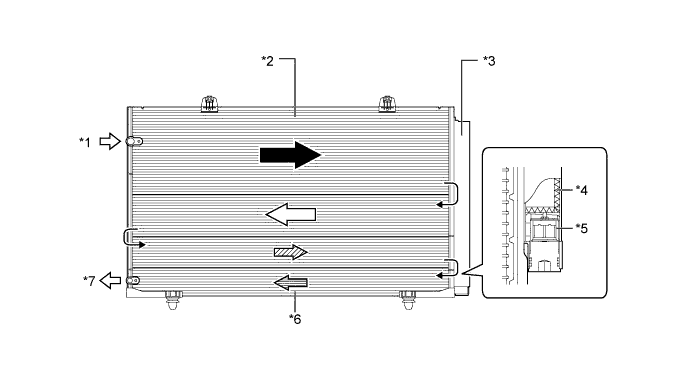
Text in Illustration *1 Gaseous Refrigerant *2 Condensing Portion *3 Modulator *4 Desiccant *5 Filter *6 Super-cooling Portion *7 Liquid Refrigerant - - Tech Tips
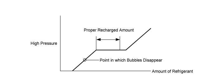
The point at which the air bubbles disappear in the refrigerant of the sub-cool cycle is lower than the proper amount of refrigerant with which the system must be filled. Therefore, if the system is recharged with refrigerant based on the point at which the air bubbles disappear, the amount of refrigerant would be insufficient. As a result, the cooling performance of the system would be affected. Overcharging the system with refrigerant will also lead to reduced performance. For the proper method of verifying the amount of refrigerant and for instructions on how to recharge the system with refrigerant, refer to the Repair Manual.
-
-
Cooler Compressor Assembly
-
The cooler compressor assembly is a continuously variable capacity type air conditioning compressor. Its capacity can be varied in accordance with the cooling load of the air conditioning system.
-
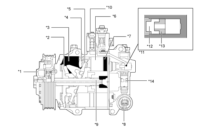
The cooler compressor assembly consists of a pulley, shaft, lug plate, swash plate, piston, shoe, crank chamber, cylinder, air conditioning lock sensor (models with 2GR-FE engine), solenoid control valve with built-in Crank chamber to Suction passage (CS) valve, air conditioning mass flow sensor, oil separator and variable suction side throttle.
-
A plastic Damper Limiter (DL) type pulley is used on models with the 1AR-FE engine and a pulley with a magnetic clutch is used on models with the 2GR-FE engine.
-
The oil separator consists of an oil separator chamber and an oil separator cylinder.
Text in Illustration (Models with 1AR-FE Engine:) *1 Pulley
- Plastic Damper Limiter
*2 Lug Plate *3 Crank Chamber *4 Shoe *5 Swash Plate *6 Piston *7 Cylinder *8 Solenoid Control Valve with Built-in CS Valve *9 Shaft *10 Air Conditioning Mass Flow Sensor *11 Oil Separator *12 Oil Separator Chamber *13 Oil Separator Cylinder *14 Variable Suction Side Throttle 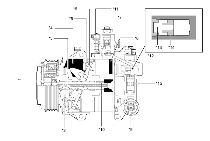
Text in Illustration (Models with 2GR-FE Engine:) *1 Pulley
- Magnetic Clutch
*2 Air Conditioning Lock Sensor *3 Lug Plate *4 Crank Chamber *5 Shoe *6 Swash Plate *7 Piston *8 Cylinder *9 Solenoid Control Valve with Built-in CS Valve *10 Shaft *11 Air Conditioning Mass Flow Sensor *12 Oil Separator *13 Oil Separator Chamber *14 Oil Separator Cylinder *15 Variable Suction Side Throttle - -
-
-
Room Temperature Sensor
-
The room temperature sensor detects the room temperature based on changes in the resistance of its built-in thermistor. This signal is used by the air conditioning amplifier.
-
-
Ambient Temperature Sensor
-
The ambient temperature sensor detects the ambient temperature based on changes in the resistance of its built-in thermistor. This signal is used by the air conditioning amplifier.
-
-
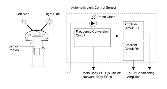
Automatic Light Control Sensor
-
The automatic light control sensor consists of a photo diode, 2 amplifier circuits and a frequency converter circuit.
-
The automatic light control sensor detects (in the form of changes in the current that flows through the built-in photo diode) the changes in the amount of sunlight from its left and right sides (2 directions) and outputs these sunlight strength signals to the air conditioning amplifier for the automatic air conditioning control.
-
-
-
OPERATION
-
Mode Position and Door Operation
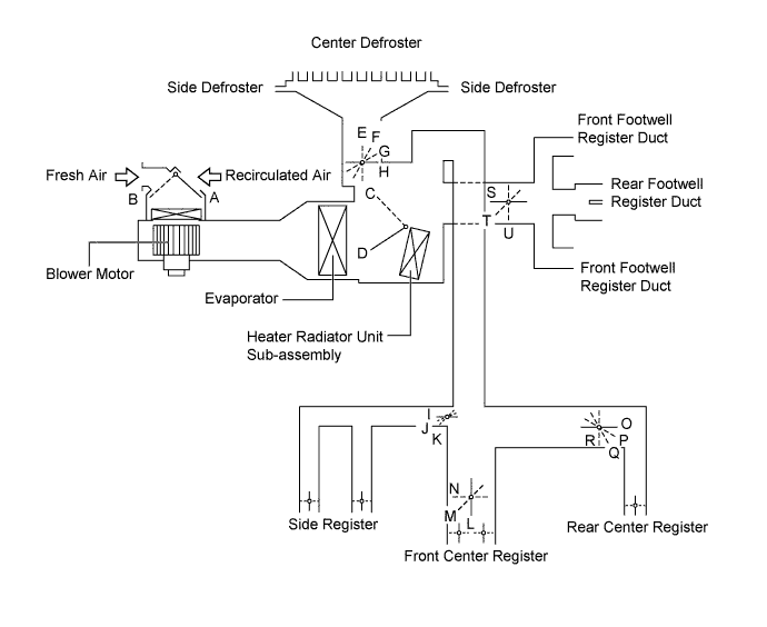
Control Door Operation Position Door Position Operation Air Inlet Control Door FRESH A Brings in fresh air. RECIRCULATION B Recirculates internal air. Air Mix Control Door MAX COLD to MAX HOT
Temperature Setting
C - D Varies the mixture ratio of warm air and cool air in order to regulate the temperature continuously between hot and cold. Mode Control Door 
FACE H, I, L, O, U Air blows out of the front center register, rear center register and side register ducts. 
BI-LEVEL H, J, M, P, T Air blows out of the front and rear center register, side register and front and rear footwell register ducts. 
FOOT G, K, N, Q, S Air blows out of the footwell register and side register ducts. In addition, air blows out slightly from the center defroster and side defroster. 
FOOT AND DEFROSTER F, K, N, Q, S Defrosts the windshield through the center defroster, side defroster, quarter defroster, side register and rear center register ducts, while air is also blown out from the front and rear footwell register ducts. 
DEFROSTER E, K, N, R, U Defrosts the windshield through the center defroster, side defroster, quarter defroster and side register ducts. -
Air Outlets and Airflow Volume
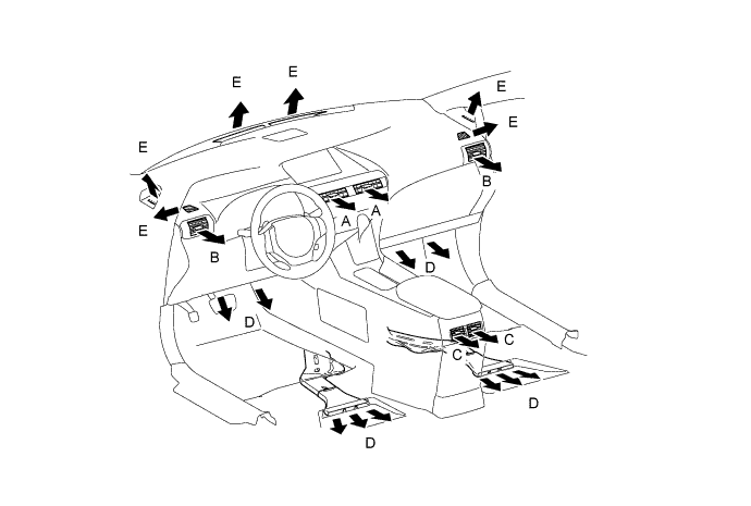
Indication Mode Center Side Rear Footwell Defroster A B C D E FACE 
- - BI-LEVEL 
- FOOT - FOOT AND DEFROSTER - DEFROSTER - - - The size of the circle ○ indicates the proportion of airflow volume.
-
Cooler Compressor Operation
-
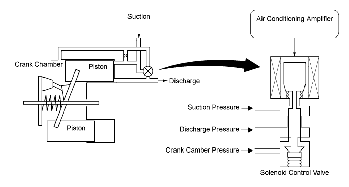
Variable Capacity Operation
-
A solenoid control valve is connected to the suction passage, the discharge passage and the crank chamber passage.
-
The solenoid control valve operates under duty cycle control in accordance with the signals from the air conditioning amplifier.
-
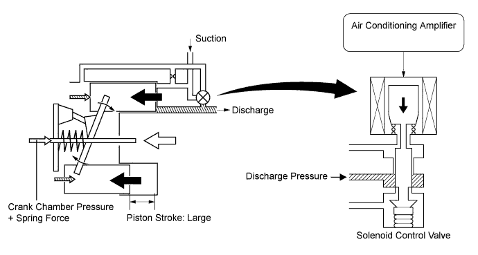
When the solenoid control valve closes (solenoid coil is energized), a difference in pressure is created and the pressure in the crank chamber decreases. Then, the pressure that is applied to the right side of the piston becomes greater than the pressure that is applied to the left side of the piston. This compresses the spring and tilts the lug plate. As a result, the piston stroke increases and the discharge capacity increases.
-
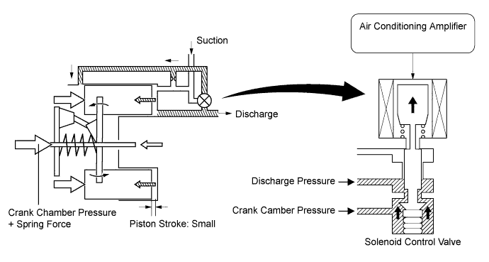
When the solenoid control valve opens (solenoid coil is not energized), the difference in pressure disappears. Then, the pressure that is applied to the left side of the piston becomes the same as the pressure that is applied to the right side of the piston. Thus, the spring elongates and eliminates the tilt of the lug plate. As a result, the piston stroke is small, decreasing the discharge capacity is reduced.
-
-
Air Conditioning Lock Sensor Operation (Models with 2GR-FE Engine)
-
The air conditioning lock sensor outputs a pulley rotation signal to the air conditioning amplifier.
-
The air conditioning amplifier compares this signal with the engine speed signal sent from the ECM to judge if the cooler compressor assembly is locked. If the cooler compressor assembly is locked, the magnetic clutch is turned off.
-
-
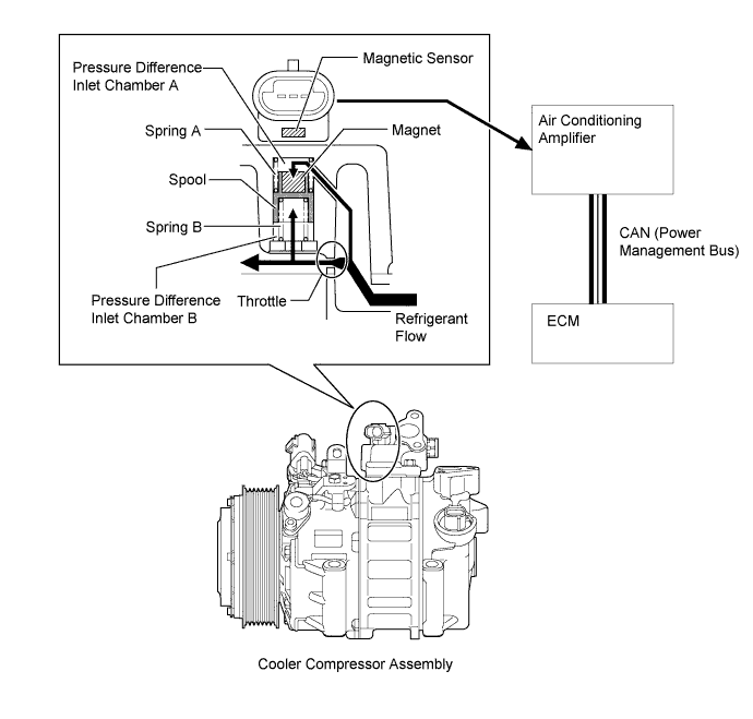
Air Conditioning Mass Flow Sensor Operation
-
Using a spool that changes its position according to the amount of refrigerant flow, the air conditioning mass flow sensor detects the amount of refrigerant flow.
-
The air conditioning mass flow sensor outputs a voltage by converting the change of magnetic flux that occurs due to the magnet that is installed on the spool.
-
The spool changes its position according to the pressure difference between the pressure before and after the refrigerant flow throttle.
-
If the amount of refrigerant flow is small, the difference in pressure between pressure difference inlet chamber A and pressure difference inlet chamber B is low, allowing the force of spring B to push up the spool.
-
If the amount of refrigerant flow is large, the pressure difference between pressure difference inlet chamber A and B is high. The pressure difference overwhelms the force of spring B, and the spool moves down.
-
Based on the amount of refrigerant flow detected by the air conditioning flow sensor, the air conditioning amplifier and ECM cooperatively control the cooler compressor assembly and the engine.
-
-
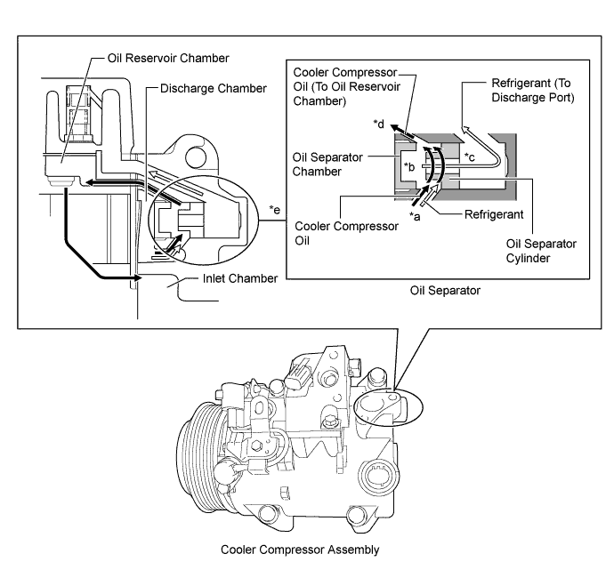
Oil Separator Operation
-
A mixture of refrigerant and cooler compressor oil flows into the oil separator chamber from the discharge chamber (*a).
-
The force of the refrigerant and oil mixture flow turns the oil separator cylinder, allowing the oil and refrigerant to be centrifugally separated (*b).
-
The separated refrigerant flows to the condenser through the discharge port (*c).
-
The separated oil circulates and lubricates the inside of the cooler compressor by flowing through the oil reservoir chamber, inlet chamber, cylinder and discharge chamber. In addition, the amount of oil that is discharged by the cooler compressor is suppressed (*d).
-
The oil separator is installed in the refrigerant passage to separate cooler compressor oil from the refrigerant that is discharged. This helps to prevent the cooler compressor oil from flowing into the air conditioning system and reducing cooling effectiveness (*e).
-
-
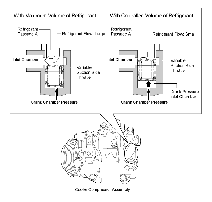
Variable Suction Side Throttle Operation
-
Refrigerant inlet pressure is applied to the top of the variable suction side throttle and crank chamber pressure to the bottom of the variable suction side throttle.
-
The pressure difference moves the variable suction side throttle up and down, expanding and contracting the refrigerant inlet passage.
-
When the refrigerant flow is at its maximum, the refrigerant inlet pressure is greater than the crank chamber pressure. This causes the variable suction side throttle to move down, fully opening the refrigerant inlet passage and lowering the refrigerant inlet resistance.
-
When the amount of refrigerant flow is controlled, the crank chamber pressure is greater than the refrigerant inlet pressure, raising the variable inlet throttle to contract the flow passage.
-
These controls suppress noise by reducing pulsation from the refrigerant inlet.
-
-
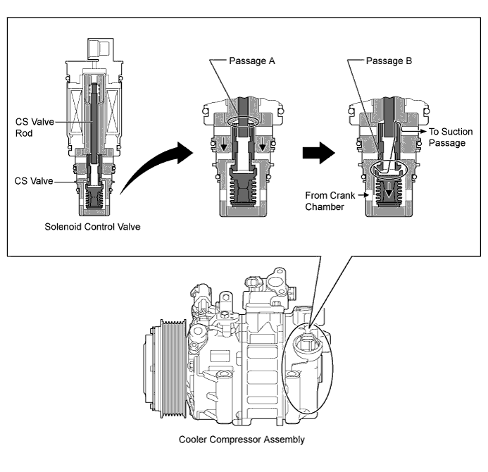
CS Valve Operation
-
The Crank chamber to Suction passage (CS) valve, built into the solenoid control valve, operates in accordance with the suction pressure. The CS valve consists of passage A and passage B.
-
If the vehicle is left parked for a long period, refrigerant may accumulate in the crank chamber due to the heat capacity difference.
-
The solenoid control valve is controlled by the air conditioning amplifier assembly. While the cooler compressor assembly is operating, the solenoid control valve pushes down the CS valve rod and open passage A (*a).
-
Under the above condition, only if the refrigerant accumulates in the crank chamber, the crank chamber pressure will become high. As a result, the bellows will contract because of the pressure difference with its internal pressure (vacuum), and opens passage B (*b).
-
This causes the accumulated refrigerant to be drawn in via passage A and B, clearing the accumulated refrigerant earlier and ensuring a more immediate cooling effect.
-
-
-
-
DIAGNOSIS
-
The air conditioning amplifier has a diagnosis function. It stores a record of any air conditioning system failures in its memory in the form of Diagnostic Trouble Codes (DTCs).
-
There are 2 methods for reading DTCs. One is to use the intelligent tester, and the other is to read the DTCs using the accessory meter assembly*1 or multi-display assembly*2. For details, refer to the Repair Manual.
-
*1: Models with 9-speaker sound system
-
*2: Models with HDD navigation system or Lexus display audio system
-
-