PRE-CRASH SAFETY SYSTEM DETAILS
-
FUNCTION OF MAIN COMPONENTS
Component Function Combination Meter Assembly PCS Warning Light Illuminates or flashes to warn the driver in accordance with signals from the seat belt control ECU or driving support ECU assembly. Multi-information Display Displays a warning message to inform or warn the driver of the system condition in accordance with signals from the seat belt control ECU or driving support ECU assembly. Master Warning Light Illuminates to warn the driver in accordance with signals from the seat belt control ECU or driving support ECU assembly. Buzzer Sounds to warn the driver in accordance with signals from the seat belt control ECU or driving support ECU assembly when the system is malfunctioning. Millimeter Wave Radar Sensor Radiates millimeter wave radar forward, uses the reflected millimeter wave for detecting the presence of a vehicle ahead, the vehicle-to-vehicle distance, and the relative speed, and then transmits this information to the driving support ECU assembly. Front Seat Outer Belt Seat Belt Motor Retracts the seat belt in accordance with signals received from the seat belt control ECU. Front Seat Inner Belt (Driver Seat) Seat Belt Buckle Switch Detects the condition (verifies if the belt is buckled) of the driver seat belt and transmits a signal to the airbag sensor assembly. Front Seat Inner Belt (Front Passenger Seat) Seat Belt Buckle Switch Detects the condition (verifies if the belt is buckled) of the front passenger seat belt and transmits a signal to the seat belt control ECU. Airbag Sensor Assembly Transmits the condition (fastened or unfastened) of the driver seat belt to the seat belt control ECU. Driving Support ECU Assembly
-
Makes judgments on whether the possibility of a collision is high or a collision is unavoidable based on the information received from the millimeter wave radar sensor. It then outputs a seat belt operation signal and brake assist standby request signal if required.
-
Makes judgments on whether the possibility of a collision is high or a collision is unavoidable based on the information received from the millimeter wave radar sensor. It then outputs a seat belt operation signal and brake assist standby or brake activate request signal if required.*
Seat Belt Control ECU Receives the seat belt operation request signal from the driving support ECU assembly or skid control ECU and operates the seat belts. Headup Display Unit (Combination Meter Mirror ECU) Displays a warning message on the windshield to inform or warn the driver of the system condition in accordance with signals from the seat belt control ECU or driving support ECU assembly. Brake Actuator Skid Control ECU
-
Receives a brake assist standby request signal from the driving support ECU assembly and switches the brake assist to standby mode. When a stop light switch signal is input, it activates the brake assist.
-
Even if the driver does not apply the brakes, if the skid control ECU receives a pre-crash brake request signal from the driving support ECU assembly, it applies the brakes while ensuring vehicle stability.*
-
Determines if the brakes have been applied suddenly through signals received from the master cylinder pressure sensor, and outputs a seat belt operation signal to the seat belt control ECU.
-
Determines the presence of understeer or oversteer and outputs a seat belt operation signal to the seat belt control ECU.
-
Transmits vehicle speed signals to the driving support ECU assembly.
Master Cylinder Pressure Sensor Detects the master cylinder pressure and transmits a signal to the skid control ECU. Pump Motor Receives an operation signal from the skid control ECU and generates hydraulic pressure for brake control. Stop Light Switch Detects if the brake pedal is depressed and transmits a signal to the skid control ECU. Speed Sensor Detects speed of each wheel speed and transmits the signals to the skid control ECU. Yawrate Sensor Detects the yaw rate and lateral/longitudinal deceleration of the vehicle and transmits the signals to the skid control ECU and the driving support ECU assembly. Steering Angle Sensor Detects the angle and direction of steering and transmits a signal to the skid control ECU and the driving support ECU assembly. Pre-crash Brake OFF Switch* Disables the pre-crash brake operation when the switch is turned on. The PCS warning light illuminates to notify that the pre-crash brake system is off. Skid Control Buzzer Assembly Sounds to warn the driver in accordance with signals from the skid control ECU.
-
*: Models with pre-crash brake
-
-
OPERATING CONDITION
-
Operating Condition
Operating Condition When a collision with an obstacle in front of the vehicle or a collision with the vehicle ahead is determined to be unavoidable.
The pre-crash seat belt operates even under the following conditions:
-
When the brakes are suddenly applied.
-
When the front wheels lose grip in relation to the rear wheels (understeer tendency).
-
When the rear wheels lose grip in relation to the front wheels (oversteer tendency).
Non-operating Condition
-
The vehicle collides with an object that the millimeter wave radar sensor cannot detect (plastic items, safety cones, etc.) or cannot detect in a stable manner (people, bicycles, motorcycles, trees, animals, snow fence, etc.).
-
The engine switch is off or on (ACC).
-
The multi-information display in the combination meter assembly displays [CHECK PCS SYSTEM] and [PCS TEMPORARILY NOT AVAILABLE] warning messages.
-
The vehicle collides with an object located outside the detection area of the millimeter wave radar sensor.
-
-
The pre-crash safety system consists of the following three operations: a pre-crash safety (unavoidable collision) operation, understeer or oversteer tendency operation and sudden braking operation. The operating conditions of impact dampening components are indicated in the following chart.
Models without Pre-crash Brake Operation Operating Condition Impact Dampening Component Understeer or Oversteer Tendency Operation
-
Engine switch is on (IG).
-
Seat belt is buckled.
-
Vehicle speed is approximately 30 km/h (19 mph) or more.
Pre-crash Seat Belt Control Sudden Braking Operation
-
Engine switch is on (IG).
-
Seat belt is buckled.
-
Vehicle speed is approximately 30 km/h (19 mph) or more.
Pre-crash Safety Operation
-
Engine switch is on (IG).
-
Seat belt is buckled.
-
Vehicle speed is approximately 5 km/h (4 mph) or more.
-
Oncoming vehicle relative speed is approximately 30 km/h (19 mph) or more.
Pre-crash Seat Belt Control
-
Engine switch is on (IG).
-
Brake pedal is depressed.
-
Vehicle Speed is approximately 30 km/h (19 mph) or more.
-
Oncoming vehicle relative speed is approximately 30 km/h (19 mph) or more.
Pre-crash Brake Assist Control Models with Pre-crash Brake Operation Operating Condition Impact Dampening Component Understeer or Oversteer Tendency Operation
-
Engine switch is on (IG).
-
Seat belt is buckled.
-
Vehicle speed is approximately 30 km/h (19 mph) or more.
Pre-crash Seat Belt Control Sudden Braking Operation
-
Engine switch is on (IG).
-
Seat belt is buckled.
-
Vehicle speed is approximately 30 km/h (19 mph) or more.
Pre-crash Safety Operation
-
Engine switch is on (IG).
-
Seat belt is buckled.
-
Vehicle speed is approximately 5 km/h (4 mph) or more.
-
Oncoming vehicle relative speed is approximately 30 km/h (19 mph) or more.
Pre-crash Seat Belt Control
-
Engine switch is on (IG).
-
Pre-crash brake OFF switch is not pressed.
-
Vehicle speed is approximately 15 km/h (10 mph) or more.
-
Oncoming vehicle relative speed is approximately 30 km/h (19 mph) or more.
Pre-crash Brake Control
-
Engine switch is on (IG).
-
Brake pedal is depressed.
-
Vehicle speed is approximately 30 km/h (19 mph) or more.
-
Oncoming vehicle relative speed is approximately 30 km/h (19 mph) or more.
Pre-crash Brake Assist Control -
-
-
SYSTEM CONTROL
-
Understeer or Oversteer Tendency Operation
1) While the vehicle is traveling at approximately 30 km/h (19 mph) or more, the skid control ECU determines if skid recovery will be difficult based on the signals from the steering angle sensor, yawrate sensor and speed sensors. 2) The skid control ECU sends a seat belt operation request signal to the seat belt control ECU. 3) The seat belt control ECU determines the seat belt motor operating conditions based on this signal and the seat belt buckle switch signal. It then retracts the slack in the seat belts by operating the seat belt motors. 4) The seat belts return to a normal state when the relevant conditions of the vehicle have stabilized. 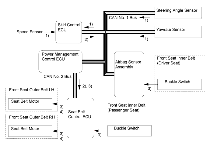
-
Sudden Braking Operation
1) While the vehicle is traveling at approximately 30 km/h (19 mph) or more, the skid control ECU can determine a sudden braking condition based on the signals from the master cylinder pressure sensor, stop light switch and speed sensors. 2) At this time, the skid control ECU outputs a seat belt operation request signal to the seat belt control ECU. 3) The seat belt control ECU determines the seat belt motor operating conditions based on this signal and seat belt buckle switch signals. Then, it retracts the slack in the seat belts by operating the seat belt motors. 4) The seat belts return to a normal state when the brake pedal is released. 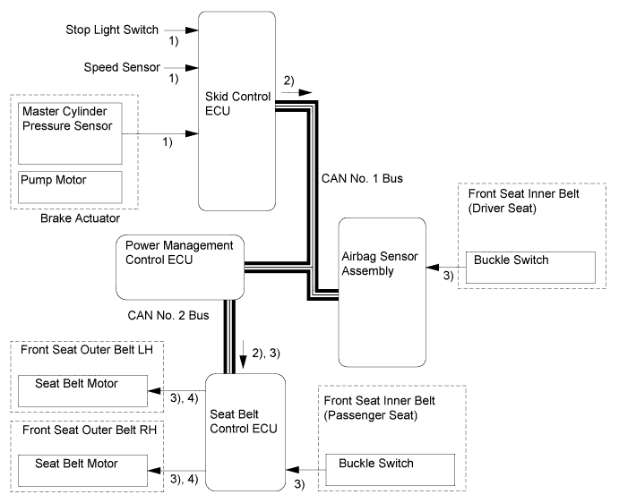
-
Pre-crash Safety Operation
Models without Pre-crash Brake 1) The driving support ECU assembly determines that the possibility of a collision is high based on signals received from the millimeter wave radar sensor, steering angle sensor, speed sensor and yawrate sensor. 2) The driving support ECU assembly sends a brake assist control request signal to the skid control ECU. 3) The driving support ECU assembly determines that a collision is unavoidable based on signals received from the millimeter wave radar sensor, steering angle sensor, speed sensor and yawrate sensor. 4) The driving support ECU assembly sends a seat belt operation request signal to the seat belt control ECU. 5) The seat belt control ECU determines the seat belt motor operation condition based on this signal and the seat belt buckle switch signal, and retracts the slack in the seat belts by operating the seat belt motors. 6) When the brake assist is in the standby condition and the stop light switch ON signal is input into the skid control ECU, this ECU operates the brake assist based on the master cylinder pressure sensor. 7) If no collision occurs, the seat belts and the brake assist will return to their normal states. 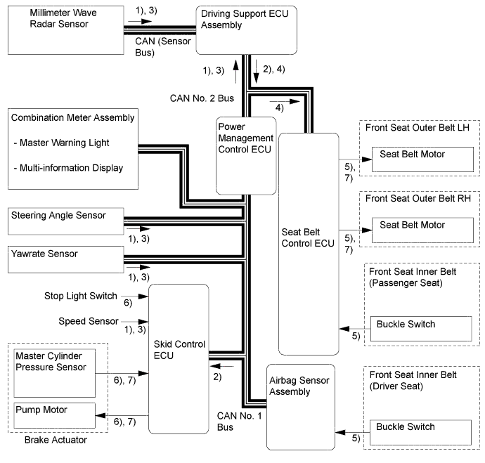
Models with Pre-crash Brake 1) The driving support ECU assembly determines that the possibility of a collision is high based on the signals received from the millimeter wave radar sensor, steering angle sensor, speed sensor and yawrate sensor. 2) The driving support ECU assembly transmits a BRAKE! warning display request signal to the multi-information display and headup display, and a warning buzzer request signal to the skid control ECU. 3) The driving support ECU assembly outputs a pre-crash brake assist request signal to the skid control ECU. Upon receiving this signal, the skid control ECU switches the brake assist to the standby condition. 4) The driving support ECU assembly determines that an unavoidable collision condition exists based on the signals received from the millimeter wave radar sensor, speed sensor, steering angle sensor and yawrate sensor. 5) The driving support ECU assembly outputs a seat belt operation request signal to the seat belt control ECU and a pre-crash brake request signal to the skid control ECU. 6) The seat belt control ECU determines the seat belt motor operation condition based on this signal and the seat belt buckle switch signal, and retracts the slack in the seat belts by operating the seat belt motors. At the same time, the skid control ECU activates the brake actuator as a pre-crash brake control and decelerates the vehicle. 7) If no collision occurs, the seat belts and brake assist will return to their normal states. 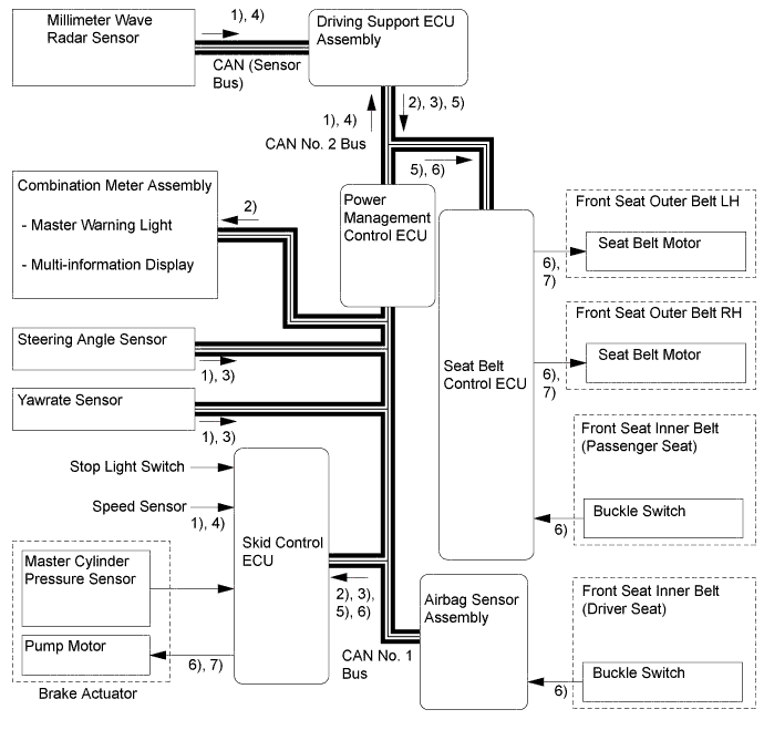
-
-
CONSTRUCTION
-
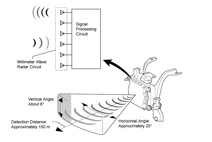
Millimeter Wave Radar Sensor
-
The millimeter wave radar sensor consists of a millimeter wave radar circuit signal processing circuit and CPU.
-
The millimeter wave radar circuit consists of 1 transmission antenna and 5 reception antennas.
-
The millimeter wave radar outputs waves when the vehicle speed is above 0 km/h (0 mph), and not when the vehicle speed is at 0 km/h (0 mph). The millimeter wave radar uses frequencies in the 76 GHz band.
-
The reception antennas receive the millimeter wave radar waves that have been reflected.
-
The signal processing circuit detects the distance, relative speed, and the direction of the object by generating millimeter wave radar waves and calculating the signals received by the reception antennas. Then, it transmits this information to the driving support ECU assembly.
-
The millimeter wave radar sensor is also used by the dynamic radar cruise control system.
-
Calculation Method
-
The distance to the object, azimuth (horizontal angle), and relative speed are calculated from the information that is provided by the refection millimeter wave radar as described below.
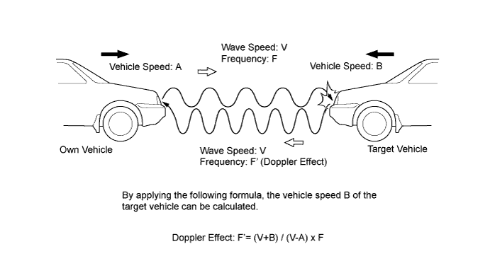
Distance Calculated from the length of time that has elapsed from the time the waves of the millimeter wave radar have been emitted, until the waves reflected by the millimeter wave radar are received. Azimuth Calculated from the angle of the waves reflected by the millimeter wave radar that have been received. Relative Speed Calculated by utilizing the changes (Doppler effect*) that occur in the frequencies of the reflected millimeter wave radar waves. Tech Tips
*: The Doppler effect causes the observer to perceive the radio waves emitted by a moving object to be at higher frequencies as it approaches, and to be at lower frequencies as it recedes. This phenomenon is created because when an object is located far away, the radio waves are perceived at higher frequencies than they are at the radio source.
Tech Tips
-
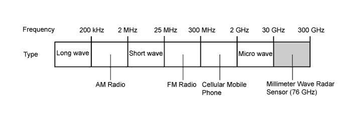
Millimeter wave radar uses an extremely high frequency band between 30 GHz and 300 GHz, with an extremely short wavelength between 1 and 10mm (0.04 to 0.40 in.) in a vacuum. The millimeter wave radar sensor of the pre-crash safety system uses frequencies in the 76 GHz band.
-
The millimeter wave radar is less affected by weather conditions such as rain, fog, or snow, and provides excellent characteristics for recognizing objects. Therefore, it is well suited to the pre-crash safety system and the dynamic radar cruise control system.
-
-
-
-
-
OPERATION
-
Combination Meter
-
The combination meter uses a master warning light, PCS warning light, buzzer, multi-information display and headup display to provide the driver with pre-crash safety system warnings and indications.
-
If the driving support ECU assembly determines that the possibility of a collision is high, it sends a signal to the combination meter. Upon receiving this signal, the combination meter indicates a warning on the multi-information display, headup display, master warning light, PCS warning light and sounds the skid control buzzer assembly. Details are indicated below.
Headup Display Multi-information Display Master Warning Light PCS Warning Light Skid Control Buzzer Assembly 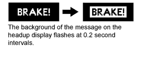

- Flashes Sounds continuously -
2 types of warning messages are used for the pre-crash safety system, as described below. The pre-crash safety system will not operate when these messages appear on the combination meter.
Multi-information Display Detail Master Warning Light PCS Warning Light Buzzer DTC 
This message appears when the seat belt control ECU or driving support ECU assembly detects a system malfunction. Illuminates Flashes Sounds once ○ 
This message appears when the seat belt control ECU or driving support ECU assembly determines the following conditions:
-
Dirty millimeter wave radar sensor
-
Poor weather condition
-
Overheated seat belt control ECU
After these conditions have been resolved, the system will operate normally.
- Illuminates - X
-
○: Repair is required/DTC are stored
-
X: Repair is not required/DTC are not stored
-
-
-
-
DIAGNOSIS
-
Initial Check
-
The seat belt control ECU performs an initial check on the system for approximately 3 seconds after the engine switch has been turned on (IG).
-
-
Monitor Function
-
After completing the initial check, the pre-crash safety system becomes ready to operate. During this time, the seat belt control ECU and driving support ECU assembly periodically monitors the system for any malfunctions.
-
-
Diagnostic Trouble Code (DTC)
-
If the seat belt control ECU or driving support ECU assembly detects a malfunction in the pre-crash safety system, it stores a 5-digit Diagnostic Trouble Code (DTC) in memory.
-
-