ELECTRIC POWER CONTROL SYSTEM DETAILS
-
SYSTEM CONTROL
-
The electric power control system has the following control:
Control Outline Starting Control (Cranking Hold) Starting control outputs an operation request to the starter motor in accordance with the cranking status. Charging Control* Charging control outputs a charging control request to the generator assembly in accordance with the battery status. Power Source Control (For details, Click here
Power source control switches the IG1 relay, IG2 relay or ACC relays on or off in accordance with the engine switch status (power source mode). Gateway Function Gateway control serves as a gateway to transmit data between buses. *: Except models for G.C.C. Countries
-
-
CONSTRUCTION
-
Battery Current Sensor and Battery Temperature Sensor
-
The battery current sensor consists of the Hall IC and core. The Hall IC is used to detect the battery volume by converting changes in magnetic flux density into voltage.
-
The battery temperature sensor, which is built into the battery current sensor, detects the temperature at the surface of the battery and sends a signal to the power management control ECU. The ability of the battery (battery internal resistance) to accept charging current varies according to the battery electrolyte temperature. If the electrolyte temperature is too low or too high, the internal battery resistance will increase, resulting in early deterioration if an excess amount of charge is applied in this situation. To prevent this, the power management control ECU uses the changing resistance of the battery temperature sensor that results from changes in temperature.
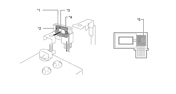
Text in Illustration *1 Current *2 Battery Current Sensor *3 Core *4 Hall IC *5 Battery Temperature Sensor - -
-
-
-
OPERATION
-
Starter Control (Cranking Hold)
-
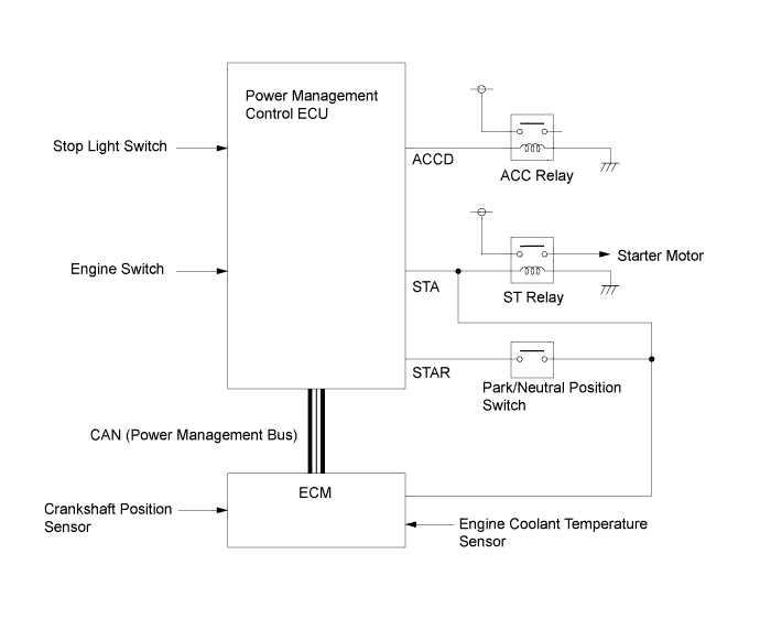
When the engine switch is pressed, the power management control ECU receives a start signal. When the power management control ECU receives this signal, in order to operate the starter, the power management control ECU sends power from its STAR terminal to the starter relay.
-
The power is sent via the park/neutral position switch when the shift lever is in either P or N. At this time, the power management control ECU turns off the ACC relay by turning off the power sent from the ACCD terminal. The ACC relay is turned off to prevent flickering of the meters, clock and audio system.
-
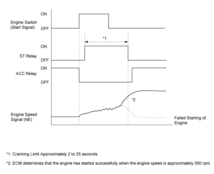
While cranking, the power management control ECU continues energizing the starter relay until it is determined that the engine has started. The power management control ECU and ECM are both used to judge if the engine has started. When it has been judged that the engine has started, the power management control ECU stops energizing the starter relay.
-
If the engine does not start, the starter operates for a length of time that is based on coolant temperature. This can range from 25 seconds at lower temperatures to 2 seconds when the engine is at operating temperature.
-
This system has following safety features:
-
While the engine is running, the starter cannot operate.
-
The starter will stop operating once the engine has started, even if the engine switch remains pushed.
-
Starter operation is limited to a maximum of 30 seconds to protect the starter motor.
-
The starter will stop if the ECM cannot detect an engine speed signal (NE) while the starter is operating.
-
-
-
Charging Control
-
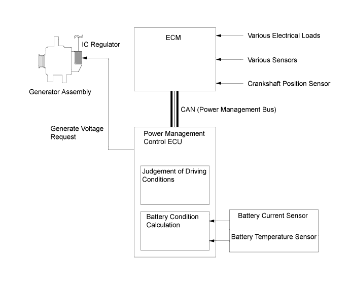
Charging control regulates the generated voltage of the generator assembly in accordance with driving conditions to help achieve improved fuel economy. Voltage generation is prioritized while decelerating. During constant-speed driving, battery charging and discharging are repeated to maintain a constant battery charge level.
-
The ECM receives signals from various sensors and switches, and transmits them to the power management control ECU.
-
The power management control ECU received the signals and detects charging condition based on signals from the battery current sensor and battery temperature sensor.
-
Then the power management control ECU outputs the signals to the IC regulator to control the generated voltage of the generator assembly.
-
-
-
FAIL-SAFE
-
In accordance with sensor malfunctions, battery condition and operation of electrical loads, the power management control ECU stops charging control and switches to constant-voltage generation. The switching conditions are as follows:
-
Battery charge level is low or battery fluid temperature is low/high.
-
The wiper motor is operating.
-
The headlights are on.
-
The blower motor is operating on high.
-
A battery current sensor or battery temperature sensor malfunction has occurred.
-
The engine is being started.
-
2 hours have elapsed since charging control started.
-
20 hours of driving time have accumulated.
-
A communication malfunction has occurred.
-
-