POWER STEERING SYSTEM DETAILS
-
FUNCTION OF MAIN COMPONENTS
Component Function Steering Column Assembly Power Steering Torque Sensor Detects the amount of twist of the torsion bar. Based on the torque that is applied to the torsion bar, the sensor creates an electrical signal, and outputs this signal to the power steering ECU. Power Steering Motor Generates power assist in accordance with a signal received from the power steering ECU. Rotation Angle Sensor Outputs the rotation angle of the power steering motor to the power steering ECU. Reduction Mechanism Reduces the speed of the power steering motor through the use of a worm gear and a wheel gear and transmits it to the column shaft. Combination Meter Assembly EPS Warning Light Illuminate to alert the driver when the power steering ECU detects a malfunction in the EPS system. Master Warning Light Illuminate to alert the driver when the power steering ECU detects a malfunction in the EPS system. Power Steering ECU Actuates the power steering motor mounted on the steering column assembly to provide power assist, based on the signals received from various sensors and ECUs. ECM Outputs the engine speed signal to the power steering ECU. Skid Control ECU (Brake Actuator Assembly)
-
Outputs the vehicle speed signal to the power steering ECU.
-
Requests steering torque assist during steering cooperative control.
-
-
SYSTEM CONTROL
-
The EPS system has the following controls:
Control Outline Basic Control Calculates the assist current from the steering torque value and the vehicle speed, and actuates the power steering motor. Inertia Compensation Control Ensures the starting movement of the power steering motor when the driver starts to turn the steering wheel. Recovery Control During the short interval between the time the driver fully turns the steering wheel and when the wheels try to recover, this control assists the recovery force. Damper Control Regulates the amount of assist when the driver turns the steering wheel while driving at high speeds, thus damping the changes in the yaw rate of the vehicle body. Voltage Boost Control Boosts the battery voltage in the power steering ECU. System Overheat Protection Control Estimates the power steering motor temperature based on the amperage and the current duration. If the temperature exceeds the standard, it limits the amperage to prevent the power steering motor from overheating. Electric Load Control Sends a request to the air conditioning amplifier to stop the operation of the rear defogger, wiper deicer and mirror heaters if the steering wheel is turned when the battery voltage is low. -
Basic Control
-
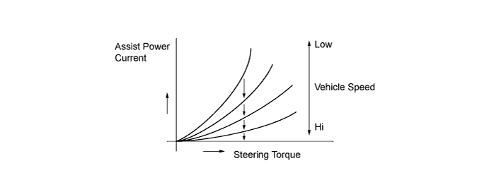
The power steering ECU receives the vehicle speed signal and signals from various sensors. Based on these signals, the power steering ECU judges the current vehicle condition, and determines the assist current to be applied to the power steering motor.
-
The diagram below describes the relationship between the steering torque and the assist power current.
-
-
Electrical Load Control
-
Electrical load control stops the operation of the rear defogger, mirror heaters and wiper deicer* if the steering wheel is turned when the battery voltage is low. This enables the EPS system to ensure its power supply even if the battery voltage is low.
-
The power steering ECU detects the battery voltage, and if the voltage drops to approximately 10 V it sends an electrical load control request to the air conditioning amplifier.
-
Electrical load control is performed as shown below:
Control start conditions
-
Electrical load control starts when both the following conditions are met.
-
Battery voltage is 10 V or less.
-
Steering wheel is being turned.
Control cancellation conditions
-
Electrical load control stops when either the following conditions is met.
-
Steering wheel is not being turned.
-
Battery voltage has recovered to more than 12 V.
*: Except G. C. C countries
-
-
-
-
CONSTRUCTION
-
Steering Column Assembly
-
The steering column assembly includes a power steering torque sensor, power steering motor, and reduction mechanism.
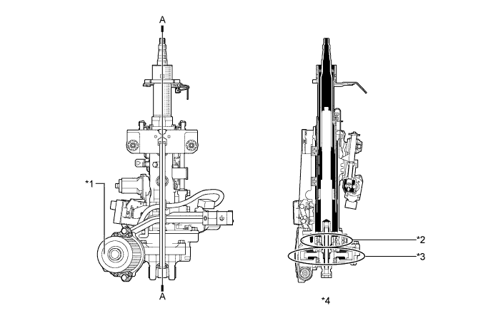
Text in Illustration *1 Power Steering Motor *2 Power Steering Torque Sensor *3 Reduction Mechanism *4 A - A Cross Section -
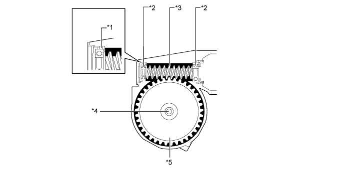
The power steering torque sensor is built into the steering column assembly. A multipole magnet is mounted to the input shaft, and a yoke is mounted to the output shaft. The input and output shafts are joined by a torsion bar.
-
The power steering torque sensor contains 2 Hall ICs which face opposite to each other. The system detects the steering direction in accordance with the direction of the magnetic flux that passes between the Hall ICs. Furthermore, the system detects steering torque in accordance with the amount of change in the magnetic flux density based on the relative displacement of the multipole magnet and the yoke. The power steering ECU monitors the torque sensor signals output by the 2 Hall ICs to detect malfunctions.
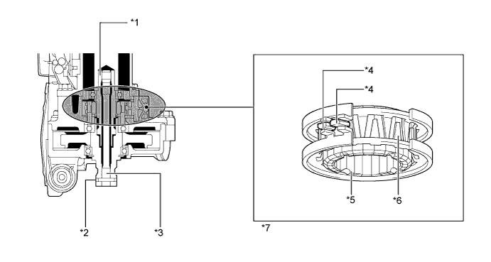
Text in Illustration *1 Input Shaft *2 Output Shaft *3 Torsion Bar *4 Hall IC *5 Multipole Magnet *6 Yoke *7 Power Steering Torque Sensor - - -
A low inertia, low noise, and high power output power steering motor is used.
-
The power steering motor consists of the rotor, stator, motor shaft, and rotation angle sensor.
-
The rotation angle sensor consists of a highly reliable and durable resolver sensor. The rotation angle sensor detects the rotation angle of the motor and outputs it to the power steering ECU. As a result, it ensures efficient EPS control.
-
Torque generated by the motor is transmitted via a joint to the worm gear. This torque is then transmitted via the wheel gear to the column shaft.
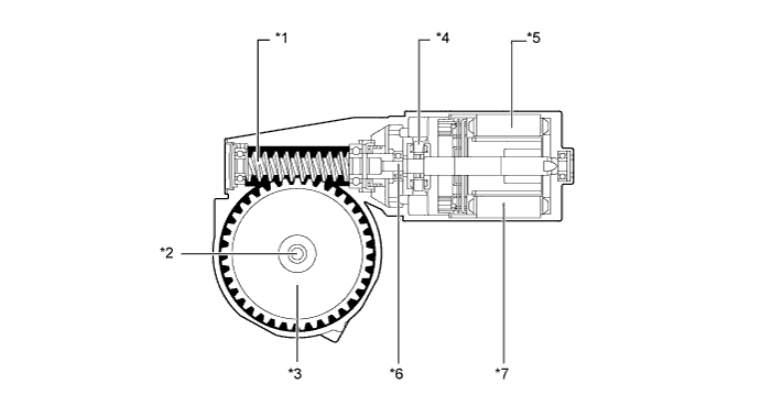
Text in Illustration *1 Worm Gear *2 Column Shaft *3 Wheel Gear *4 Rotation Angle Sensor *5 Rotor *6 Motor Shaft *7 Stator - - -
A reduction mechanism reduces the speed of the motor via the worm gear and the wheel gear, and transmits steering effort to the column shaft.
-
The wheel gear is made of a high strength, low friction, and low wear plastic, to realize low noise and a lightweight construction.
-
A worm gear supported by ball bearings is used. Also, a flat spring is provided to ensure optimal gear engagement at all times.
Text in Illustration *1 Flat Spring *2 Ball Bearing *3 Worm Gear *4 Column Shaft *5 Wheel Gear - -
-
-
-
OPERATION
-
When the steering wheel is not turned
-
If the vehicle is driven straight and the driver does not turn the steering wheel, the yoke is centered between the N and S poles of the multipole magnet. Thus, no magnetic flux passes between the Hall ICs. In this case, the Hall ICs output a specified voltage to the power steering ECU , to indicate that the steering wheel is in the neutral position. Therefore, current is not applied to the motor.
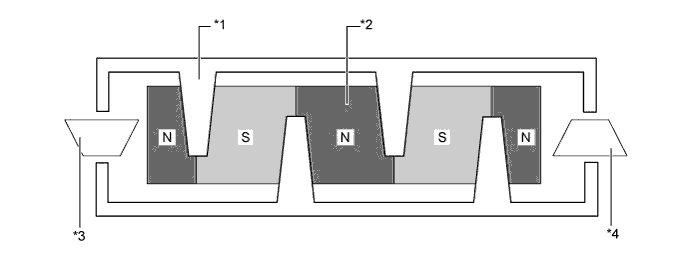
Text in Illustration *1 Yoke Tab *2 Multipole Magnet *3 Hall IC 2 *4 Hall IC 1
-
-
When the steering wheel is turned right or left
-
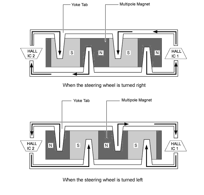
When the driver turns the steering wheel to the right or left, the twist created in the torsion bar creates a relative displacement between the multipole magnet and yoke.
-
At this time, the magnetic flux from the N to S poles of the multipole magnet passes between the Hall ICs. The system detects the direction the steering wheel is being turned in accordance with the direction of the magnetic flux that passes between the Hall ICs. Hall IC1 and Hall IC2 are installed facing opposite to each other. As a result, the output characteristics of the 2 Hall ICs are constantly opposite each other. The system monitors the different outputs of these Hall ICs in order to detect malfunctions.
-
The magnetic flux density becomes higher as the Hall ICs get closer to the center of each respective pole. Each Hall IC converts these magnetic flux fluctuations into voltage fluctuations in order to transmit the rotational torque of the steering wheel to the power steering ECU.
-
-
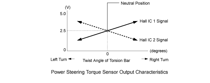
Power Steering Torque Sensor Output Characteristics
-
When the driver does not turn the steering wheel, the power steering torque sensor outputs a specified voltage (2.5 V) to the power steering ECU. As long as the specified voltage is output, the power steering ECU determines that the steering wheel is in the neutral position.
-
When the driver turns the steering wheel to the right or left, the voltage output from the power steering torque sensor to the power steering ECU changes. Based on the changes, the power steering ECU determines the steering torque and steering direction input by the driver.
-
-
-
FAIL-SAFE
-
If the power steering ECU detects a malfunction in the EPS system, the power steering ECU illuminates the EPS warning light.
-
If a system malfunction occurs, the power steering ECU changes control mode to fail-safe mode. Fail-safe operation modes are as follows:
Item Control Power Steering Torque Sensor Malfunction Disables the assist. Power Steering Motor Overcurrent Disables the assist. Power Steering Motor Short (Including drive system malfunction) Disables the assist. Power Steering Motor Rotation Angle Sensor Malfunction Disables the assist. Power Steering ECU Internal Temperature Sensor Malfunction Limits the assist force. Power Steering ECU System Malfunction Disables the assist. Vehicle Speed or Engine Speed Signal Malfunction Limits the assist force. Power Supply Voltage Malfunction Power supply voltage malfunction pauses the assist. (Normal assist is provided after the voltage recovers.)
-
-
DIAGNOSIS
-
If the power steering ECU detects a malfunction in the EPS system, Diagnostic Trouble Codes (DTCs) are stored in the power steering ECU memory.
-
The 5-digit DTCs can be read by connecting the intelligent tester to the DLC3. For details, refer to the Repair Manual.
-
-