BRAKE CONTROL SYSTEM DETAILS
-
FUNCTION OF MAIN COMPONENTS
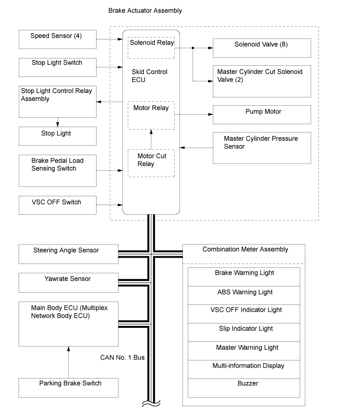
Component Function Brake Actuator Assembly
-
Solenoid Valve
-
Master Cylinder Cut Solenoid Valve
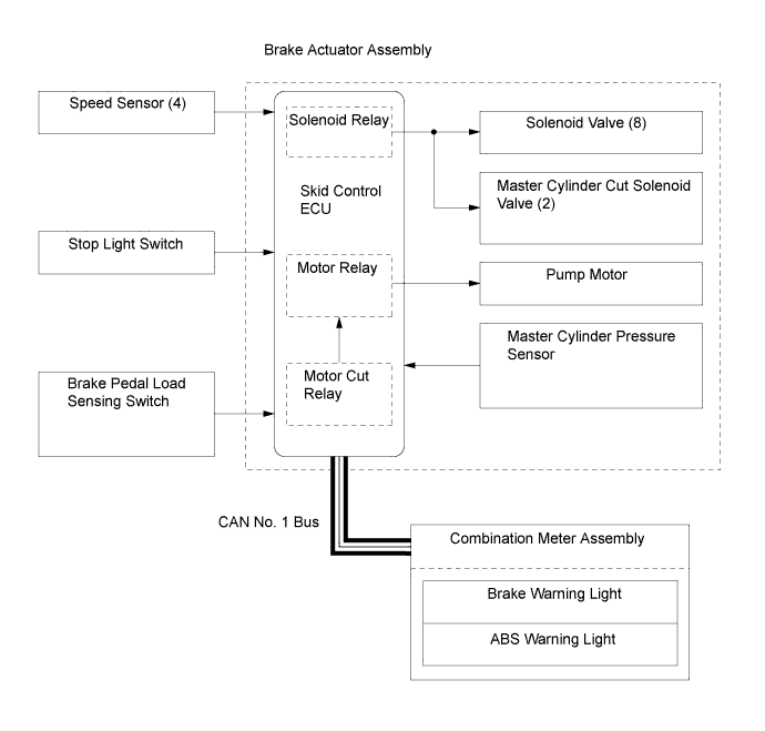
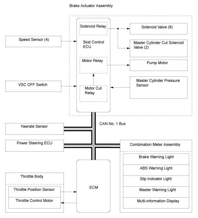
Change the fluid path based on the signals from the skid control ECU during the operation of the brake control system functions in order to control the fluid pressure applied to each wheel cylinder. Master Cylinder Pressure Sensor Assembled in the brake actuator, detects the master cylinder pressure. Skid Control ECU Judges the vehicle driving condition based on the signals from each sensor, and sends the brake control signals to the brake actuator. Motor Relay Supplies power to the pump motor. Solenoid Relay Supplies power to the solenoid valves. Combination Meter Assembly Brake Warning Light
-
Illuminates together with the ABS warning light to alert the driver when the skid control ECU detects a malfunction in the EBD control.
-
Illuminates to alert the driver when the skid control ECU detects a malfunction in the brake booster.
-
Illuminates to alert the driver when the brake fluid level is low.
-
Illuminates to inform the driver when the parking brake is applied.
ABS Warning Light Illuminates to alert the driver when the skid control ECU detects a malfunction in the ABS. Slip Indicator Light
-
Blinks to inform the driver when TRC or VSC is operating.
-
Illuminates to alert the driver when the skid control ECU detects a malfunction in the TRC or VSC systems.
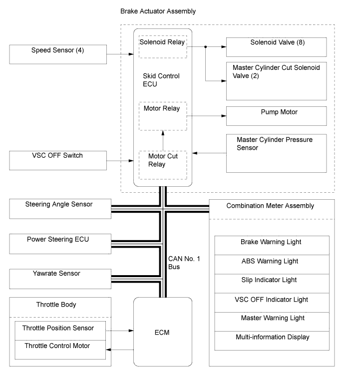
VSC OFF Indicator Light Illuminates to inform the driver when VSC OFF mode is selected. Master Warning Light Illuminates to alert the driver when the skid control ECU detects a malfunction in the brake control system. Multi-information Display
-
Displays a warning message to alert the driver when TRC OFF mode is selected.
-
Displays a warning message to alert the driver when the skid control ECU detects a malfunction in the brake control function.
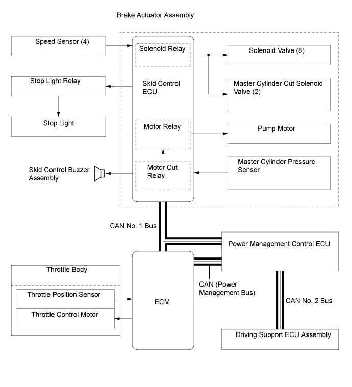
Buzzer Emits a warning sound to inform the driver when Hill-start Assist Control operation is started or finished. Skid Control Buzzer Assembly*1 Emits a warning sound to inform the driver during brake control operation. Stop Light Control Relay Assembly
-
Illuminates the stop lights while Hill-start Assist Control is operating.
-
Blinks the stop lights while emergency stop light control is operating.*2
Steering Angle Sensor Detects the direction and angle of the steering wheel. Yawrate Sensor
-
Detects the vehicle's longitudinal and lateral acceleration and deceleration.
-
Detects the vehicle's yaw rate.
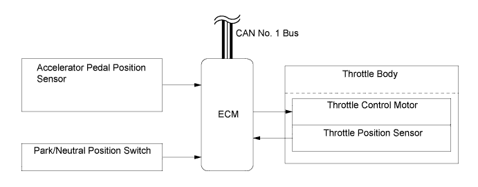
Speed Sensor Detect the wheel speed of each of the 4 wheels. Stop Light Switch Detects brake pedal operation. Brake Pedal Load Sensing Switch Detects the brake pedal depressing force. Parking Brake Switch Detects the parking brake pedal status. VSC OFF Switch Enables the driver to select Normal mode, TRC OFF mode, or VSC OFF mode. Hazard Warning Switch*2 Transmits a hazard warning light on/off request to the main body ECU. Accelerator Pedal Position Sensor Detects the accelerator pedal depression angle. ECM
-
Sends the throttle position signal, accelerator pedal position signal, engine speed signal etc., to the skid control ECU.
-
Based on the signals received from the skid control ECU, controls the engine output.
Main Body ECU (Multiplex Network Body ECU)
-
Detects the parking brake signal and outputs it to the skid control ECU via CAN communication.
-
Detects the hazard switch on/off signal and outputs it to the skid control ECU via CAN communication.*2
Power Management Control ECU The power management control ECU is connected to the various ECU via CAN. Driver Support ECU Assembly*1 Transmits a signal to the skid control ECU, in order to activate brake control when the ECU has determined that the distance to the vehicle being driven ahead has been shortened based on signals from the millimeter wave radar sensor assembly. *1: Models with dynamic radar cruise control system
*2: Models for Europe
-
-
OPERATING CONDITION
-
Emergency Brake Signal
-
Emergency brake signal operating conditions are as shown in the following table.
A) Activating Conditions When all of the following conditions are met, the emergency brake signal starts operating:
-
Vehicle speed is over 55 km/h (35 mph).
-
Driver is depressing the brake pedal.
-
Emergency braking is detected from the vehicle deceleration.
B) Deactivating Conditions When any of the following conditions is met, emergency brake signal stops operating:
-
Driver has released the brake pedal.
-
Emergency braking is no longer detected from the vehicle deceleration.
-
Driver has pressed the hazard warning switch.
-
-
-
-
SYSTEM CONTROL
-
General
-
VDIM and VSC with EPS-VSC Integrated Control consist of the following controls:
Control Outline VDIM VSC with EPS - VSC Integrated Control Steering Cooperative Control Effects cooperative control with the power steering ECU in order to provide steering assist in accordance with vehicle conditions. X X Anti-lock Brake System (ABS) The ABS helps prevent the wheels from locking when the brakes are applied firmly or when braking on a slippery surface. X X Electronic Brake Force Distribution (EBD) EBD control utilizes ABS, realizing proper brake force distribution between the front and rear wheels in accordance with the driving conditions. In addition, during braking while cornering, it also controls the brake forces of the right and left wheels, helping maintain vehicle behavior. X X Brake Assist The primary purpose of Brake Assist is to provide supplementary brake force to assist a driver who cannot generate a large brake force during emergency braking, thus helping ensure the vehicle's braking performance. X X Traction Control (TRC) Helps restrain the slippage of the drive wheels if the driver depresses the accelerator pedal excessively when starting off or accelerating on a slippery surface. X X Limited Slip Differential (LSD) Function The LSD function detects vehicle turning condition and wheel slippage. Then, brake force is applied to the inner wheel to limit slippage and to transmit power to the outer wheels, ensuring acceleration performance during a vehicle turn. X - Vehicle Stability Control (VSC) Helps restrain sideways slippage of the vehicle during a strong understeer tendency or strong oversteer tendency while cornering. X X Hill-start Assist Control When the vehicle starts off on a steep or a slippery hill, Hill-start Assist Control detects the backward movement of the vehicle and performs 4-wheel hydraulic pressure control to prevent the vehicle from moving backward. X X Brake Control*1 During dynamic radar cruise control system operation, if the distance to the vehicle being driven ahead is reduced, 4-wheel hydraulic pressure control is used to apply the brakes according to the driving support ECU assembly request. X X Brake Control*2 When the driving support ECU assembly determines a high possibility of collision, the skid control ECU activates the pre-crash brake assist or the pre-crash brake according to the signal from the driving support ECU assembly. X X Emergency Brake Signal In the case of emergency braking, the emergency brake signal flashes the stoplights to alert the drivers in following vehicles. X*3 -
-
X: Equipped
-
-: Not equipped
*1: Models with dynamic radar cruise control system
*2: Models with pre-crash brake
*3: Models for Europe
-
-
-
Steering Cooperative Control
-
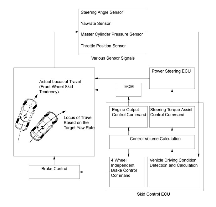
Steering cooperative control performs coordinated control using both VSC and EPS. By integrating these active safety functions, excellent driving stability and maneuverability are secured.
-
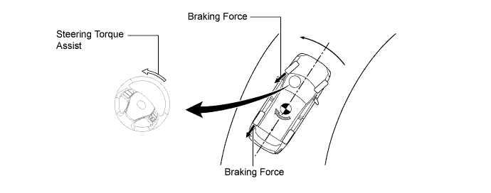
If the vehicle loses stability due to wheel slippage, this function performs brake control by applying brake pressure to each individual wheel while at the same time, the EPS provides steering torque assist control to facilitate the driver's steering maneuver.
-
When braking on a split friction road, the vehicle tends to deflect toward the higher friction side due to the difference between the brake force on the left and right sides. In this state, the power steering ECU receives command signals from the skid control ECU. Based on these signals, the power steering ECU operates the EPS motor to reduce the effect of this brake force difference on either side, assisting the driver in making corrective steering operations.
-
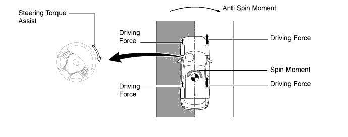
When accelerating on a split friction road, the vehicle tends to deflect toward lower friction side due to the drive force difference between the left and right sides. In this state, the skid control ECU performs brake control of the drive wheel on the low friction side (TRC function) and transmits command signals to the power steering ECU. Based on these signals, the power steering ECU operates the EPS motor to reduce the effect of this drive force difference on either side, assisting the driver in making corrective steering operations. As a result, ideal drive force control and vehicle stability is ensured.
-
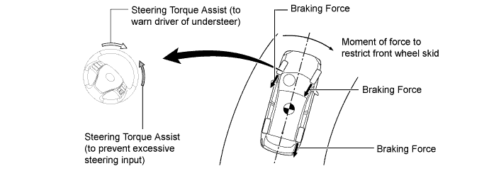
When under steer (front wheel skid) is detected, engine output is limited and brake control is performed based on the amount of understeer tendency. Accordingly, a moment of force is generated in the vehicle turning direction to limit the understeer tendency.
-
Steering torque assist is also provided to warn the driver of understeer.
-
If the driver turns the steering wheel excessively, steering torque assist is provided to prevent excessive steering input.
-
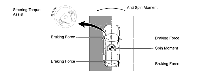
When oversteer (rear wheel skid) is detected, brake force is applied to mainly the outer wheels based to the amount of oversteer tendency. Accordingly, an anti-spin moment is generated to limit the oversteer tendency.
-
In this state, the power steering ECU receives command signals from the skid control ECU. Based on these signals, the power steering ECU operates the EPS motor to compensate for the oversteer tendency, assisting the driver in making corrective steering operations.
-
-
Anti-lock Brake System (ABS)
-
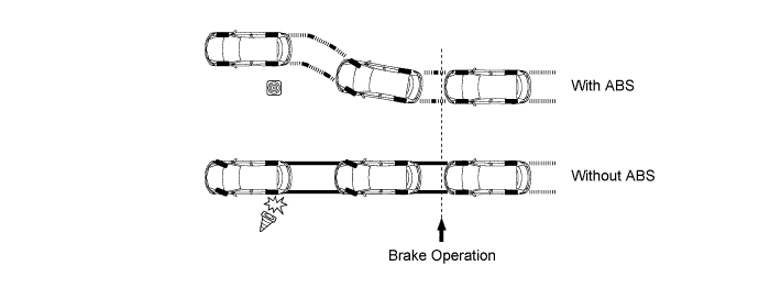
The ABS prevents the wheels from locking during sudden braking or braking on a slippery surface. This provides ideal brake force when the vehicle slips, thus ensuring vehicle stability and excellent braking performance.
-
-
Electronic Brake Force Distribution (EBD)
-
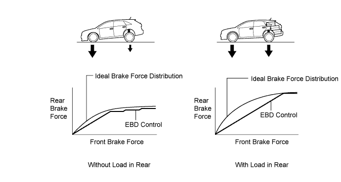
This function controls the brake force acting on the rear wheels in accordance with changes in the vehicle condition such as load factors or deceleration in order to ensure excellent braking performance.
-
When braking while cornering, this function controls the brake force acting on each individual wheel in accordance with present vehicle behavior. This ensures vehicle stability and excellent braking performance.
-
-
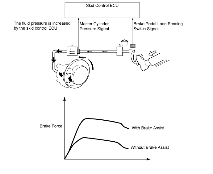
Brake Assist
-
With brake assist, based on the signals from the master cylinder pressure sensor, the skid control ECU calculates the amount the brake pedal is applied and the speed at which it is depressed to determine if the driver is attempting emergency braking. If the skid control ECU determines that the driver is attempting emergency braking, the brake assist function activates the brake actuator to increase the brake fluid pressure, which increases the brake force.
-
-
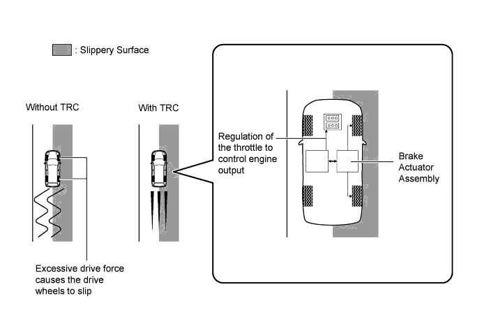
Traction Control (TRC)
-
TRC helps prevent the drive wheels from slipping if the driver depresses the accelerator pedal excessively when starting off or accelerating on a slippery surface. Used simultaneously with hydraulic brake control over the drive wheels, the skid control ECU requests the ECM to perform engine output control. This produces drive force suited to the driving conditions in order to ensure proper start-off acceleration.
-
-
Limited Slip Differential (LSD) Function
-
When the vehicle accelerates around a turn, the load shifts to the outside of the turn. This hinders the transfer of drive force from the inner wheels to the road surface, allowing the inside wheels to spin.
-
The LSD function detects the vehicle's turning condition and wheel slippage. Brake force is then applied to the inner wheels to limit slippage and transmit power to the outer wheels, ensuring acceleration inline with the driver's intentions.
-
When the engine output is restricted on muddy roads and in deep snow, etc. and a drop occurs in escape performance, engine output control can be stopped by pressing the VSC OFF switch, and departure performance can be ensured.

-
-
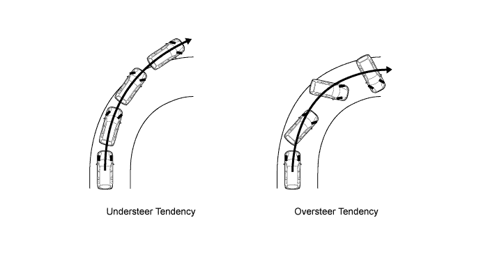
Vehicle Stability Control (VSC)
-
The following 2 examples can be considered as circumstances in which the tires exceed their lateral grip limit. VSC is designed to help control the vehicle behavior by controlling the engine output and the brakes at each wheel when the vehicle is subject to one of the conditions indicated below.
-
To determine the condition of the vehicle, sensors detect the steering angle, vehicle speed, vehicle's yaw rate, and the vehicle's lateral acceleration, which are then calculated by the skid control ECU.
-
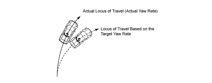
Whether or not the vehicle is experiencing understeer is determined by the difference between the target yaw rate and the vehicle's actual yaw rate. When the vehicle's actual yaw rate is smaller than the target yaw rate (a target yaw rate is determined based on the vehicle speed and steering angle) that should be generated when the driver operates the steering wheel, it means the vehicle is making a turn at a greater angle than the target locus of travel. Thus, the skid control ECU determines that there is a large understeer tendency.
-
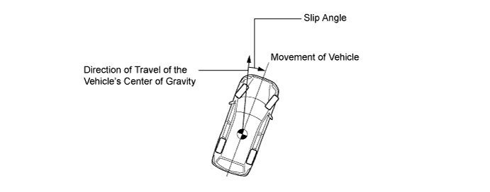
Whether or not the vehicle is experiencing oversteer is determined by the values of the vehicle's slip angle and the vehicle's slip angular velocity (time-dependent changes in the vehicle's slip angle). When the vehicle's slip angle is large, and the slip angular velocity is also large, the skid control ECU determines that the vehicle has a large oversteer tendency.
-
When the skid control ECU determines that the vehicle exhibits a tendency to experience either understeer or oversteer, it decreases the engine output and applies the brakes of individual wheels to control the vehicle's yaw moment. The basic operation of the VSC functions is described below. However, the control method differs depending on the vehicle's characteristics and driving conditions.
-
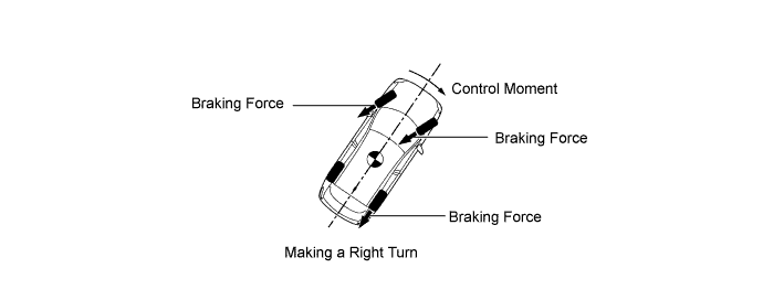
When the skid control ECU determines that there is a large understeer tendency, it takes countermeasures in accordance with the extent of that tendency. The skid control ECU controls engine output and applies the brakes of both front wheels and the rear wheel on the inside of the turn in order to help restrain the understeer tendency.
-
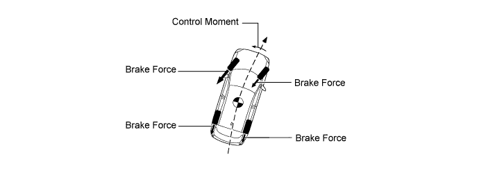
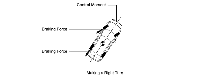
When the skid control ECU determines that there is a large oversteer tendency, it takes countermeasures in accordance with the extent of that tendency. It applies the brake of the front and rear wheels on the outside of the turn to generate an outward moment in vehicle inertia in order to restrain the oversteer tendency. Along with the reduction in the vehicle speed caused by the brake force, excellent vehicle stability is ensured.
-
-
Hill-start Assist Control
-
When the vehicle starts off on a steep or slippery hill, the vehicle could descend backward when the driver switches from the brake pedal to the accelerator pedal, thus making it difficult for the vehicle to start off. To prevent this from occurring, hill-start assist control temporarily (approximately 2 seconds maximum) applies the brakes to all the wheels in order to prevent the vehicle from moving backward.
-
Without hill-start assist control, the driver must quickly and precisely switch from the brake pedal to the accelerator pedal. With hill-start assist control, however, the driver can start off easily and operate the pedal in a relaxed manner because hill-start assist control prevents the vehicle from moving backward.
-
-
Emergency Brake Signal
-
Emergency brake signal automatically flashes all the stop lights in the case of emergency braking in order to reduce the risk of being rear ended by a following vehicle.
-
The skid control ECU detects the vehicle condition and braking operation using speed sensors, the yawrate sensor and stop light switch.
-
Based on these various signals, the skid control ECU sends an instruction to the stop light control relay to flash the stop lights if emergency braking is detected.
-
-
-
FUNCTION
-
VSC OFF Switch
-
Using the VSC OFF switch can stop the operation of the VSC and TRC functions. This is used to stop engine output control and maintain drive torque when driving on the shoulder or on dirt roads.
-
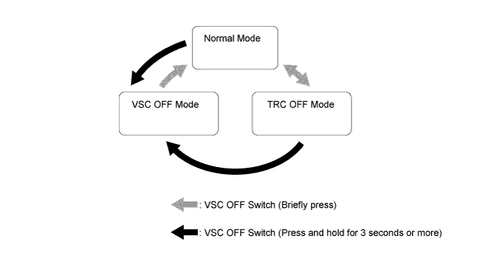
The VSC OFF switch can select 3 modes (Normal mode, TRC OFF mode, VSC OFF mode).
-
After the engine switch is turned off in TRC OFF mode or VSC OFF mode, turning the engine switch ON again selects normal mode.
-
The operations of the brake control functions in each mode are as follows:
Item Brake Control Function Multi-information Display VSC OFF Indicator Light TRC VSC Normal Mode Controllable Controllable - - TRC OFF Mode X Controllable TRC OFF message is displayed - VSC OFF Mode X X* TRC OFF message is displayed Illuminates
-
X: Not controllable
-
-: Not displayed or not illuminated
*: Control will be performed during braking or if the yaw rate is excessive.
-
-
-
-
CONSTRUCTION
-
Steering Angle Sensor
-
The steering angle sensor detects the steering direction and angle, and sends this signal to the skid control ECU.

-
-
Yawrate Sensor
-
The yawrate sensor detects the vehicle's yaw rate.
-
The deceleration sensor detects longitudinal acceleration and deceleration.

Tech Tips
After replacing the yawrate sensor, or skid control ECU, initialization of the yawrate sensor is required. For the details, refer to the Repair Manual.
-
-
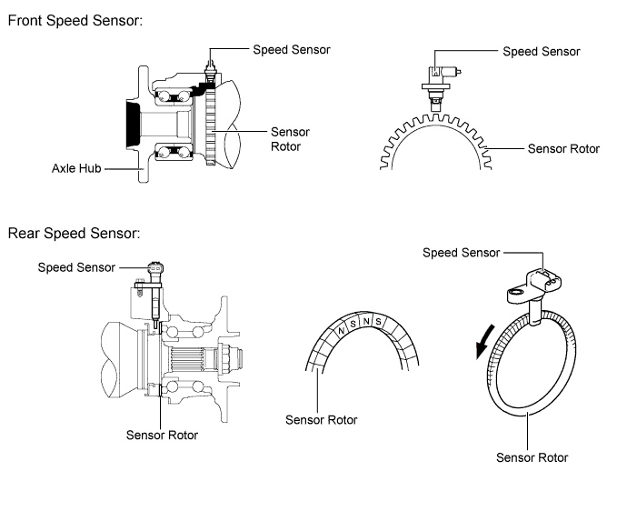
Speed Sensor
-
An active type speed sensor is used. This sensor contains a Hall IC.
-
The magnet type rotor, which consists of N and S poles arranged in a circle, is integrated with the hub bearing inner race.
-
-
Brake Actuator Assembly
-
The brake actuator assembly consists of the brake actuator portion and skid control ECU.
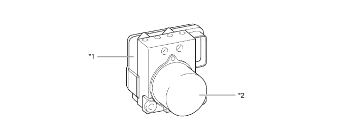
Text in Illustration *1 Skid Control ECU *2 Brake Actuator Portion -
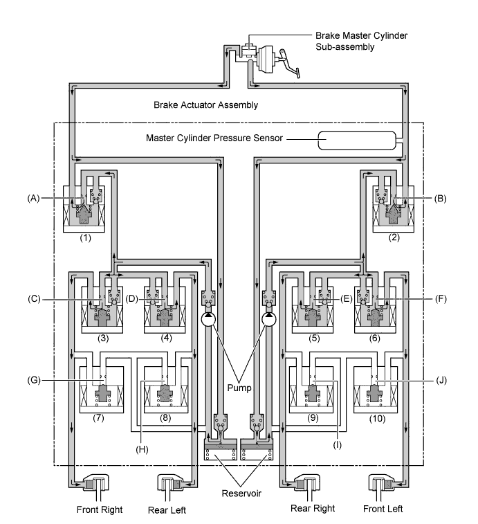
The brake actuator is constructed with the following hydraulic circuit:
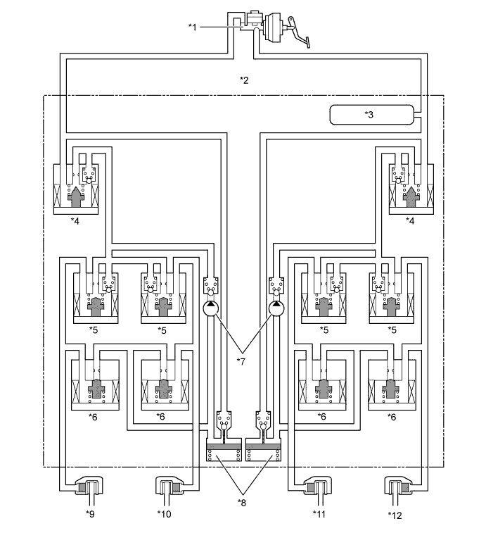
Text in Illustration *1 Brake Master Cylinder Sub-assembly *2 Brake Actuator Assembly *3 Master Cylinder Pressure Sensor *4 Master Cylinder Cut Solenoid Valve *5 Pressure Holding Solenoid Valve *6 Pressure Reduction Solenoid Valve *7 Pump *8 Reservoir *9 Front Brake Caliper (Right Side) *10 Rear Brake Caliper (Left Side) *11 Rear Brake Caliper (Right Side) *12 Front Brake Caliper (Left Side)
-
-
-
OPERATION
-
Speed Sensor
-
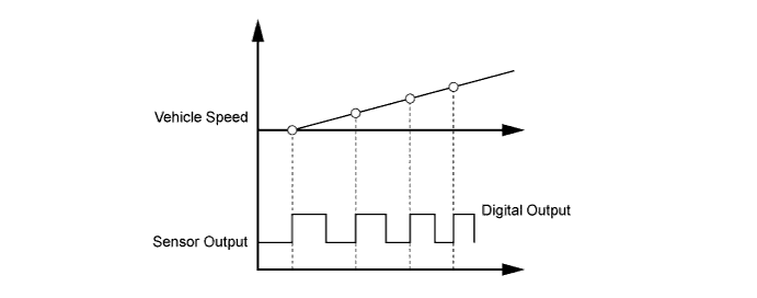
An active type speed sensor uses a sensor IC to detect magnetic field changes caused when the sensor rotor rotates, and the sensor outputs the detected information to the skid control ECU as digital pulses (vehicle speed signal).
-
To detect the vehicle speed, the frequency of the output pulses is used. Because the active type sensor outputs digital pulses, it can detect vehicle speeds even when the vehicle is nearly stationary.
-
-
ABS and EBD
-
Based on the signals received from the 4 speed sensors, the skid control ECU calculates each wheel speed and deceleration, and checks wheel slipping conditions. According to the slipping condition, the skid control ECU controls the pressure holding valve and pressure reduction valve in order to adjust the fluid pressure of the each wheel cylinder in the following 3 modes: pressure reduction, pressure holding, and pressure increase modes.
Not Activated Normal Braking - - Activated Increase Mode Holding Mode Reduction Mode Hydraulic Circuit 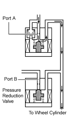
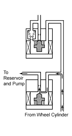
Pressure Holding Valve (Port A) OFF (Open) ON (Closed) ON (Closed) Pressure Reduction Valve (Port B) OFF (Closed) OFF (Closed) ON (Open) Brake Wheel Cylinder Pressure Increased Held Reduced
-
-
Brake Assist
-
In the event of emergency braking, the skid control ECU determines the driver's intentions based on the speed of the pressure increase in the master cylinder detected by the master cylinder pressure sensor signal. If the skid control ECU judges the need for additional brake assist, pressure to supplement the amount provided by the master cylinder is generated by the pump in the brake actuator and directed to each wheel cylinder.
-
The skid control ECU also provides brake assist in the event of a brake booster failure. The skid control ECU judges a brake booster failure using the brake load sensing switch and master cylinder pressure sensor signals.
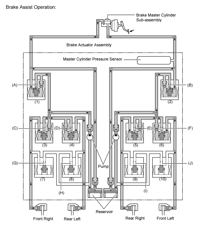
Item Port Brake Assist Not Activated Brake Assist Activated Master Cylinder Cut Solenoid Valves (1), (2) (A), (B) OFF (Open) ON* Pressure Holding Solenoid Valves (3), (4), (5), (6) (C), (D), (E), (F) OFF (Open) OFF (Open) Pressure Reduction Solenoid Valves (7), (8), (9), (10) (G), (H), (I), (J) OFF (Closed) OFF (Closed) Pump OFF ON *: The solenoid valves continually change between open and closed according to adjust the hydraulic pressure according to operating conditions.
-
-
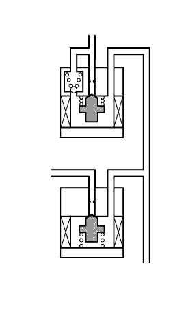
TRC
-
The fluid pressure generated by the pump is regulated by the master cylinder cut solenoid valve to achieve the required pressure. Thus, the brakes for the drive wheels are controlled in the following 3 modes: pressure reduction, pressure holding, and pressure increase modes, to control slippage of the drive wheels.
-
The diagram shows the hydraulic circuit in the pressure increase mode when TRC is activated. The pressure holding solenoid valve and the pressure reduction solenoid valve are turned ON/OFF according to the ABS and EBD operation pattern.
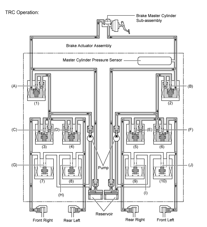
Item Port TRC Not Activated TRC Activated Increase Mode Holding Mode Reduction Mode Master Cylinder Cut Solenoid Valve (1), (2) (A), (B) OFF (Open) ON* ON* ON* Front Brakes Pressure Holding Solenoid Valve (3), (6) (C), (F) OFF (Open) OFF (Open) ON (Closed) ON (Closed) Pressure Reduction Solenoid Valve (7), (10) (G), (J) OFF (Closed) OFF (Closed) OFF (Closed) ON (Open) Brake Wheel Cylinder Pressure Right - - - Increased Held Reduced Left - - - Increased Held Reduced Rear Brakes Pressure Holding Solenoid Valve (4), (5) (D), (E) OFF (Open) OFF (Open) ON (Closed) ON (Closed) Pressure Reduction Solenoid Valve (8), (9) (H), (I) OFF (Closed) OFF (Closed) OFF (Closed) ON (Open) Brake Wheel Cylinder Pressure Right - - - Increased Held Reduced Left - - - Increased Held Reduced Pump OFF ON ON ON *: The solenoid valves continually change between open and closed according to adjust the hydraulic pressure according to operating conditions.
-
-
VSC
-
VSC, by way of solenoid valves, controls the fluid pressure generated by the pump and applies it to each wheel cylinder in the following 3 modes: pressure reduction, pressure holding, and pressure increase modes. As a result, understeer and oversteer tendencies are controlled.
-
In understeer restraining control, the skid control ECU controls engine output and applies the brakes of both front wheels and the rear wheel on the inside of the turn. Also, depending on whether the brakes are applied and the vehicle condition, there are circumstances in which the brake of a specific wheel may not be applied even if it was targeted for braking. The diagram below shows the hydraulic circuit in the pressure increase mode, as it restrains an understeer tendency while the vehicle is making a right turn. In other operating modes, the pressure holding valve and the pressure reduction valve are turned ON/OFF according to the ABS and EBD operation pattern.
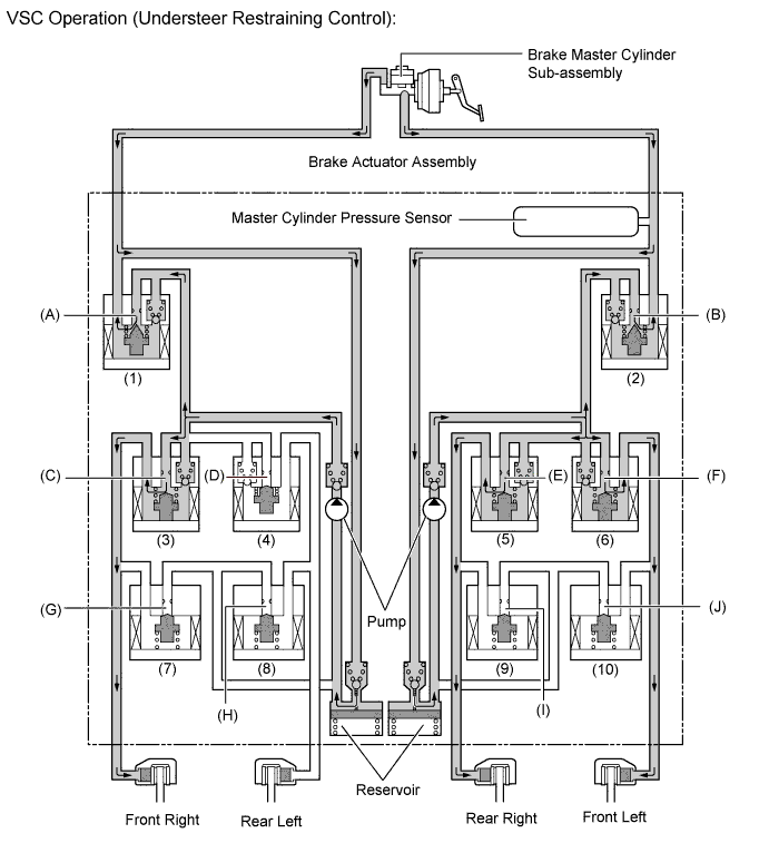
Item Port VSC Not Activated VSC Activated Increase Mode Holding Mode Reduction Mode Master Cylinder Cut Solenoid Valve (1), (2) (A), (B) OFF (Open) ON* ON* ON* Front Brakes Pressure Holding Solenoid Valve (3) (C) OFF (Open) OFF (Open) ON (Closed) ON (Closed) (6) (F) OFF (Open) OFF (Open) ON (Closed) ON (Closed) Pressure Reduction Solenoid Valve (7) (G) OFF (Closed) OFF (Closed) OFF (Closed) ON (Open) (10) (J) OFF (Closed) OFF (Closed) OFF (Closed) ON (Open) Brake Wheel Cylinder Pressure Right - - - Increased Held Reduced Left - - - Increased Held Reduced Rear Brakes Pressure Holding Solenoid Valve (4) (D) OFF (Open) ON (Closed) ON (Closed) ON (Closed) (5) (E) OFF (Open) OFF (Open) ON (Closed) ON (Closed) Pressure Reduction Solenoid Valve (8) (H) OFF (Closed) OFF (Closed) OFF (Closed) OFF (Closed) (9) (I) OFF (Closed) OFF (Closed) OFF (Closed) ON (Open) Brake Wheel Cylinder Pressure Right - - - Increased Held Reduced Left - - - - - - Pump OFF ON ON ON *: The solenoid valves continually change between open and closed according to adjust the hydraulic pressure according to operating conditions.
-
In oversteer restraining control, the skid control ECU applies the brakes of the front and rear wheel on the outside of the turn. Also, depending on whether the brakes are applied and the vehicle condition, the brake of a specific wheel may not be applied even if it was targeted for braking. The diagram below shows the hydraulic circuit in the pressure increase mode, as it restrains an oversteer tendency while the vehicle is making a right turn. In other operating modes, the pressure holding valve and the pressure reduction valve are turned ON/OFF according to the ABS and EBD operation patterns.
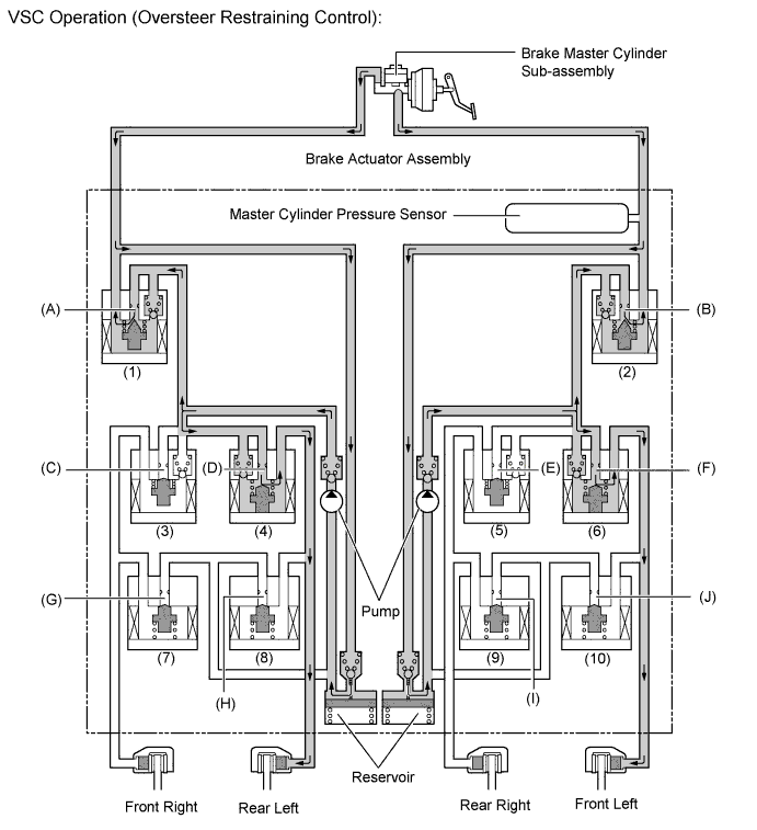
Item Port VSC Not Activated VSC Activated Increase Mode Holding Mode Reduction Mode Master Cylinder Cut Solenoid Valve (1), (2) (A), (B) OFF (Open) ON* ON* ON* Front Brakes Pressure Holding Solenoid Valve (3) (C) OFF (Open) ON (Closed) ON (Closed) ON (Closed) (6) (F) OFF (Open) OFF (Open) ON (Closed) ON (Closed) Pressure Reduction Solenoid Valve (7) (G) OFF (Closed) OFF (Closed) OFF (Closed) OFF (Closed) (10) (J) OFF (Closed) OFF (Closed) OFF (Closed) ON (Open) Brake Wheel Cylinder Pressure Right - - - - - - Left - - - Increased Held Reduced Rear Brakes Pressure Holding Solenoid Valve (4) (D) OFF (Open) OFF (Open) ON (Closed) ON (Closed) (5) (E) OFF (Open) ON (Closed) ON (Closed) ON (Closed) Pressure Reduction Solenoid Valve (8) (H) OFF (Closed) OFF (Closed) OFF (Closed) ON (Open) (9) (I) OFF (Closed) OFF (Closed) OFF (Closed) OFF (Closed) Brake Wheel Cylinder Pressure Right - - - - - - Left - - - Increased Held Reduced Pump OFF ON ON ON *: The solenoid valves continually change between open and closed according to adjust the hydraulic pressure according to operating conditions.
-
-
Hill-start Assist Control Operation
-
Hill-start Assist Control helps maintain 4-wheel hydraulic pressure by operating the master cylinder cut solenoid valve from when the driver releases the brake pedal until depressing the accelerator pedal.
-
Based on the information provided by various sensors, switches, and the ECM, the skid control ECU determines whether to activate Hill-start Assist Control.
-
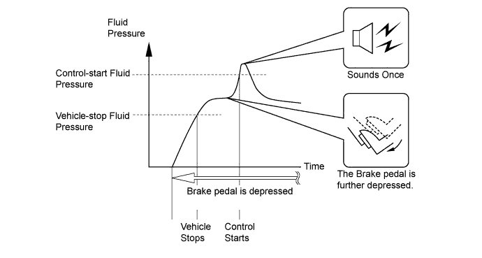
The skid control ECU starts Hill-start Assist Control operation when the operating conditions below are met and the driver further depresses the brake pedal, causing the hydraulic pressure to exceed the control-start hydraulic pressure.
-
When Hill-start Assist Control operation starts, the buzzer in the combination meter assembly will sound once.
Hill-start Assist Control Operating Conditions
-
Shift lever is in a position other than P.
-
The accelerator pedal is not depressed.
-
The vehicle is at a standstill.
-
The parking brake is not applied.
-
-
During Hill-start Assist Control, the slip indicator light blinks and the stop lights are illuminated.
-
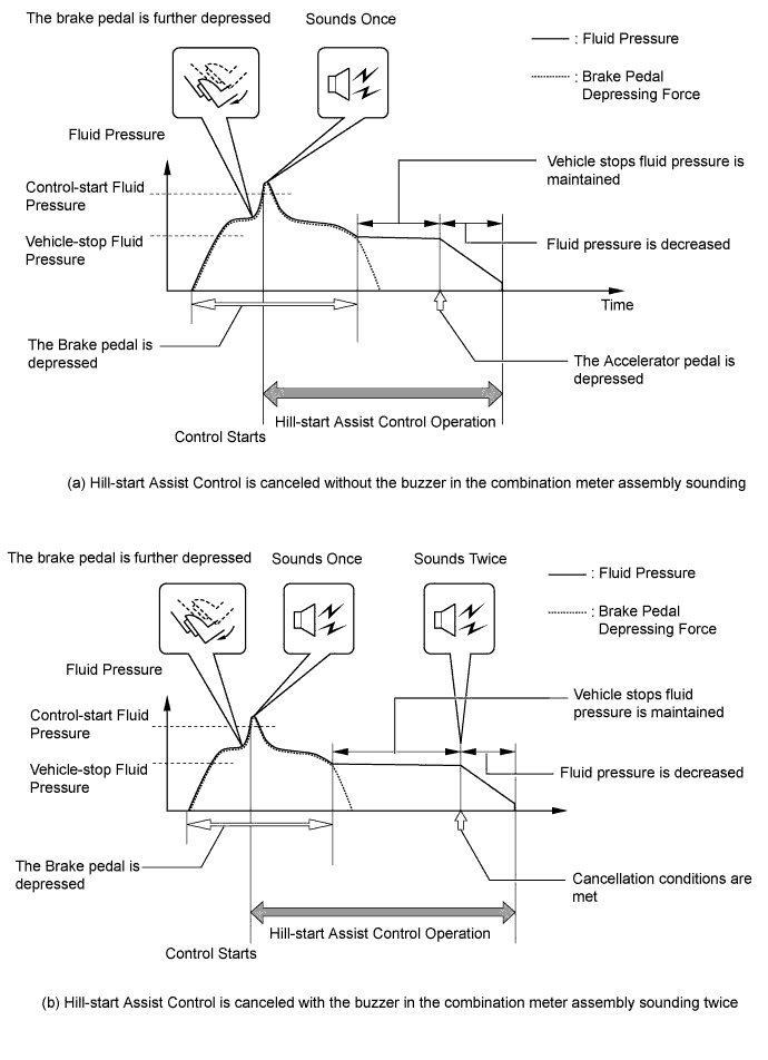
If any one of the below conditions is met during Hill-start Assist Control operation, Hill-start Assist Control will be cancelled causing the slip indicator light to turn off.
-
The buzzer in the combination meter assembly will operate as indicated below when Hill-start Assist Control is cancelled.
CAUTION:
-
The buzzer that indicates the start of Hill-start Assist Control may not sound if the buzzer of the combination meter assembly is already sounding due to other buzzer operation conditions. Even if the buzzer does not sound, the slip indicator light will still start flashing and Hill-start Assist Control will start operating.
-
The buzzer that indicates the cancellation of Hill-start Assist Control may not sound if the buzzer of the combination meter assembly is already sounding due to other buzzer operation conditions. Even if the buzzer does not sound, the slip indicator light will stop flashing and Hill-start Assist Control will stop operating.
Conditions which cause Hill-start Assist Control operation to be canceled a) Buzzer in combination meter assembly does not sound
-
The driver depresses the accelerator pedal.
b) Buzzer in combination meter assembly sounds twice
-
The driver moves the shift lever to P.
-
The driver depresses the parking brake pedal.
-
The driver depresses the brake pedal.
-
The driver releases the brake pedal for several seconds.
-
The driver keeps the brake pedal depressed continually for 3 minutes.
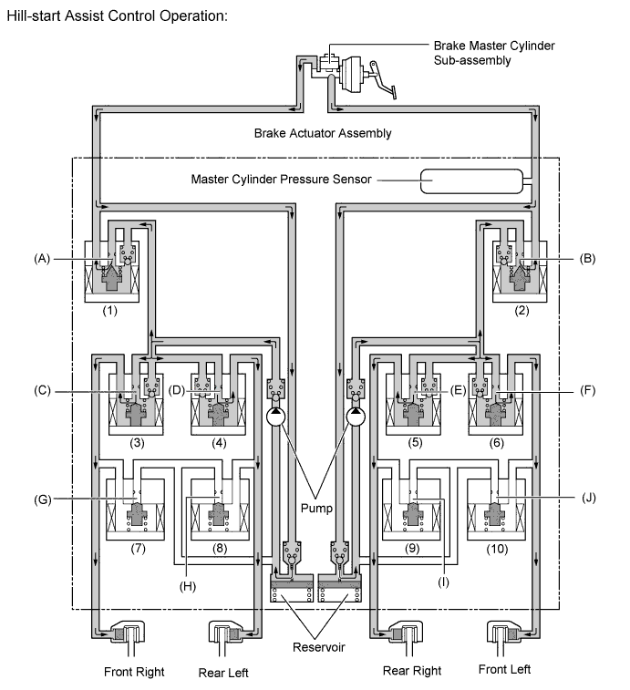
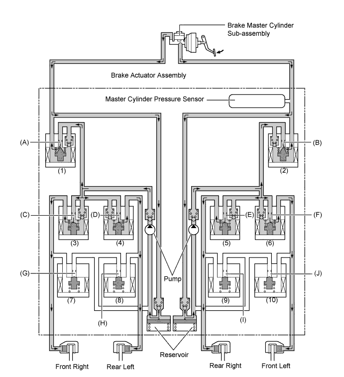
Item Port Hill-start Assist control Not Activated Hill-start Assist Control Activated Holding Mode Reduction Mode Master Cylinder Cut Solenoid Valve (1), (2) (A), (B) OFF (Open) ON* ON* Front Brakes Pressure Holding Solenoid Valve (3), (6) (C), (F) OFF (Open) OFF (Open) OFF (Open) Pressure Reduction Solenoid Valve (7), (10) (G), (J) OFF (Closed) OFF (Closed) OFF (Closed) Brake Wheel Cylinder Pressure Right - - - Held Reduced Left - - - Held Reduced Rear Brakes Pressure Holding Solenoid Valve (4), (5) (D), (E) OFF (Open) OFF (Open) OFF (Open) Pressure Reduction Solenoid Valve (8), (9) (H), (I) OFF (Closed) OFF (Closed) OFF (Closed) Brake Wheel Cylinder Pressure Right - - - Held Reduced Left - - - Held Reduced Pump OFF ON ON *: The solenoid valves continually change between open and closed according to adjust the hydraulic pressure according to operating conditions.
-
-
-
Brake Control Operation (Operating Dynamic Radar Cruise Control)
-
The skid control ECU operates the brakes by receiving a motive force request signal from the driving support ECU assembly while the dynamic radar cruise control system is being activated. This brake control operates in the same way as the normal brake operation.
Item Port Brake Control Not Activated Brake Control Activated Master Cylinder Cut Solenoid Valves (1), (2) (A), (B) OFF (Open) ON* Pressure Holding Solenoid Valves (3), (4), (5), (6) (C), (D), (E), (F) OFF (Open) OFF (Open) Pressure Reduction Solenoid Valves (7), (8), (9), (10) (G), (H), (I), (J) OFF (Closed) OFF (Closed) Pump OFF ON *: The solenoid valves continually change between open and closed according to adjust the hydraulic pressure according to operating conditions.
-
-
Brake Control Operation (Operating Pre-crash Brake)
-
When the driver depresses the brake pedal while the skid control ECU is switched to brake assist standby mode, brake assist control will operate even if the application of the brakes is not considered emergency braking. At this time, the brake control is performed in the same way as the normal brake assist operation.
Item Port Brake Control Not Activated Brake Control Activated Master Cylinder Cut Solenoid Valves (1), (2) (A), (B) OFF (Open) ON* Pressure Holding Solenoid Valves (3), (4), (5), (6) (C), (D), (E), (F) OFF (Open) OFF (Open) Pressure Reduction Solenoid Valves (7), (8), (9), (10) (G), (H), (I), (J) OFF (Closed) OFF (Closed) Pump OFF ON *: The solenoid valves continually change between open and closed according to adjust the hydraulic pressure according to operating conditions.
-
-
-
FAIL-SAFE
-
In the event of a malfunction in the ABS and/or Brake Assist controls, the skid control ECU prohibits brake controls (ABS, Brake Assist, TRC, VSC and Hill-start Assist Control).
-
In the event of a malfunction in the EBD control, the skid control ECU prohibits EBD operation. Even in this case, normal braking performance excluding the brake control system electronic controls (ABS with EBD, Brake Assist, TRC, VSC and Hill-start Assist Control) is maintained.
-
In the event of a malfunction in the TRC and/or VSC, the skid control ECU prohibits TRC and VSC operation.
-
If a communication malfunction occurs among the skid control ECU, the steering angle sensor, the yawrate sensor or ECM, the skid control ECU stops TRC, VSC and Hill-start Assist Control.
-
When the ECM detects an engine control DTC, it will disable ABS, Brake Assist, TRC, VSC and Hill-start Assist Control operation.
-
-
DIAGNOSIS
-
If the skid control ECU detects a malfunction in the brake control system, the ABS, brake system, and/or slip indicator light corresponding to the detected malfunctioning component will illuminate and the multi-information display will display a message as indicated to alert the driver of the malfunction.
-
At the same time, Diagnostic Trouble Codes (DTCs) are stored in memory.
-
This system has a sensor signal check (test mode) function.
-
For details of the DTCs that are stored in skid control ECU memory and the DTCs that are output through the sensor signal check functions, refer to the Repair Manual.
-