SFI SYSTEM PARTS LOCATION
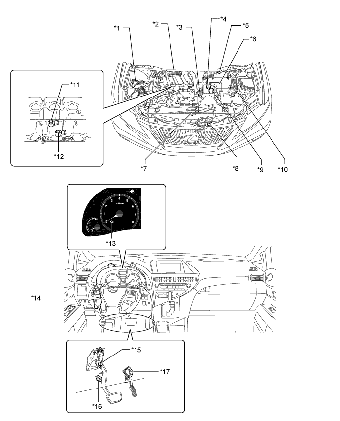
| *1 | Fuel Pump Resistor | *2 | ACIS Actuator |
| *3 | Purge VSV | *4 | VSV (for Air Intake Control) |
| *5 | Mass Air Flow Meter | *6 | Air Cleaner Case Sub-assembly - Vacuum Tank |
| *7 | Cooling Fan ECU | *8 | VSV (for Active Control Engine Mount) |
| *9 | Actuator (for Air Intake Control) | *10 | ECM |
| *11 | Knock Control Sensor (for Bank 1) | *12 | Knock Control Sensor (for Bank 2) |
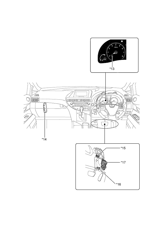
| *13 | Malfunction Indicator Lamp | *14 | Power Management Control ECU |
| *15 | Stop Light Switch | *16 | DLC3 |
| *17 | Accelerator Pedal Rod - Accelerator Pedal Position Sensor |
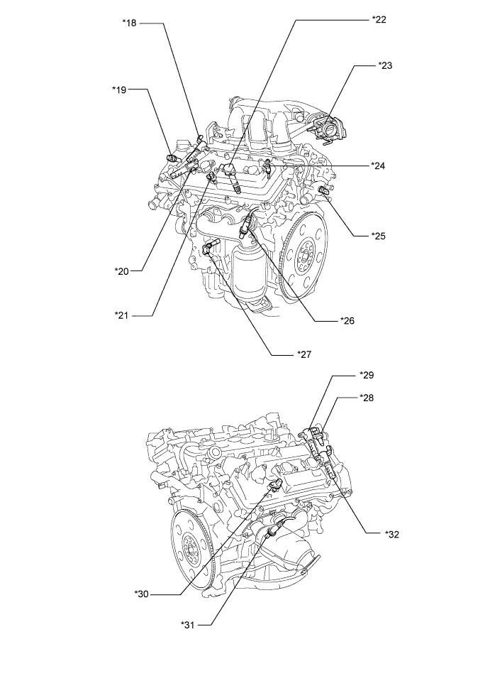
*18 | Camshaft Timing Oil Control Valve Assembly (Intake LH) |
| *19 | Camshaft Position Sensor (Intake LH) | *20 | Camshaft Timing Oil Control Valve Assembly (Exhaust LH) |
| *21 | Camshaft Position Sensor (Exhaust LH) | *22 | Ignition Coil Assembly (with Igniter) |
| *23 | Throttle Body - Throttle Position Sensor - Throttle Control Motor |
*24 | Fuel Injector Assembly |
| *25 | Engine Coolant Temperature Sensor | *26 | Air Fuel Ratio Sensor (Bank 2 Sensor 1) |
| *27 | Crankshaft Position Sensor | *28 | Camshaft Position Sensor (Intake RH) |
| *29 | Camshaft Timing Oil Control Valve Assembly (Intake RH) | *30 | Camshaft Position Sensor (Exhaust RH) |
| *31 | Air Fuel Ratio Sensor (Bank 1 Sensor 1) | *32 | Camshaft Timing Oil Control Valve Assembly (Exhaust RH) |
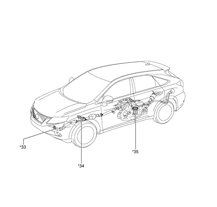
| *33 | Heated Oxygen Sensor (Bank 2 Sensor 2) | *34 | Heated Oxygen Sensor (Bank 1 Sensor 2) |
| *35 | Fuel Pump Assembly | - | - |