LIGHTING SYSTEM DETAILS
-
FUNCTION OF MAIN COMPONENTS
-
LED Headlight System
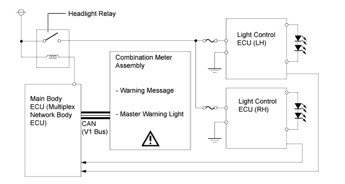
Component Function Headlight Assembly LH/RH Light Control ECU Supplies a constant current to the LED when power is supplied from the No. 1 integration relay. Sends a normal illumination signal to the main body ECU (multiplex network body ECU) while the headlight low beams are illuminated normally. Main Body ECU (Multiplex Network Body ECU)
-
Controls the No. 1 integration relay which supplies power to the light control ECU.
-
Determines a failure in the LED headlight in accordance with the signal from the LED module and light control switch conditions and outputs a warning request signal to the combination meter assembly.
Combination Meter Assembly Multi-information Display Receives the LED headlight warning request signal from the main body ECU (multiplex network body ECU) and displays a warning message. Headlight Indicator Light Illuminates the headlight indicator light while the headlight low beams are illuminated. -
-
Automatic Headlight Beam Level Control System (Models with LED Headlights)
Component Function Headlight Leveling ECU Assembly
-
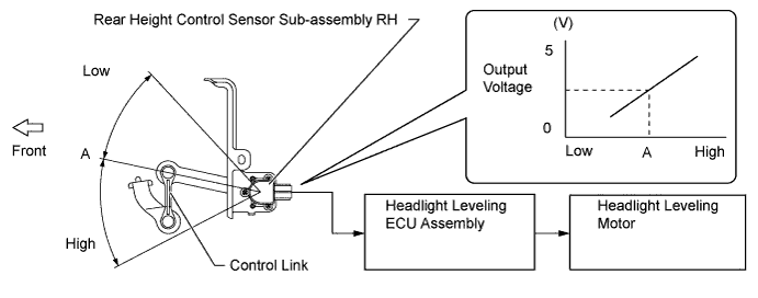
Detects changes in the vehicle movement based on the vehicle speed signals from the rear height control sensor sub-assembly and combination meter assembly.
-
Outputs control signal to the headlight leveling motor.
-
Provides initial set control, fail-safe function and diagnosis function.
Headlight Assembly LH/RH Headlight Leveling Motor
-
Based on the signals received from the headlight leveling ECU assembly, the motors move the reflectors in the headlights.
-
Uses a headlight leveling motor to precisely regulate the angle of the reflectors.
Rear Height Control Sensor Sub-assembly The rear height control sensor sub-assembly detects vehicle movement and transmits a signal to the headlight leveling ECU assembly. Headlight Dimmer Switch Assembly
- Light Control Switch
Transmits the light control switch signal to the main body ECU (multiplex network body ECU). Main Body ECU (Multiplex Network Body ECU) Receives light control switch signal from the light control switch and sends headlight status signals to the headlight leveling ECU assembly. Combination Meter Assembly Headlight Leveling Warning Light When the system malfunctions, the combination meter assembly alerts the driver by illuminating the headlight leveling warning light in accordance with the signals from the headlight leveling ECU assembly. -
-
Automatic Light Control System
Component Function Automatic Light Control Sensor The automatic light control sensor detects the ambient light level. Headlight Dimmer Switch Assembly
- Light Control Switch
Transmits the light control switch signal to the main body ECU (multiplex network body ECU). Main Body ECU (Multiplex Network Body ECU) Receives signals from the automatic light control sensor and AUTO position signals from the light control switch, and illuminates the headlights, taillights, clearance lights and license plate lights. Engine Room Relay Block No. 1 Integration Relay The No. 1 integration relay supplies power to the headlight low beams. Instrument Panel Junction Block Assembly TAIL Relay The TAIL relay supplies power to the taillights, clearance lights and license plate lights. Combination Meter Assembly Taillight Indicator Light The taillight indicator lights up to inform the driver when the taillights turn on. -
Light Auto Turn-OFF System
Component Function Main Body ECU (Multiplex Network Body ECU) Receives various signals, and turns off the exterior lights. Front Door Courtesy Light Switch Assembly Detects whether a door is open or closed and transmits a signal to the main body ECU (multiplex network body ECU). Rear Door Courtesy Light Switch Assembly Back Door Lock Assembly
- Back Door Courtesy Switch
Front Door Lock with Motor Assembly Detects whether a door is locked or unlocked and transmits a signal to the main body ECU (multiplex network body ECU). Rear Door Lock with Motor Assembly Engine Room Relay Block No. 1 Integration Relay The No. 1 integration relay supplies power to the headlight low beams. Instrument Panel Junction Block Assembly TAIL Relay The TAIL relay supplies power to the taillights, clearance lights and license plate lights. FR FOG Relay The FR FOG relay shuts down the power to the front fog lights. Certification ECU (Smart Key ECU Assembly) Judges and certifies the ID code from the door control receiver. Headlight Dimmer Switch Assembly
- Light Control Switch
The light control switch transmits a light control position signal to the main body ECU (multiplex network body ECU). -
Daytime Running Light System
Component Function Main Body ECU (Multiplex Network Body ECU) Receives the READY signal from the power management control ECU and outputs a daytime running light illumination signal to the running light relay. Engine Room Relay Block Running Light Relay Receives the signal from the main body ECU (multiplex network body ECU), performs the high-speed switching operation and then illuminates and dims the high beams. Power Management Control ECU The power management control ECU outputs a READY signal and transmits it to the main body ECU (multiplex network body ECU). Headlight Dimmer Switch Assembly
- Light Control Switch
The light control switch transmits a light control signal to the main body ECU (multiplex network body ECU).
-
-
SYSTEM CONTROL
-
LED Headlight System
-
When the light control switch is turned ON, the light control ECU immediately turns on the LEDs (approximately 0.1 sec). In addition, by regulating the output current flowing into the LEDs at the specified level, the light control ECU prevents the glare of light due to voltage variation.
-
If malfunctions occur in the LED headlight system, the light control ECU transmits failure signals to the main body ECU (multiplex network body ECU). When the main body ECU (multiplex network body ECU) receives failure signals, it transmits signals to the combination meter, warning the driver.
-
-
Automatic Headlight Beam Level Control System (Models with LED Headlights)
-
The rear height control sensor sub-assembly RH detects a change in height of the rear shaft in response to the weight applied to the rear of the vehicle when the vehicle is stopped, and sends the change amount signal to the headlight leveling ECU assembly. The headlight leveling ECU assembly calculates the vehicle posture based on the change amount and controls the headlight beam level by operating the headlight leveling motor.
-
-
Automatic Light Control System
-
The main body ECU (multiplex network body ECU) illuminates or turns off the headlights and taillights at the same time according to the signal from the automatic light control sensor when the power switch is on and the light control switch is in AUTO.
-
-
Light Auto Turn-OFF System
-
While only the taillights are illuminated, the main body ECU (multiplex network body ECU) turns off all of the exterior lights if the driver's door is opened after the power switch is turned off.
-
When the headlights are illuminated, the main body ECU (multiplex network body ECU) turns off all of the exterior lights after approximately 30 seconds have elapsed since any door was opened and then closed after the power switch was turned off.
-
The main body ECU (multiplex network body ECU) turns off all of the exterior lights if the door is locked using a wireless or smart system operation when the power switch was turned off with the headlights still turned on.
Tech Tips
These function settings can be changed using the customized body electronics system. For details, refer to the Repair Manual.
-
-
Daytime Running Light System
-
If the READY signal is output from the power management control ECU to the main body ECU (multiplex network body ECU) when the light control switch and the parking brake pedal are both off, the main body ECU (multiplex network body ECU) activates the DLR relay and illuminates daytime running lights.
-
-
Emergency Brake Signal
-
When all of the following conditions are met, the Emergency Brake Signal starts operating:
-
Vehicle speed is above 55 km/h (34 mph)
-
Driver is depressing the brake pedal
-
Emergency braking is detected from the vehicle deceleration
-
-
When any of the following conditions is met, the Emergency Brake Signal stops operating:
-
Driver has released the brake pedal
-
Emergency braking is no longer detected from the vehicle deceleration
-
Driver has pressed the hazard warning switch
-
-
-
-
CONSTRUCTION
-
LED Headlight System
-
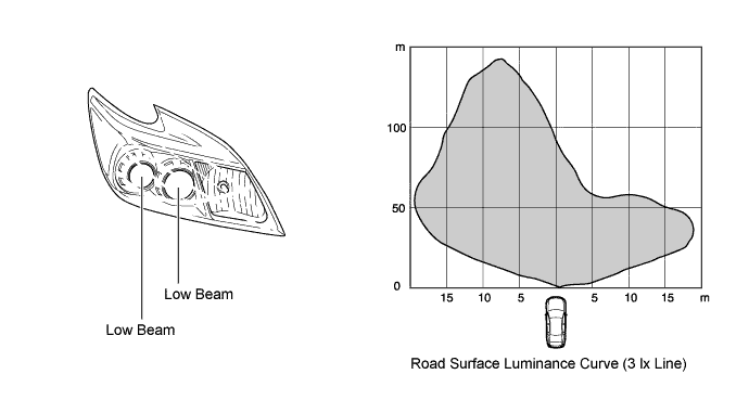
The LED headlight system is used for the low beams, and consists of 2 projector type LED lights.
-
The light from the 2 projector type LED lights is reflected by the reflector and passes through the projector, illuminating an area in the distance. At this time, the illuminated area is optimized by the shape of the reflectors and projector.
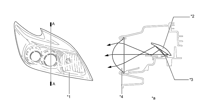
Text in Illustration *1 Headlight Assembly *2 Reflector *3 LED *4 Projector *a A-A Cross Section - -
-
-
Light Control ECU
-
The light control ECUs are placed beneath the headlights. These supply a constant voltage to the low beams and reduces the changes in the energization current.
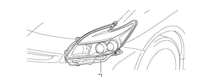
Text in Illustration *1 Light Control ECU - -
-
-
Stop Light Switch
-
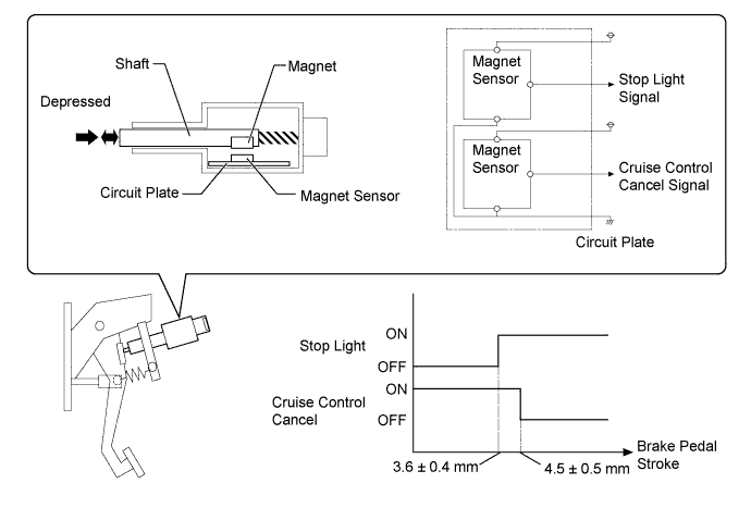
The stop light switch contains a shaft, magnet, 2 magnet sensors and a circuit plate. The magnet is attached to the shaft.
-
When the brake pedal is depressed, the stop light switch shaft and magnet move at the same time. The magnet sensors on the circuit plate detect the extent of the magnet movement and output it in the form of on/off signals. One of the 2 magnet sensors is used for the stop light illumination signal, and the other for the cruise control cancel signal.
Note
Do not place magnets or magnetized objects close to the stop light switch. Placing magnets or magnetized objects close to the stop light switch may adversely affect the characteristics of the switch.
-
-
-
FAIL-SAFE
-
LED Headlight System
-
The light control ECU executes the fail-safe actions listed below in accordance with the problem that has been detected.
Problem Outline Detection of Abnormal Output (Open Circuit or Short Circuit) If an abnormal condition (open or short) occurs in the voltage that is output by light control ECU, the light control ECU stops illuminating the headlight and will maintain this state until power is reinstated. Power is reinstated by turning the light control switch from OFF to ON. Detection of Abnormal Input Voltage If the voltage that is input to the light control ECU deviates from the normal operating voltage (10 - 16 volts), the light control ECU stops illuminating the headlight. It resumes illuminating the headlights once the voltage reverts to the operating voltage range.
-
-
Automatic Headlight Beam Level Control System
-
If an abnormal condition such as those listed below has been detected, the headlight leveling ECU assembly operates in the fail-safe mode. The headlight leveling ECU assembly illuminates the headlight leveling indicator light in the combination meter when a rear height control sensor sub-assembly abnormality has been detected.
Problem Outline Power Supply Voltage Malfunction Holds the beam at the position of the headlight leveling motor when the abnormality had been detected. Rear Height Control Sensor Sub-assembly Power Supply Malfunction Rear Height Control Sensor Sub-assembly Signal Malfunction
-
-
Automatic Light Control System
-
When the main body ECU (multiplex network body ECU) detects a malfunction in the automatic light control sensor, it prohibits the control, however, the system maintains the current illumination state until the light control switch is turned to any position other than AUTO or the power switch is turned off.
Problem Outline Automatic Light Control Sensor Input Frequency Malfunction Determines that there is a malfunction in the automatic light control sensor if the output frequency from the automatic light control sensor lowers below a specified value when the automatic light control sensor power supply is turned on, and stops the control.
-
-
Daytime Running Light System
-
The daytime running light system turns off the daytime running lights to protect the inner circuits if a malfunction occurs in the circuits and a load is applied to the running light relay.
Problem Outline Running Light Relay Overheated Turns off the daytime running light which is overloaded (even if the light is dimmed).
-
-
-
DIAGNOSIS
-
LED Headlight System
-
If the main body ECU (multiplex network body ECU) detects a malfunction in the LED headlight system, the main body ECU (multiplex network body ECU) flashes the master warning light and displays a warning message on the multi-information display. At the same time, a Diagnostic Trouble Code (DTC) is stored in memory.
-
The DTC can be read using the Global TechStream (GTS). For details, refer to the Repair Manual.
-
-
Automatic Headlight Beam Level Control System
-
When the headlight leveling ECU assembly detects malfunctions in the automatic headlight beam level control system, DTCs are stored in memory.
-
The DTCs can be read using the Global TechStream (GTS). For details, refer to the Repair Manual.
-
-
Automatic Light Control System
-
When the main body ECU (multiplex network body ECU) detects malfunctions in the automatic light control system, DTCs are stored in memory.
-
The DTCs can be read using the Global TechStream (GTS). For details, refer to the Repair Manual.
-
-