METER / GAUGE SYSTEM DETAILS
-
OPERATING CONDITION
-
Eco Driving Indicator Light Operation Condition
-
The Eco driving indicator light can begin to operate when all of the following conditions are met:
Condition
-
The READY indicator light is illuminated (the hybrid system is operating).
-
While the vehicle is running.
-
The vehicle is at a speed of 130 km/h (81 mph) or below.
-
The shift position is in D.
-
Power mode is not selected.
-
The EV mode indicator light is turned off.
-
The hybrid system is normal.
-
The hybrid system temperature is normal.
-
-
-
Hybrid System Indicator Operation Condition
-
The hybrid system indicator will begin to operate when both of the following conditions are met:
Condition
-
The READY indicator light is illuminated (the hybrid system is operating).
-
The shift position is in D or B.
-
-
-
-
SYSTEM CONTROL
-
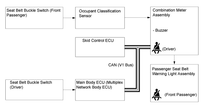
Front Seat Belt Warning
-
The occupant detection sensor, which is enclosed in the seat cushion of the front passenger seat, is used to detect whether or not the front passenger seat is occupied.
-
The front seat belt warning blinks each front seat belt warning light individually when the driver does not fasten the driver seat belt or the front passenger does not fasten the front passenger seat belt.
-
The front seat belt warning buzzer sounds when the vehicle speed reaches approximately 20 km/h (12.4 mph) or more while the front seat belt warning light is blinking. If the seat belt is not then fastened after approximately 30 seconds have elapsed since the buzzer sounded, the front seat belt warning buzzer sounds more loudly than normal for approximately 90 seconds.
-
-
-
FUNCTION
-
Combination Meter
-
The table below shows the combination meter function:
Display Item Outline Fuel Gauge Display Displays the remaining fuel amount. Also, it is capable of displaying the indication accurately when cornering or driving on a steep slope by using a software application capable of suppressing any indication deviations. Speedometer Digitally displays the vehicle speed signal in MPH or km/h. Instantaneous Fuel Consumption Display Displays the instantaneous fuel consumption, which is calculated by the combination meter assembly based on the vehicle speed and the amount of fuel used. Shift Position Display Displays the shift position.
-
-
Multi-information Display
-
The table below shows the multi-information display function:
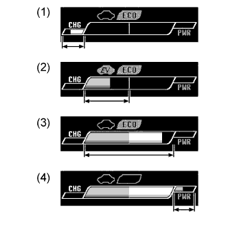
Remaining Battery Amount Display Outline 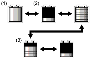
The remaining HV battery amount calculated according to the signal from the power management control ECU is displayed using 2 types of bar graph.
-
The illustration (1) indicates that the HV battery is fully charged. (SOC is full.)
-
When the SOC is lowered to the level shown in (3), the system changes from EV mode to HV mode.
-
When the SOC is returned to the level shown in (2) due to recharging, such as that performed by regenerative braking, HV mode can be changed to EV mode using the EV/HV mode selection switch (integration control and panel sub-assembly).
Energy Monitor Display Outline 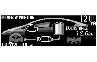
EV Mode
-
Displays the distance the vehicle can travel in EV mode according to the signals from the power management control ECU.
-
Displays the energy flow in the form of an arrow according to the signals from the power management control ECU.
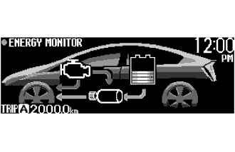
HV Mode
-
Displays the energy flow in the form of an arrow according to the signals from the power management control ECU.
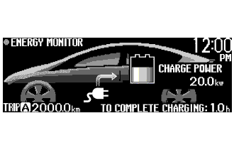
During Plug-in Charging
-
During plug-in charging, by turning the power switch on (IG), the energy monitor displays the charging status and the estimated time to complete the charge according to the signals from the power management control ECU.
Hybrid System Indicator (EV Mode) Display Outline 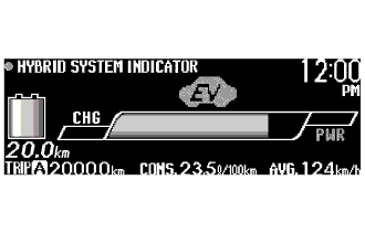
The bar displays real-time information such as the output power and regenerating conditions of the hybrid system in accordance with the accelerator opening degree. 
EV Driving Indicator Light
-
Turns on/off depending on the hybrid system output status during vehicle operation, displaying the EV driving state in which only the motor is running with the engine stopped.
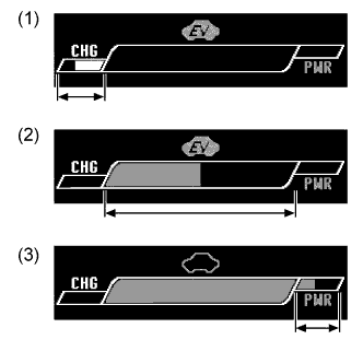
Charge Area: (1)
-
The left-end charge area bar turns white and informs the driver of a state in which energy is being regenerated.
-
The EV driving indicator light turns on.*1
EV Drive Area: (2)
-
The center of the bar turns green and informs the driver of an EV driving state in which only the motor is running with the engine stopped.
-
The EV driving indicator light turns on.*1
Power Area*2: (3)
-
The power area on the upper right bar turns red and informs the driver of a driving state in which the engine is started up.
-
The EV driving indicator light turns off.
*1: EV driving Indicator light may turn off even when the Hybrid System Indicator is in the charge or EV drive area. The power management controls the engine speed in accordance with the vehicle driving conditions.
*2: During EV city mode, the bar is limited to the charge or EV drive area.
Hybrid System Indicator (HV Mode) Display Outline 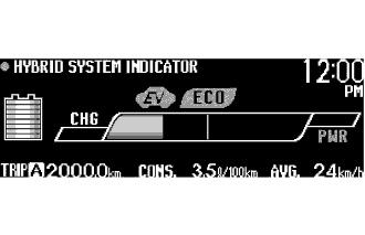
The bar displays real-time information such as the output power and regenerating conditions of the hybrid system in accordance with the accelerator opening degree. 
Eco Driving Indicator Light
-
Receives the signal from the power management control ECU during vehicle operation and turns on/off the indicator depending on the situation, whether Eco-friendly acceleration is being performed or not.
Charge Area: (1)
-
The left-end charge area bar turns white and informs the driver of a state in which energy is being regenerated.
-
Eco driving indicator light turns on.
Hybrid Eco Area: (2)
-
The left half of the bar turns green and informs the driver of an Eco-friendly driving state, in which the vehicle uses less power and the engine is more likely to stop operating.
-
Eco driving indicator light turns on.
Eco Area (3)
-
The right half of the bar turns white and informs the driver of an environmental-friendly driving state.
-
Eco driving indicator light turns on.
Power Area (4)
-
The power area on the upper right bar turns red and informs the driver of a driving state in which power rather than environmental consideration is required.
-
Eco driving indicator light turns off.
Fuel Consumption Record Display Outline 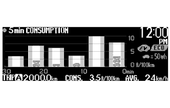
5 min. Consumption Record
-
Displays the history of the average fuel consumption in 5 minute intervals on a bar graph. Displays the average recovered energy amount for 5 minutes using a symbol.
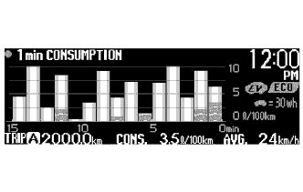
1 min. Consumption Record
-
Displays the history of the average fuel consumption in 1 minute intervals on a bar graph. Displays the average recovered energy amount for 1 minute using a symbol.
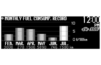
Monthly Fuel Consumption Record
-
Calculates the average monthly fuel consumption and shows it on a bar graph.
-
Monthly average fuel consumption for the current and previous 5 months is displayed.
Plug-in Hybrid Information Display Outline 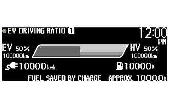
EV Driving Ratio
-
Displays EV and HV mode driving distance ratios for the total driving distance in numeric values and a bar graph.
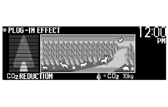
Plug-in Effect
-
The result of the reduction of CO2, which was realized due to repeated plug-in charge operations, is displayed using a battery charge level indicator and an illustration of trees, flowers and animals.
-
-
-
Custom Setting Function for Multi-information Display
-
When the vehicle speed is approximately 8 km/h (5 mph) or less, the display mode for the following 6 items can be used.
Item Customizing Value CALENDAR Adjusts the date. EV / ECO Selects the Eco Driving Indicator Light and EV Driving Indicator Light on/off mode. STEERING SWITCH Selects the touch tracer display on/off mode. CLOCK Selects the 12/24 hour time display mode. LANGUAGE Selects the display language. SCREEN OFF Turns on/off the multi-information display. 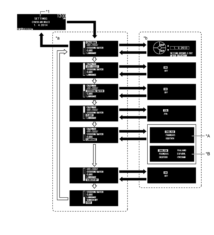
Text in Illustration *A RHD Models for Europe *B LHD Models for Europe *1 Setting Screen - - *a Setting Item Selection Screen *b Setting Selector Screen 
DISP switch is pressed and held. 
DISP switch is pressed briefly.
-
-
Buzzer
-
The table below shows the warning and reminder functions of the buzzer in the combination meter assembly:
Item READY Parking (P) Request Reverse (R) Selected Warning Low HV Battery Voltage Warning Entry and Start System Warning HV Battery Charging Request Immobiliser Certification Reminder Parking Brake Engaged Warning Low Fuel Warning Door Open Driving Warning Seat Belt Warning Shift Reject Warning VSC Operating Warning Multi-information Display Warning Accelerator Depression with Neutral (N) Selected Dynamic Radar Cruise Control Cancellation due to Low Vehicle Speed* Dynamic Radar Cruise Control Warning* Low Fuel Indicator Brake System Warning Hill-start Assist Control Indication *: Models with dynamic radar cruise control system
-
-
Warning Message
-
When a warning is necessary, the warning display interrupts the current display on the multi-information display.
-
The master warning light may illuminate or blink and the buzzer in the combination meter assembly may sound depending on the item in the multi-information display.
Priority Warning Message Master Warning Light Buzzer 1 MAINTENANCE MODE - - CERTIFICATION MODE - - CHECKING CRUISE CONTROL C/D - - CHECKING CRUISE CONTROL BRAKE - - BRAKE! - - 2 RECHARGE INLET DOOR IS OPEN - - 3 AUTO POWER OFF TO CONSERVE BATTERY - - 4 SHIFT TO P POSITION Blinks Sounds SHIFT TO P POSITION WHEN PARKED Blinks Sounds N POSITION Blinks Sounds DEPRESS BRAKE PEDAL WHEN VEHICLE IS AT A STANDSTILL Blinks Sounds TRACTION BATTERY PROTECTION MODE RESTART AFTER SHIFTING TO P POSITION Blinks Sounds TRACTION BATTERY POWER LOW CHARGE WHEN NOT IN N POSITION Blinks Sounds 5 P LOCK MALFUNCTION WHEN PARKING, PARK IN FLAT PLACE AND APPLY PARKING BRAKE SECURELY Illuminates Sounds SHIFT MALFUNCTION. WHEN PARKING, PARK IN FLAT PLACE AND APPLY PARKING BRAKE SECURELY Illuminates Sounds AUX. BATTERY LOW. WHEN PARKING, PARK IN FLAT PLACE AND APPLY PARKING BRAKE SECURELY Illuminates Sounds SHIFT MALFUNCTION. SEE OWNER'S MANUAL Illuminates Sounds CHECK HYBRID SYSTEM STOP THE VEHICLE IN A SAFE PLACE Illuminates Sounds CHECK BRAKE LAMP SYSTEM Illuminates Sounds 6 KEY NOT DETECTED Blinks Sounds 7 SWITCHED TO N. TO SHIFT TO P, STOP CAR AND PRESS P SWITCH. Blinks Sounds CLEAN RADAR SENSOR Illuminates Sounds CRUISE CONTROL NOT AVAILABLE Illuminates Sounds 8 CHECK CRUISE CONTROL SYSTEM Illuminates Sounds CHECK PCS SYSTEM Illuminates Sounds LOW ENGINE OIL PRESSURE Illuminates Sounds 9 TURN POWER OFF Blinks Sounds SHIFT TO P POSITION AND PUSH POWER SWITCH TO TURN OFF Blinks Sounds KEY DETECTED IN VEHICLE Blinks Sounds DEPRESS BRAKE PEDAL, TOUCH POWER SWITCH WITH KEY Blinks Sounds DEPRESS BRAKE PEDAL AND PUSH POWER SWITCH TO START Blinks Sounds SHIFT TO P POSITION WHEN STARTING Blinks Sounds 10 READY INDICATOR OFF PUSH POWER SWITCH OFF AND RECONNECT CHARGE CONNECTOR Illuminates Sounds DISCONNECT CHARGE CONNECTOR BEFORE POWER SWITCH ON Illuminates Sounds SHIFT TO P POSITION WHEN STARTING Blinks Sounds 11 KEY BATTERY LOW Illuminates Sounds HYBRID SYSTEM OVERHEAT Illuminates Sounds 12 PCS NOT CURRENTLY AVAILABLE - - PRESS & HOLD EV CITY SWITCH TO CHANGE TO EV CITY MODE - Sounds EV CITY MODE NOT AVAILABLE BECAUSE HEATER ON - Sounds EV CITY MODE NOT AVAILABLE BECAUSE EXCESSIVE ACCEL - Sounds EV CITY MODE NOT AVAILABLE BECAUSE EXCESSIVE EV CITY SPEED - Sounds EV CITY MODE NOT AVAILABLE BECAUSE LOW BATTERY - Sounds EV CITY MODE NOT AVAILABLE BECAUSE WARMING UP - Sounds EV CITY MODE NOT AVAILABLE BECAUSE BATTERY TEMPERATURE LOW - Sounds EV CITY MODE NOT AVAILABLE - Sounds EV CITY MODE DEACTIVATED BECAUSE HEATER ON - Sounds EV CITY MODE DEACTIVATED BECAUSE EXCESSIVE ACCEL - Sounds EV CITY MODE DEACTIVATED BECAUSE EXCESSIVE EV CITY SPEED - Sounds EV CITY MODE DEACTIVATED BECAUSE LOW BATTERY - Sounds EV CITY MODE DEACTIVATED - Sounds EV CITY MODE DEACTIVATED BECAUSE BATTERY TEMPERATURE LOW - Sounds EV MODE CURRENTLY NOT AVAILABLE - Sounds EV MODE NOT AVAILABLE WARMING UP - Sounds EV MODE NOT AVAILABLE LOW BATTERY - Sounds EV MODE NOT AVAILABLE EXCESSIVE SPEED - Sounds EV MODE NOT AVAILABLE EXCESSIVE ACCEL - Sounds EV MODE CURRENTLY NOT AVAILABLE BECAUSE HEATER ON - Sounds EV MODE DEACTIVATED - Sounds EV MODE DEACTIVATED LOW BATTERY - Sounds EV MODE DEACTIVATED EXCESSIVE SPEED - Sounds EV MODE DEACTIVATED EXCESSIVE ACCEL - Sounds EV MODE CANCELLED BECAUSE HEATER ON - Sounds HAVE TRACTION BATTERY INSPECTED - - VEHICLE START WILL SOON BE DISABLED HAVE TRACTION BATTERY INSPECTED - - VEHICLE START DISABLED UNTIL TRACTION BATTERY INSPECTED - - CHARGE RESULT: CHARGE COMPLETE - - CHARGE RESULT: CHARGE STOPPED DUE TO SYSTEM MALFUNCTION - - CHARGE RESULT: CHARGE COMPLETE (RESTRICTED DUE TO BATT. TEMP.) - - CHARGE RESULT: CHARGE STOPPED TO PROTECT BATTERY DUE TO HI ELEC. CONSUMP. - - CHARGE RESULT: CHARGE STOPPED DUE TO CHARGE CONNECTOR OPERATION - - CHARGE RESULT: CHARGE STOPPED DUE TO OUTAGE OR PLUG REMOVE - - CHARGE RESULT: CHARGE STOPPED DUE TO INSUFF. POWER SUPPLY - - CHARGE RESULT: CHARGE STOPPED DUE TO CHARGE CABLE OR OTHER - - THEFT SENSOR OFF - - THEFT SENSOR ON - - 13 CHECK HEADLIGHT SYSTEM Blinks - * SET TIME START - - SET TIME FINISH - - Tech Tips
When multiple warning conditions occur at the same time, the highest priority warning message is displayed first. The next high priority warning message can be displayed by pressing the DISP switch briefly.
*: Higher priority than other messages
-
-
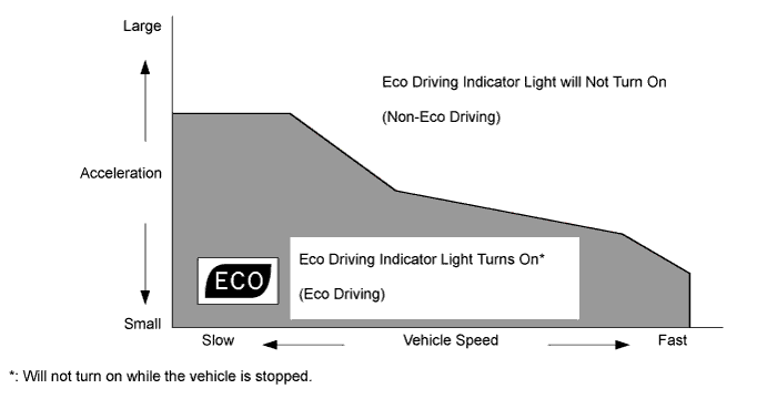
Eco Driving Indicator Light
-
When the power management control ECU determines, by using information such as vehicle speed, vehicle power, shift position and drive mode, that the driving is Eco, it turns on Eco driving indicator light. The operating diagram of Eco driving indicator light function is as follows:
-
-
Light Control Rheostat
-
The brightness of the instrument panel can be adjusted when the taillights are turned on.
-
The nighttime brightness level of the combination meter can be adjusted between 2.08% and 16.5% of the daytime brightness level of 100%, by using a dial-type switch. The indicator lights on the combination meter can be turned off by further decreasing the brightness level.
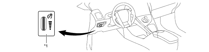
Text in Illustration *1 Light Control Rheostat - -
-
-
-
CONSTRUCTION
-
Combination Meter
-
A reflective display method is used to display the speed meter, fuel gauge, instantaneous fuel consumption and shift position. Using the Vacuum Fluorescent Display (VFD), the light emitted by the vacuum fluorescent display panel is reflected in the reflective glass, allowing a virtual image to be visible to the driver's eyes.
-
Light emitted in the display area is transmitted through the reflective glass, allowing the warning lights, indicator lights and information on the multi-information display to be visible to the driver's eyes.
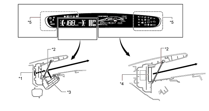
Text in Illustration *1 Virtual Image *2 Reflective Glass *3 Vacuum Fluorescent Display (VFD) *4 VFD or LED Indicator Display *5 Light Emitting Diode (LED) Indicator Display - -
-
-
Touch Tracer Display
-
A touch sensor is provided on frequently used switches such as the DISP switch, TRIP switch, audio and air conditioning switches. The touch tracer display is displayed when any of the switches is touched by the driver's finger, and the switch is activated when pressed.
Steering Pad Switch Audio System Volume Switch (+) Volume Switch (-) Mode Switch Seek Switch (Up) Seek Switch (Down) Multi-information Display TRIP Switch DISP Switch Air Conditioning System Air Inlet Control Switch Temp Switch (Up) Temp Switch (Down) 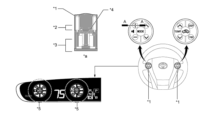
Text in Illustration *1 Steering Pad Switch *2 Touch Switch Area *3 Function Switch Area *4 Touch Sensor *5 Touch Tracer Display - - *a A-A Cross Section - -
-
-
Headup Display
-
The Headup display projects the image from the dot Vacuum Fluorescent Display (VFD), built into the Headup display unit (combination meter mirror ECU), in a position approximately 2 m (6.6 ft) forward of the driver using a concave mirror and the windshield, in order to support the driver with various information.
-
By changing the angle of the concave mirror, the position of the image displayed can be adjusted.
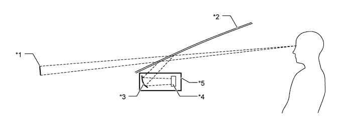
Text in Illustration *1 Headup Display image *2 Windshield Glass *3 Concave mirror *4 Dot VFD *5 Headup Display Unit (Combination Meter Mirror ECU) - -
-
-
Windshield Glass for Headup Display
-
Windshield glass without a combiner treatment is used for the Headup display.
-
This glass has a wedge-shaped inner film. This film, with its varying thickness, is located between the outer and inner layers of glass.
-
The light that strikes the glass is reflected by the inner surface of the inner glass, and also by the inner side of the outer surface of outer layer of glass. With a conventional windshield, the light reflected from these 2 surfaces diverges due to the thickness of the glass, resulting in a double image.
-
The film's wedge shape is used to eliminate the reflection angle difference between the outer glass and inner glass. This recombines the reflected light and eliminates the double image.
-
Thus, the reflected light from the Headup display unit is seen by the driver as a single display image.
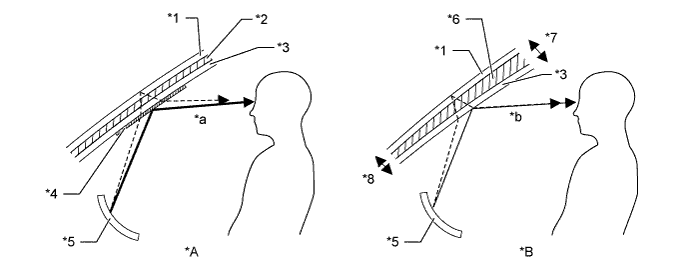
Text in Illustration *A Windshield Glass with Normal Film *B Windshield Glass with Wedge-shaped Film *1 Outer Glass *2 Uniform Thickness Film *3 Inner Glass *4 Combiner *5 Concave Mirror *6 Wedge-shaped Film *7 Thick *8 Thin *a The combiner makes the light reflected by the inner glass brighter, however, a double image is caused by a divergence of the reflected light. *b Reflected light is recombined and a double image is prevented.
-
-
-
OPERATION
-
Switching the Multi-information Display
-
The multi-information display changes in the order below each time the DISP switch is pressed.
-
The items displayed on the energy monitor and the hybrid system indicator automatically change depending on the EV and HV modes in the hybrid system.
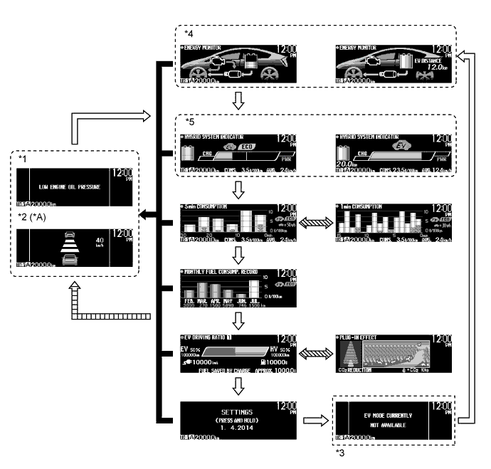
Text in Illustration *A Models with Dynamic Radar Cruise Control System / Pre-crash Safety System - - *1 Warning Message *2 Dynamic Radar Cruise Control System / Pre-crash Safety System Display *3 When warning conditions are not solved. *4 Energy Monitor *5 Hybrid System Indicator - - When warning message request signals are received. DISP switch is pressed briefly. 
DISP switch is pressed and held. 
Automatically switching in accordance with the hybrid system.
-
-
Charging Timer Setting
-
The charge timer setting screen is provided on the multi-information display, enabling the starting time and finishing time of plug-in charge to be set.
-
By operating the charging timer switch located on the satellite switch set, the multi-information display enters charge display mode.
-
The time of the charging timer function can be set using the clock adjust switches on the satellite switch set.
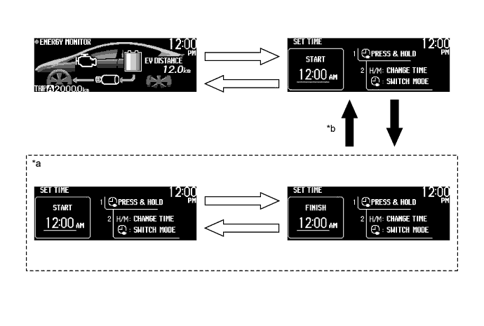
Text in Illustration *a Charging Timer Setting Mode
-
The clock display starts flashing when time setting mode is entered.
-
While the clock is flashing, operating the clock adjust switches sets the starting time or finishing time.
*b Charging timer setting is complete.
-
When the setting is complete, the charge timer indicator light in the combination meter assembly illuminates.
Charging timer switch is pressed briefly Charging timer switch is pressed and held -
-
-
Headup Display Switch (Satellite Switch Set)
-
The headup display changes in the order below by pressing the headup display switch (satellite switch set).
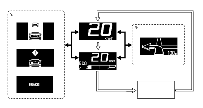
Text in Illustration *a Dynamic Radar Cruise Control System, Pre-crash Safety System Warning Indicators are displayed. *b Turn-by-turn Navigation Display Headup Display Main Switch is Pressed Briefly. When dynamic radar cruise control system, pre-crash safety system and turn-by-turn navigation display signals are received.
-
-