ENTRY AND START SYSTEM DETAILS
-
FUNCTION OF MAIN COMPONENTS
-
Start Function
-
The main components in the start function have the following functions:
Component Function
-
Power Switch
-
Transponder Key Amplifier
-
Used to turn the power source on and start the hybrid control system.
-
An indicator light is built into the power switch so that the driver can check whether the hybrid control system can start.
-
An immobiliser amplifier is also built into the power switch to start the hybrid control system when the key does not operate properly due to a weak key battery or radio interference.
Electrical Key Transmitter Sub-assembly
-
Outputs the key ID and vehicle ID codes upon receiving radio waves from the antennas.
-
Outputs the key ID and vehicle ID codes to the certification ECU (smart key ECU assembly)*1 or ID code box (immobiliser code ECU)*2 upon receiving radio waves from the immobiliser amplifier built into the power switch.
Indoor Electrical Key Antennas Emits radio waves into the cabin to determine whether the key is in the interior actuation area. Door Control Receiver Receives the key ID and vehicle ID codes from the key and outputs them to the certification ECU (smart key ECU assembly). Power Management Control ECU
-
Turns the power source to off, on (ACC), on (IG) or READY in accordance with the shift state and the state of the stop light switch.
-
Controls the power switch indicator light.
-
Activates the IG and ACC relays.
-
Starts the hybrid control system.
-
Receives the engine immobiliser set/unset command signal from the certification ECU (smart key ECU assembly)*1 or ID code box (immobiliser code ECU)*2, and sets or unsets the engine immobiliser.
Certification ECU (Smart Key ECU Assembly)
-
Verifies the codes output from the key.
-
Controls the electrical key antennas.
-
Generates the actuation area of the start function.
-
Registers the ID verification code.
ID Code Box (Immobiliser Code ECU)*2
-
Receives the engine immobiliser set/unset command signal from the certification ECU (smart key ECU assembly) and outputs it to the power management control ECU.
-
Registers the ID verification code.
Transmission Control ECU Assembly
-
Outputs a signal indicating whether park (P) is selected or not to the power management control ECU.
-
Registers the ID verification code.
Stop Light Switch Assembly Detects that the brake pedal is depressed and outputs the signal to the power management control ECU. P Position Switch (Transmission Shift Main Switch) Outputs the P position switch signal to the power management control ECU. Shift Lever Position Sensor (Shift Lock Control Unit Assembly) Outputs the shift position demand signal to the power management control ECU.
-
Combination Meter Assembly
-
Multi-information Display
-
Buzzer
Sounds the buzzer and displays information via the multi-information display according to the activation signal from the certification ECU (smart key ECU assembly). Wireless Door Lock Buzzer Sounds to inform the driver of malfunctions in the start function. *1: Models for Australia
*2: Models for Europe
-
-
-
Entry Function
-
The main components in the entry function have the following functions:
Component Function Electrical Key Transmitter Sub-assembly
-
Outputs the key ID and vehicle ID codes upon receiving radio waves from the electrical key antennas.
-
Transmits radio waves of the key switch operation signals.
Main Body ECU (Multiplex Network Body ECU)
-
Receives the request signal from the certification ECU (smart key ECU assembly) and actuates the door lock motors to unlock or lock all the doors and the back door.
-
Inputs the condition of each door and the back door to the certification ECU (smart key ECU assembly).
Certification ECU (Smart Key ECU Assembly)
-
Verifies the codes output from the key.
-
Controls the electrical key antennas, unlock sensor and lock sensor.
-
Outputs the door lock/unlock command to the main body ECU (multiplex network body ECU).
-
Generates the actuation area of the entry function.
-
Registers the ID verification code.
Front Door Outside Handle Door Electrical Key Antenna Emits the radio waves generated by the certification ECU (smart key ECU assembly). Unlock Sensor Detects the entry unlock operation. Lock Sensor Detects the entry lock operation. Outside Electrical Key Antenna* Receives the request signal from the certification ECU (smart key ECU assembly) and generates an actuation area around the back door. Indoor Electrical Key Antennas Emits radio waves into the cabin to determine whether the key is in the interior actuation area. Door Control Receiver Receives the key ID and vehicle ID codes from the key and outputs them to the certification ECU (smart key ECU assembly). Back Door Opener Switch* Outputs the back door opener switch on/off signal to the certification ECU (smart key ECU assembly). Back Door Lock Switch* Outputs the back door lock switch on/off signal to the certification ECU (smart key ECU assembly). Door Lock Assembly
-
Locks or unlocks the doors by rotating the built-in door lock motor in the forward or reverse direction.
-
By using the built-in door lock position switch, detects whether the door is locked or unlocked and outputs it to the main body ECU (multiplex network body ECU).
Back Door Lock Assembly
-
Releases the latch of the back door lock assembly by activating the built-in back door lock motor.
-
By using the built-in back door courtesy switch, detects whether the back door is open or closed and outputs it to the main body ECU (multiplex network body ECU).
Door Courtesy Light Switch Detects whether the front door is open or closed and outputs it to the main body ECU (multiplex network body ECU). Turn Signal Flasher Assembly Flashes the hazard warning lights as an answer back according to the signal from the main body ECU (multiplex network body ECU).
-
Combination Meter Assembly
-
Multi-information Display
-
Buzzer
-
Sounds the buzzer and displays the multi-information display in the combination meter according to the activation signal from the certification ECU (smart key ECU assembly).
-
Outputs the vehicle speed signal to the main body ECU (multiplex network body ECU).
Wireless Door Lock Buzzer
-
Sounds as an answer back for entry lock or unlock to inform the driver.
-
Sounds to inform the driver of malfunctions in the entry function.
-
*: Models with entry function for driver door, front passenger door, and back door.
-
-
-
-
OPERATING CONDITION
-
Entry and Start System Actuation Area
-
The special functions of the entry and start system only work when the key is in the actuation area formed by the antennas.
-
The indoor electrical key antennas form the interior actuation area.
-
The door electrical key antenna RH and LH and the electrical key antenna (back door) form the exterior actuation areas.
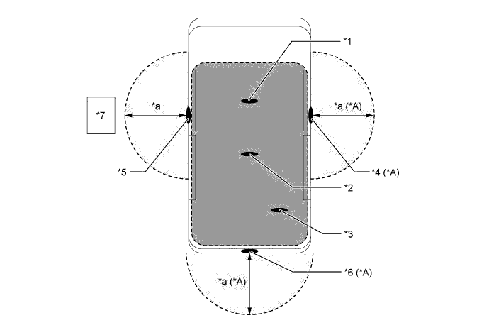
Text in Illustration *A Models with Entry Function for Driver Door, Front Passenger Door and Back Door - - *1 Indoor Electrical Key Antenna Assembly No. 1 (Front) *2 Indoor Electrical Key Antenna Assembly No. 3 (Center) *3 Indoor Electrical Key Antenna Assembly No. 2 (Rear) *4 Door Electrical Key Antenna RH *5 Door Electrical Key Antenna LH *6 Electrical Key Antenna (Back Door) *7 Electrical Key Transmitter Sub-assembly - - *a Approximately 0.7 to 1.0 m (2.3 to 3.3 ft.) - - 
Interior Actuation Area 
Exterior Actuation Area Each Actuation Area Actuation Area Details Interior The interior actuation area formed by the indoor electrical key antenna assemblies (front, center, rear) is formed when the driver door is opened or closed, when the power switch is pressed, when a warning is activated, when the lock sensor is on, or when the brake pedal is depressed. Exterior The exterior actuation areas formed by the door electrical key antennas (LH, RH) and outside electrical key antenna (back door) is approximately 0.7 to 1.0 m (2.3 to 3.3 ft.) from the outside handle of the front doors, or the center of the rear bumper. Front Doors The exterior actuation areas formed by the door electrical key antennas (LH, RH) is formed by transmitting a request signal approximately every 0.25 seconds while the power switch is off and each door is locked. In this way it detects the proximity of a key. When locking the door using the lock sensor on the outside handle, the actuation area is formed when the lock sensor is touched. Back Door
-
The exterior actuation area formed by the outside electrical key antenna (back door) is formed when the back door opener switch is on.
-
The exterior actuation area formed by the outside electrical key antenna (back door) is formed when the back door lock switch is on.
-
-
-
-
SYSTEM CONTROL
-
Start Function
-
The start function consists of the following functions:
Function Outline Start Function The start function is operated by simply pressing the power switch while carrying the key. When the power switch is pressed, the power management control ECU turns the ACC relay and IG relay on and off to switch the power source pattern. The power source pattern changes depending on if the brake pedal is depressed and the selected shift state. Start Function Immobiliser The immobiliser function compares the ID code that is registered in the certification ECU (smart key ECU assembly)*1 or ID code box (immobiliser code ECU)*2 with the ID code of the transponder chip that is embedded in the key. *1: Models for Australia
*2: Models for Europe
-
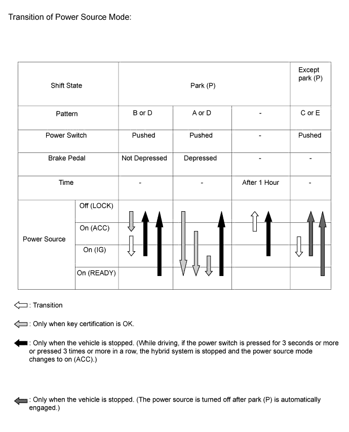
The start function has different power source patterns to suit the brake pedal state and the selected shift state.
Pattern Brake Pedal Shift State Power Source Pattern A Depressed Park (P)
-
When the power switch is pushed once.
-
Off, On (ACC) or On (IG) → READY* (The hybrid control system is started)
B Not Depressed Park (P)
-
Each time the power switch is pushed.
-
Off → On (ACC) → On (IG) → Off
C - Except park (P)
-
Each time the power switch is pushed.
-
On (ACC) → On (IG)
D - Park (P)
-
When the power switch is pushed in the READY condition.
-
READY → Off
E - Except park (P)
-
When the power switch is pushed in the on (IG) or READY condition.
-
On (IG) or READY → Off
Tech Tips
*: While the hybrid control system is being charged using the plug-in charger, the power source will change to on (IG), not to READY.
Note
-
Normally, the operation of the power switch is disabled while the vehicle is being driven. However, in an emergency, pressing and holding the power switch for approximately 3 seconds or more or pressing the power switch 3 times or more in a row, enables the driver to stop the hybrid control system while the vehicle is in motion.
-
If no signals are transmitted to the power management control ECU due to malfunctions in the stop light switch, P position switch or transmission control ECU, the hybrid control system may not start when the power switch is pressed with the brake pedal depressed. In such cases, performing the following procedure may enable the hybrid control system to start: 1) press the power switch to turn the power source from off to on (ACC), and 2) press the power switch again and hold it for 15 seconds or more.
-
The above 2 operations must be applied only in emergency situations. Under normal conditions, the hybrid control system must not be stopped by pressing the power switch while driving. Also, it should not be started without depressing the brake pedal or when a shift state other than park (P) has been selected.
-
-
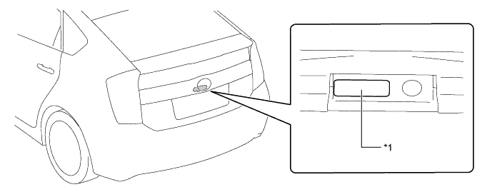
Transition of the power source when the key does not operate properly due to a depleted battery or radio interference.
-
Unlock the door with the built-in mechanical key and get in the vehicle while carrying the key.
-
Bring the key ornament face into contact with the front face of the power switch with the brake pedal depressed.
-
Release the brake pedal within approximately 10 seconds after the buzzer in the combination meter sounds, and press the power switch.
-
Each time the power switch is pressed, the power source is turned from off to on (ACC), on (ACC) to on (IG), and then on (IG) to off.
-
-
Hybrid control system start-up when the key does not operate properly due to a depleted battery or radio interference.
-
Unlock the door with the built-in mechanical key and get in the vehicle while carrying the key.
-
Bring the key ornament face into contact with the front face of the power switch with the brake pedal depressed and park (P) selected.
-
Press the power switch with the brake pedal depressed within approximately 10 seconds after the buzzer in the combination meter sounds and the power switch indicator light turns green.
-
The hybrid control system starts when the power switch is pressed.
-
-
-
-
FUNCTION
-
Entry Function
-
The entry function consists of the following functions:
Function Outline Wireless Door Lock Control This function is a convenient system for locking and unlocking all the doors from a distance. The operation of this function is the same as that of the wireless door lock control system. Entry Illumination When a key enters the exterior actuation area formed by the door electrical key antennas (LH, RH) or the electrical key antenna (back door) the interior lights illuminate. Entry Unlock When a key is located in an exterior actuation area formed by a door electrical key antenna (LH, RH) or the electrical key antenna (back door) and the power switch is off, all doors can be unlocked by simply touching the unlock sensor. Entry Lock When a key is located in an exterior actuation area formed by a door electrical key antenna (LH, RH) or the electrical key antenna (back door) and the power switch is off, all doors can be locked by simply touching the lock sensor or pressing the back door lock switch. Back Door Open When a key is in the exterior actuation area of the electrical key antenna (back door), the back door opens manually by simply pressing the back door opener switch. Prevention of Key Confinement The key confinement prevention function prevents the key from being locked inside the vehicle. This function operates in 2 different situations: wireless door lock control function and entry function. Warning This function causes the certification ECU (smart key ECU assembly) to sound the buzzer in the combination meter and the wireless door lock buzzer, and indicates a warning on the multi-information display in order to alert the driver. Battery Saving If the key remains within the exterior actuation area formed by a door electrical key antenna (LH, RH) or the electrical key antenna (back door), the system maintains periodic communication with key. Therefore, if the vehicle remains parked in that state for a long time, the key battery and the vehicle battery could be drained. Entry Unlock Mode Switching
-
Allows switching between 2 modes that can be operated with the entry unlock function.
-
Driver Door Mode
-
All Doors Mode
Key Cancel
-
The following key functions can be cancelled by following certain procedures.
-
Entry Unlock/Lock
-
Back Door Open
-
Prevention of Key Confinement
-
Warning
Key Code Registration A total of 7 keys can be registered. Enables the registering (writing and storing) of transmitter recognition codes in the EEPROM that is contained in the certification ECU (smart key ECU assembly). -
-
-
Wireless Door Lock Control Function
-
The wireless door lock control function has the following functions:
Function Outline All Doors Lock Pressing the lock button of the key locks the doors. All Doors Unlock Pressing the unlock button of the key once unlocks all doors. Answer Back
-
When the doors are being locked or unlocked through the operation of the key, the hazard warning lights blink once during locking and twice during unlocking.*1
-
When the doors are being locked or unlocked through the operation of the key, the wireless door lock buzzer sounds and the hazard warning lights blink once during locking and twice during unlocking.*2
-
Also, the answer back function operates when the doors are locked by the auto relock function.
Panic Alarm*2
-
Keeping the panic button of the key pressed longer than approximately 0.8 seconds causes the following to activate as an alarm.
-
Sounds the horn.
-
Flashes the hazard warning lights, headlights and taillights.
-
Illuminates the interior lights (If the switch is in the door position).
Automatic Relock If none of the doors are opened within approximately 30 seconds after they are unlocked using the wireless door lock remote control, all the doors will be locked again automatically. Security Sends a door lock/unlock operation request signal as a rolling code. Door Ajar Warning If any door is open or ajar, pressing the lock button of the key will cause the wireless door lock buzzer to sound for approximately 5 seconds as a warning. *1: Models for Europe
*2: Models for Australia
Tech Tips
These function settings can be changed using the customized body electronics system. For details, refer to the Repair Manual.
-
-
-
Entry Unlock Function
-
While the key is in an exterior actuation area, if the front door outside handle is held (the back side of the handle is touched), the door unlock sensor built into the handle will detect it and the doors will be unlocked.
-
When the doors are unlocked, the hazard warning lights flash twice as an answer back.
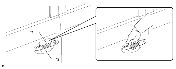
Text in Illustration *1 Front Door Outside Handle *2 Unlock Sensor
-
-
Entry Lock Function
-
If the lock sensor of a door outside handle is touched with the key in an exterior actuation area and all doors closed, the doors will be locked.
-
If the back door lock switch is pressed with the key in the back door exterior actuation area and all doors closed, the doors will be locked.
-
When the doors are locked, the hazard warning lights flash once as an answer back.
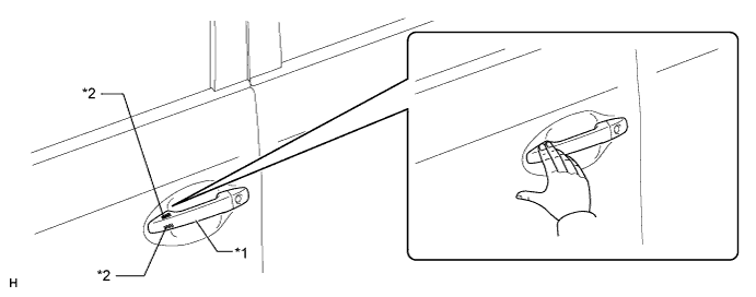
Text in Illustration *1 Front Door Outside Handle *2 Lock Sensor 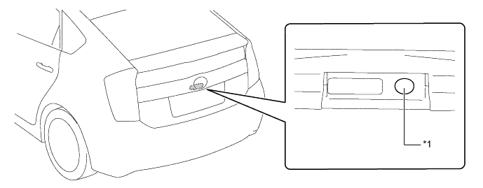
Text in Illustration *1 Back Door Lock Switch - -
-
-
Back Door Open
-
If the back door opener switch is pressed with the key in the back door exterior actuation area, the back door will open.
Text in Illustration *1 Back Door Opener Switch - -
-
-
Warning
-
When any of the situations below occur, the entry and start system causes the certification ECU (smart key ECU assembly) to sound a buzzer in the combination meter assembly and the wireless door lock buzzer, illuminate the power switch illumination and display a message on the multi-information display in order to alert the driver.
Situation Condition A The hybrid control system is left running and a shift state other than park (P) is selected when the driver gets out of the vehicle. B The hybrid control system is left running with park (P) is selected when the driver gets out of the vehicle. C A door is ajar and a lock sensor is touched. D The hybrid control system is left running when a passenger gets out of the vehicle while holding the key. E The key is not within an actuation area. F The key is left in the vehicle interior and a lock sensor is touched. G The key battery is weak. H A hybrid control system start method is displayed, pattern 1. I A hybrid control system start method is displayed, pattern 2. J A hybrid control system start method is displayed, pattern 3. K The power management control ECU is malfunctioning. L Automatic power off operation occurs. M Engine immobiliser system certification completion occurs. N The vehicle is driving with the key not in the vehicle interior. -
There are 2 patterns for situation A.
-
Pattern 1: When the hybrid control system is left running and a shift state other than park (P) is selected, the driver opens the door and attempts to get out of the vehicle. In this situation, the following control is performed:
Possible Effects without Warning Sudden vehicle start, Vehicle theft, Vehicle roll-away Warning Active Condition
-
The warning is activated when all of the following conditions are met:
-
Power source is in a mode other than off.
-
A shift state other than park (P) is selected.
-
Vehicle speed is 0 km/h (0 mph).
-
Driver door is opened.
Waning Method Combination Meter Assembly Buzzer Sounds continuously Wireless Door Lock Buzzer - Power Switch Illumination - Multi-information Display Displays "SHIFT TO P POSITION". Warning Stop Condition
-
The warning is stopped when one of the following conditions is met:
-
Power source is off.
-
Park (P) is selected.
-
Vehicle speed is 5 km/h (3 mph) or more.
-
Driver door is closed.
-
-
Pattern 2: Under the conditions of pattern 1, the driver closes the door and attempts to leave the vehicle while carrying the key. In this situation, the following control is performed:
Possible Effects without Warning Sudden vehicle start, Vehicle theft, Vehicle roll-away Warning Active Condition
-
The warning is activated when all of the following conditions are met:
-
Power source is in a mode other than off.
-
A shift state other than park (P) is selected.
-
Vehicle speed is 0 km/h (0 mph).
-
Driver door is opened → closed.
-
Key is not in the vehicle interior.
Waning Method Combination Meter Assembly Buzzer Sounds continuously Wireless Door Lock Buzzer Sounds continuously Power Switch Illumination - Multi-information Display Alternately displays "SHIFT TO P POSITION" and "KEY NOT DETECTED". Warning Stop Condition
-
The warning is stopped when one of the following conditions is met:
-
Power source is off.
-
Vehicle speed is 5 km/h (3 mph) or more ("KEY NOT DETECTED" indicator will remain on).
-
Park (P) is selected ("KEY NOT DETECTED" indicator will remain on).
-
Key is in the vehicle interior ("SHIFT TO P POSITION " indicator will remain on).
-
-
There are 2 patterns for situation B.
-
Pattern 1: When the hybrid control system is left running with park (P) selected, the driver closes the driver's door and attempts to leave the vehicle while holding the key. In this situation, the following control is performed:
Possible Effects without Warning Vehicle theft Warning Active Condition
-
The warning is activated when all of the following conditions are met:
-
Power source is in a mode other than off.
-
Park (P) is selected.
-
Vehicle speed is 0 km/h (0 mph).
-
Driver door is opened → closed.
-
Key is not in the vehicle interior.
Waning Method Combination Meter Assembly Buzzer Sounds once Wireless Door Lock Buzzer Sounds 3 times Power Switch Illumination - Multi-information Display Displays "KEY NOT DETECTED". Warning Stop Condition
-
The warning is stopped when one of the following conditions is met:
-
Power source is off.
-
Key is in the vehicle interior.
-
-
Pattern 2: Under the conditions of pattern 1, the driver touches the lock sensor. In this situation, the following control is performed:
Possible Effects without Warning Vehicle theft Warning Active Condition
-
The warning is activated when all of the following conditions are met:
-
Power source is in a mode other than off.
-
Park (P) is selected.
-
Vehicle speed is 0 km/h (0 mph).
-
All doors are closed.
-
Key is not in the vehicle interior (within one of the actuation areas).
-
Lock sensor is on.
-
Key is in the exterior actuation area.
Waning Method Combination Meter Assembly Buzzer Sounds once Wireless Door Lock Buzzer Sounds for approximately 5 seconds Power Switch Illumination - Multi-information Display Alternately displays "TURN POWER OFF" and "KEY NOT DETECTED". Warning Stop Condition
-
The warning is stopped when one of the following conditions is met:
-
Power source is off.
-
Key is in the vehicle interior ("TURN POWER OFF" indicator will remain on).
-
A shift state other than park (P) is selected ("KEY NOT DETECTED" indicator will remain on).
-
Any door is opened (stops only the wireless door lock buzzer).
-
-
In the situation C (a door is ajar and lock sensor is touched) the following control is performed.
Possible Effects without Warning Vehicle theft Warning Active Condition
-
The warning is activated when all of the following conditions are met:
-
Power source is off.
-
Lock sensor is on.
-
Any door is opened.
Waning Method Combination Meter Assembly Buzzer - Wireless Door Lock Buzzer Sounds for approximately 5 seconds Power Switch Illumination - Multi-information Display - Warning Stop Condition
-
The warning is stopped when one of the following conditions is met:
-
Power source is in a mode other than off.
-
All doors are closed.
-
All doors are locked via wireless door lock function.
-
All doors are unlocked via entry unlock.
-
-
In the situation D (the hybrid control system is left running when a passenger gets out of the vehicle while holding the key) the following control is performed.
Possible Effects without Warning Hybrid control system cannot be restarted Warning Active Condition
-
The warning is activated when all of the following conditions are met:
-
Power source is in a mode other than off.
-
Door except driver door is opened → closed.
-
Vehicle speed is 0 km/h (0 mph).
-
Key is not in the vehicle interior.
Waning Method Combination Meter Assembly Buzzer Sounds once Wireless Door Lock Buzzer Sounds 3 times Power Switch Illumination - Multi-information Display Displays "KEY NOT DETECTED". Warning Stop Condition
-
The warning is stopped when one of the following conditions is met:
-
Power source is off.
-
Key is in the vehicle interior.
-
-
In the situation E (the key is not within the actuation areas) the following control is performed.
Possible Effects without Warning Confuses the user Warning Active Condition
-
The warning is activated when all of the following conditions are met:
-
Key is not in the vehicle interior.
-
Power switch is pushed.
Waning Method Combination Meter Assembly Buzzer Sounds once Wireless Door Lock Buzzer - Power Switch Illumination - Multi-information Display Displays " KEY NOT DETECTED " for approximately 15 seconds. Warning Stop Condition
-
The warning is stopped when one of the following conditions is met:
-
Key is in the vehicle interior.
-
Power source is off.
-
-
In the situation F (the key is left in the vehicle interior and a lock sensor is touched) the following control is performed.
Possible Effects without Warning Vehicle theft Warning Active Condition
-
The warning is activated when all of the following conditions are met:
-
Power source is off.
-
All doors are closed.
-
Key is in the vehicle interior.
-
Lock sensor is on.
-
Any door is unlocked.
Waning Method Combination Meter Assembly Buzzer - Wireless Door Lock Buzzer Sounds for approximately 5 seconds Power Switch Illumination - Multi-information Display Displays "KEY DETECTED IN VEHICLE" for approximately 60 seconds. Warning Stop Condition
-
The warning is stopped when one of the following conditions is met:
-
Power source is in a mode other than off.
-
Any door is opened (stops only the wireless door lock buzzer).
-
Lock operation is detected.
-
-
In the situation G (the key battery is weak) the following control is performed.
Possible Effects without Warning Entry and start system does not function Warning Active Condition
-
The warning is activated when all of the following conditions are met:
-
Power source switches to off after being left in on (IG) for over 20 minutes.
-
Key battery voltage is low.
Waning Method Combination Meter Assembly Buzzer Sounds once Wireless Door Lock Buzzer - Power Switch Illumination - Multi-information Display Displays "KEY BATTERY LOW" for approximately 15 seconds. Warning Stop Condition The key battery is replaced with a new one. -
-
In the situation H (a hybrid control system start method is displayed, pattern 1) the following control is performed.
Possible Effects without Warning Usability function Warning Active Condition
-
The warning is activated when all of the following conditions are met:
-
Engine immobiliser is activated.
-
Key is not in the vehicle interior.
-
Key code verification error occurs twice when the power switch is pushed or doors are unlocked using the mechanical key.
-
Power switch is pushed.
Waning Method Combination Meter Assembly Buzzer Sounds once Wireless Door Lock Buzzer - Power Switch Illumination - Multi-information Display Displays "DEPRESS BRAKE PEDAL, TOUCH POWER SWITCH WITH KEY" for approximately 15 seconds. Warning Stop Condition
-
The warning is stopped when the following condition is met:
-
Key is in the vehicle interior.
-
-
In the situation I (a hybrid control system start method is displayed, pattern 2) the following control is performed.
Possible Effects without Warning Usability function Warning Active Condition
-
The warning is activated when all of the following conditions are met:
-
Power source is off.
-
Driver door is closed → opened.
-
Power source is turned from off to on (ACC) more than twice while brake pedal is not being depressed.
Waning Method Combination Meter Assembly Buzzer Sounds once Wireless Door Lock Buzzer - Power Switch Illumination - Multi-information Display Displays "DEPRESS BRAKE PEDAL AND PUSH POWER SWITCH TO START". Warning Stop Condition
-
The warning is stopped when one of the following conditions is met:
-
Power source is off.
-
Power source is on (IG).
-
-
In the situation J (a hybrid control system start method is displayed, pattern 3) the following control is performed.
Possible Effects without Warning Usability function Warning Active Condition
-
The warning is activated when all of the following conditions are met:
-
Hybrid control system not activated.
-
Vehicle speed is 0 km/h (0 mph).
-
A shift state other than park (P) is selected.
-
More than 0.5 seconds have elapsed since power source is turned on (IG).
Waning Method Combination Meter Assembly Buzzer - Wireless Door Lock Buzzer - Power Switch Illumination - Multi-information Display Displays "SHIFT TO P POSITION WHEN STARTING". Warning Stop Condition
-
The warning is stopped when one of the following conditions is met:
-
Power source is in a mode other than off.
-
Hybrid control system activated.
-
Vehicle speed is above 0 km/h (0 mph).
-
Park (P) is selected.
-
-
In the situation K (the power management control ECU is malfunctioning) the following control is performed.
Possible Effects without Warning Malfunction detection Warning Active Condition A malfunction of the power management control ECU is detected. Waning Method Combination Meter Assembly Buzzer - Wireless Door Lock Buzzer - Power Switch Illumination The amber indicator blinks at 2 second intervals for 15 seconds. Multi-information Display - Warning Stop Condition The power management control ECU returns to normal or is repaired. -
In the situation L (automatic power off operation occurs) the following control is performed.
Possible Effects without Warning Battery saving function Warning Active Condition
-
The warning is activated when all of the following conditions are met:
-
Park (P) is selected.
-
Vehicle is stationary when power source is on (ACC) or on (IG).
-
Power source was off by automatic power source off function.
Waning Method Combination Meter Assembly Buzzer - Wireless Door Lock Buzzer - Power Switch Illumination - Multi-information Display Displays "AUTO POWER OFF TO CONSERVE BATTERY" for approximately 10 seconds. Warning Stop Condition Power source is in a mode other than off. -
-
In the situation M (engine immobiliser system certification completion occurs) the following control is performed.
Possible Effects without Warning Usability function Warning Active Condition When the key is held close to the power switch and the transponder certification has completed. Waning Method Combination Meter Assembly Buzzer Sounds once Wireless Door Lock Buzzer - Power Switch Illumination - Multi-information Display Displays "DEPRESS BRAKE PEDAL AND PUSH POWER SWITCH TO START" for approximately 10 seconds. Warning Stop Condition
-
The warning is stopped when one of the following conditions is met:
-
Key is in the vehicle interior.
-
Power source is READY.
-
-
In the situation N (the vehicle is running with the key not in the vehicle interior) the following control is performed.
Possible Effects without Warning Hybrid control system cannot be restarted. Warning Active Condition When vehicle speed is detected for the first time after the key is removed from the vehicle, the warning is activated. Waning Method Combination Meter Assembly Buzzer Sounds once Wireless Door Lock Buzzer - Power Switch Illumination - Multi-information Display Displays "KEY NOT DETECTED". Warning Stop Condition
-
The warning is stopped when one of the following conditions is met:
-
Power source is off.
-
Key is in the vehicle interior.
-
-
-
Battery Saving Function
-
Battery saving preserves the vehicle and key batteries. It is activated when the vehicle remains parked for a long time and when the key is left inside the exterior actuation area.
Condition Control Reinstatement Condition When the vehicle remains parked for a long time.
-
Control 1:
No response from electrical key transmitter sub-assembly for more than 5 days
-
- Door electrical key antennas and electrical key antenna stop emitting signals for creating the actuation area.
When the power switch is turned on (IG), the control is canceled and the system is returned to normal.
-
Control 2:
No response from electrical key transmitter sub-assembly for more than 14 days
-
- Door electrical key antennas and electrical key antenna stop emitting signals for creating the actuation area.
-
- Front passenger door lock sensor and unlock sensor are disabled.
-
When the power switch is turned on (IG), the control is canceled and the system is returned to normal.
-
When one of the following conditions is met, the control is returned to control 1:
-
- The doors are locked or unlocked using wireless remote control.
-
- The doors are locked or unlocked by touching the lock/unlock sensor on the driver door.
-
- A door is locked or unlocked using the mechanical key.
-
- Door is opened → closed.
When the key is left within the exterior actuation area.
-
This state continues longer than 10 minutes
-
- Outside electrical key antenna that is detecting the electrical key transmitter sub-assembly stops emitting signals for creating the actuation area.
-
The control is stopped when one of the following conditions is met:
-
- The doors are locked or unlocked using wireless remote control.
-
- The doors are locked or unlocked by touching the lock/unlock sensor on the front door.
-
- A door is locked or unlocked using the mechanical key.
-
-
In addition to the above functions, the automatic power off operation function suppresses any decrease in the vehicle battery voltage by automatically turning the power source off after approximately 60 minutes have elapsed since 1) park (P) was selected and the power source was turned to on (ACC), or 2) park (P) is selected, the power source is on (IG) and the vehicle is stationary.
-
-
Entry Unlock Mode Switching
-
The entry unlock mode switching allows switching between 2 modes that can be operated with the entry unlock function.
-
Driver Door Mode: Only the driver door is unlocked when the driver door outside handle is held, and all the doors are unlocked when the front passenger door outside handle is held.
-
All Doors Mode: When any door outside handle is held, all the doors are unlocked.
-
-
-
Key Cancel Function
-
The following system functions can be deactivated by using the key cancel procedure.
-
Entry Lock
-
Entry Unlock
-
Back Door Open
-
Prevention of Key Confinement
-
Warning
-
-
The system functions can be deactivated by using the following key cancel procedure when the power switch is off and the driver door is closed and unlocked.
Key Cancel Procedure The operation procedure is as follows:
- Press the unlock button of the electrical key transmitter sub-assembly once.
- Within 5 seconds of the step above, open the driver door (Driver Door: Close→Open).
- Within 5 seconds of the step above, press the unlock button of the electrical key transmitter sub-assembly twice.
- Repeat close → open for the driver door twice* (Driver Door: Open → Close → Open → Close → Open).
- Press the unlock button of the electrical key transmitter sub-assembly twice.*
- Repeat close → open for the driver door once* (Driver Door: Open → Close → Open).
- Within 5 seconds of the step above, close the driver door.
When the cancel procedure is complete, the buzzer sounds twice. Meanwhile, when the procedure is performed again to resume the system, the buzzer sounds once.
*: Perform all these 3 steps within 30 seconds of the previous step.
-
-
Key Code Registration Function
-
The table below shows the 4 special ID code registration function modes through which up to 7 different codes can be registered. The codes are electronically registered (written to and stored) in the EEPROM. For details, refer to the Repair Manual.
Mode Function Rewrite Clears all previously registered codes and registers only the newly received codes. This mode is used whenever a key is replaced. Add Adds a newly received code while preserving previously registered codes. This mode is used when adding a new key. Confirm Confirms how many codes are currently registered. When adding a new code, this mode is used to check how many codes already exist. Prohibit To clear all the registered codes and to prohibit the wireless door lock control function. This mode is used when a key is lost.
-
-
-
CONSTRUCTION
-
Electrical Key Transmitter Sub-assembly
-
The key consists of a mechanical key, transmitter for the wireless door lock control, transceiver for the entry function and transponder chip for the engine immobiliser function.
-
This mechanical key operates the driver door lock cylinder, but cannot be used to start the hybrid control system. When the mechanical key is used, the cap of the driver door lock cylinder must be removed.
-
The transmitter for the wireless door lock control has a lock switch, unlock switch and panic switch.
-
The transmitter for the remote air conditioning system for plug-in HV has a remote air conditioning system switch.
-
The transceiver of the key receives the signals from the antenna and returns the ID code to the door control receiver.
-
The transponder chip for the engine immobiliser function returns a signal to the power switch as a response to the radio wave it received from the power switch.
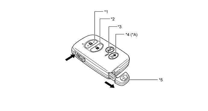
Text in Illustration *A Models with Panic Switch - - *1 Lock Switch *2 Unlock Switch *3 Remote Air Conditioning System Switch *4 Panic Switch *5 Mechanical Key - -
-
-
Power Switch
-
The power switch consists of a momentary type switch, indicator light (amber and green color LEDs), illumination, antenna coil and transponder key amplifier.
-
The driver can determine the present power source and check whether the hybrid control system can start or not in accordance with the illumination state of the indicator light.
-
When the power management control ECU detects an abnormality with the start function, it makes the amber indicator light flash. If the hybrid control system is stopped in this state, it might not be possible to restart it.
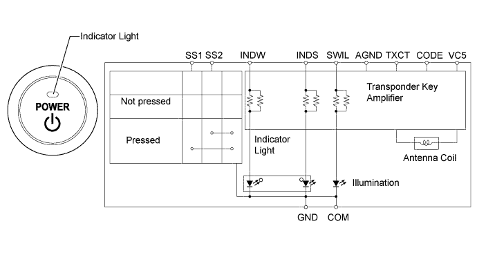
Power Source Condition Indicator Light Condition Brake pedal not depressed Park (P) selected with brake pedal depressed Off (LOCK) OFF ON (Green) On (ACC), On (IG) ON (Amber) ON (Green) On (READY) OFF Start Function Malfunction Flashes (Amber) for 15 seconds
-
-
-
DIAGNOSIS
-
When the power management control ECU and certification ECU (smart key ECU assembly) detects a malfunction in the entry and start system, the amber indicator light of the power switch flashes to warn the driver. At the same time, the ECUs store 5-digit Diagnostic Trouble Codes (DTC).
-
The indicator light warning continues for 15 seconds even after the power switch is turned to off.
-
The 5-digit DTCs can be read by connecting the Global Tech Stream (GTS) to the DLC3. For details, refer to the Repair Manual.
-