БЛОК ДВИГАТЕЛЯ ДЕТАЛЬНОЕ ОПИСАНИЕ
-
CONSTRUCTION
-
Cylinder Head Cover
-
A lightweight yet high-strength aluminum cylinder head cover is used.
-
An oil filler housing has been provided on the left bank cylinder head cover to improve the serviceability when filling the engine oil.
-
The cylinder head cover gasket and a gasket to seal the ignition coil circumference have been integrated to reduce the number of parts.

Text in Illustration *1 Cylinder Head Cover *2 Cylinder Head Cover Gasket *3 Oil Filler Housing - -
-
-
Cylinder Head Gasket
-
A steel-laminate type cylinder head gasket is used.
-
A shim has been added around the cylinder bore to increase the sealing surface, thus improving the sealing performance and durability.

Text in Illustration *1 Cylinder Head Gasket (Bank 1) *2 Cylinder Head Gasket (Bank 2) *3 Shim - - *a A - A Cross Section - - 
Engine Front - -
-
-
Cylinder Head
-
The cylinder head, which is made of aluminum, contains a pentroof type combustion chamber. The spark plug has been located in the center of the combustion chamber in order to improve the engine's anti-knocking performance.
-
The intake ports are on the inside and the exhaust ports are on the outside of the left and right banks respectively.
-
Upright intake ports are used to improve the intake efficiency.
-
A taper squish combustion chamber is used to improve anti-knocking performance and intake efficiency. In addition, engine performance and fuel economy have been improved.
-
A siamese type intake port is used to reduce the overall surface area of the intake port walls. This prevents the fuel from adhering onto the intake port walls, thus reducing HC exhaust emissions.

Text in Illustration *1 Intake Valve *2 Spark Plug Hole *3 Exhaust Valve *4 Upright Intake Port *5 Taper Squish - - *a Bottom Side View *b Intake Side *c Exhaust Side *d A - A Cross Section Tech Tips
The difference between a siamese type intake port and independent type one is shown in the illustration.

Text in Illustration *A Siamese Type *B Independent Type -
The cylinder head bolts have been positioned below the camshaft journal in the front of the right bank, and the holes for placing the bolts have been provided above the camshaft journal. Thus, the front end of the right bank has been shortened, resulting in a shorter overall length of the engine.

Text in Illustration *1 Cylinder Head (Bank 1) *2 Cylinder Head Bolt *3 Camshaft Journal - - *a Shortened - - Engine Front - -
-
-
Cylinder Block
-
The cylinder block is made of aluminum alloy.
-
The cylinder block has a bank angle of 60°, a bank offset of 36.6 mm (1.441 in.) and a bore pitch of 105.5 mm (4.15 in.), resulting in a compact block in its length and width even for its displacement.
-
Spiny-type liners are used.
-
Installation bosses of the two knock control sensors are located on the inner side of the left and right banks.

Text in Illustration *1 Knock Control Sensor Boss - - -
A water passage is provided between the cylinder bores. By allowing the engine coolant to flow between the cylinder bores, this construction keeps the temperature of the cylinder walls uniform.

Text in Illustration *1 Water Passage - - -
The liners are the spiny-type which have been manufactured so that their casting exteriors form large irregular surfaces in order to enhance the adhesion between the liners and the aluminum cylinder block. The enhanced adhesion helps heat dissipation, resulting in a lower overall temperature and heat deformation of the cylinder bores.

Text in Illustration *1 Cylinder Block *2 Liner *3 Irregularly Shaped Outer Casting Surface of Liner - - *a A - A Cross Section - -
-
-
Piston
-
The pistons are made of aluminum alloy.
-
The tops of the pistons use a taper squish shape to achieve fuel combustion efficiency.
-
The piston skirt is coated with resin to reduce friction losses.
-
The groove of the top ring is coated with alumite to ensure abrasion resistance.
-
This piston is common to all cylinders. Therefore, the pistons are not shaped especially for the right or the left bank. As a result, serviceability has been improved.
-
By increasing the machining precision of the cylinder bore diameter, the outer diameter of the piston has been made into one size.

Text in Illustration *a Taper Squish Shape - - 
Resin Coating 
Anodic Oxide Coating
-
-
Connecting Rod and Connecting Rod Bearing
-
Connecting rods that have been forged for high strength are used for weight reduction.
-
Knock pins are used at the mating surfaces of the bearing caps of the connecting rod to minimize the shifting of the bearing caps during assembly.
-
Plastic region tightening bolts are used.
-
An aluminum bearing is used for the connecting rod bearings.
-
The lining surface of the connecting rod bearing has been micro-grooved to achieve an optimal amount of oil clearance. As a result, cold-engine cranking performance has been improved and engine vibrations have been reduced.

Text in Illustration *1 Plastic Region Tightening Bolt *2 Knock Pin *3 Connecting Rod Bearing *4 Micro-grooved Surface
-
-
Crankshaft
-
A crankshaft made of forged steel, which excels in rigidity and wear resistance, is used.
-
The crankshaft has 4 journals and 5 balance weights.
-
All pin and journal fillets are roll-finished to maintain adequate strength.

Text in Illustration *1 No. 1 Journal *2 No. 2 Journal *3 No. 3 Journal *4 No. 4 Journal *5 Balance Weight - - *a Roll-finished - - Engine Front - -
-
-
Crankshaft Bearing and Crankshaft Bearing Cap
-
The crankshaft main bearings are made of aluminum alloy.
-
Similar to the connecting rod bearings, the lining surface of the crankshaft bearings is micro-grooved to achieve an optimal amount of oil clearance. As a result, cold-engine cranking performance is improved and engine vibration is reduced.
-
The upper crankshaft bearings have an oil groove around the inside circumference.
-
The crankshaft bearing caps are tightened using 4 plastic region tightening bolts for each journal. In addition, each cap is tightened laterally to improve its reliability.

Text in Illustration *1 Plastic Region Tightening Bolt *2 Crankshaft Bearing Cap *3 Upper Crankshaft Bearing *4 Lower Crankshaft Bearing *5 Oil Groove *6 Micro-grooved Surface
-
-
Crankshaft Pulley
-
The rigidity of the crankshaft pulley with its built-in torsional damper rubber reduces noise.

Text in Illustration *1 Torsional Damper Rubber - -
-
-
Oil Pan
-
No. 1 oil pan is made of aluminum alloy.
-
No. 2 oil pan is made of steel.
-
An oil passage has been integrated into No. 1 oil pan to simplify the construction of the oil strainer.
-
No. 1 oil pan is secured to the cylinder block and the torque converter housing in order to increase rigidity.

Text in Illustration *1 No. 1 Oil Pan *2 No. 2 Oil Pan *3 Oil Strainer - - *a A - A Cross Section - - Oil Passage - -
-
-
Valve Mechanism
-
Each cylinder of this engine has 2 intake valves and 2 exhaust valves. Intake and exhaust efficiency is increased due to the larger total port areas.
-
The valves are directly opened and closed by four camshafts.
-
The intake camshafts are driven by the crankshaft via the primary timing chain. The exhaust camshafts are each driven by the intake camshaft of their respective bank via a secondary chain.
-
The VVT-i system used for the intake camshaft achieves excellent fuel economy, higher engine performance and reduction of exhaust emissions.

Text in Illustration *1 No. 1 Camshaft (Intake) *2 No. 2 Camshaft (Exhaust) *3 Timing Chain (Primary) *4 Timing Chain (Secondary) *5 No. 4 Camshaft (Exhaust) *6 No. 3 Camshaft (Intake)
-
-
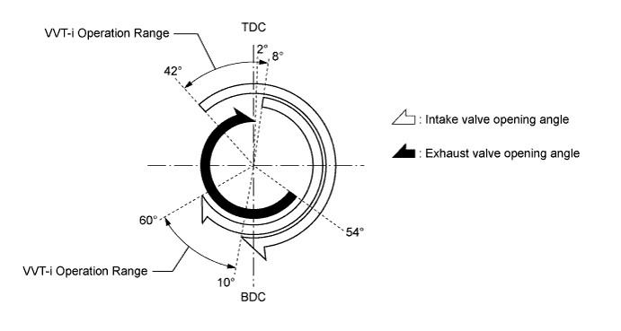
Valve Timing
-
Camshaft
-
The camshafts are made of cast iron alloy.
-
In conjunction with the use of the VVT-i system, an oil passage is provided in the intake camshaft in order to supply engine oil to the VVT-i system.
-
A VVT-i controller has been installed on the front of the intake camshaft to vary the timing of the intake valves.
-
To detect the intake camshaft position, a timing rotor is provided in front of the VVT-i controller. This timing rotor, which is secured to the intake camshaft, is used by the VVT sensor to detect the actual position of the intake camshaft.

Text in Illustration *1 No. 2 Camshaft (Exhaust) *2 No. 1 Camshaft (Intake) *3 VVT-i Controller *4 Timing Rotor *5 No. 3 Camshaft (Intake) *6 No. 4 Camshaft (Exhaust)
-
-
VVT-i Controller
-
This controller consists of the housing driven from the timing chain and the vane coupled with the intake camshaft.
-
The oil pressure sent from the advance or retard side path at the intake camshaft causes rotation in the VVT-i controller vane circumferential direction to vary the intake valve timing continuously. When the engine is stopped, the intake camshaft will be in the most retarded state to ensure startability.
-
When hydraulic pressure is not applied to the VVT-i controller immediately after the engine has started, the lock pin locks the movement of the VVT-i controller to prevent a knocking noise. Thereafter, when hydraulic pressure is applied to the VVT-i controller, the lock pin is released.

Text in Illustration *1 Timing Rotor *2 Outer Housing *3 Vane (Coupled to Intake Camshaft) *4 Lock Pin *5 Timing Chain Sprocket *6 Intake Camshaft *a Engine Operating *b Engine Stopped Oil Pressure - -
-
-
Timing Chain and Chain Tensioner
-
The primary and secondary timing chains are roller chains with a pitch of 9.525 mm (0.375 in.).
-
A chain tensioner is provided for each primary timing chain and secondary timing chain in each bank.
-
Both types of chain tensioner use a spring and oil pressure to maintain proper chain tension at all times. They suppress noise generated by the chains.
-
The chain tensioner for the primary timing chain is a ratchet type with a non-return mechanism. Furthermore, an oil pocket creates oil pressure when the engine is started, and simultaneously applies oil pressure to the chain tensioner. This prevents the timing chain from flapping and reduces noise.

Text in Illustration *1 Chain Tensioner (Secondary) *2 Ball *3 Ball Spring *4 Main Spring *5 Plunger *6 Chain Tensioner (Primary) *7 Spring *8 Cam Spring *9 Cam *10 Idle Sprocket *11 Chain Tensioner Slipper *12 Chain Vibration Damper *13 Timing Chain (Primary) *14 Timing Chain (Secondary)
-
-
Timing Chain Cover
-
The timing chain cover has an integrated construction consisting of the cooling system (water pump and water passage) and the lubrication system (oil pump and oil passage). Thus, the number of parts has been reduced to reduce weight.

Text in Illustration *1 Timing Chain Cover *2 Water Pump Gasket *3 Water Pump *4 Oil Passage *5 Oil Pump Rotor *6 Oil Pump Cover *a Water Pump Swirl Chamber *b Oil Pump Chamber
-
-
Valve and Valve Lifter
-
Valve lifters with shim-less valve adjustment are used for weight reduction.
-
Because the valve face diameter of the intake valves is greater than that of the exhaust valves, these valves contribute to improving intake efficiency.

Text in Illustration *1 Valve Lifter *2 Valve
-
-
V-ribbed Belt
-
Accessory components are driven by a serpentine belt consisting of a single V-ribbed belt. It reduces the overall engine length, weight and number of engine parts.
-
An automatic tensioner eliminates the need for tension adjustment.

Text in Illustration *1 Power Steering Pump Pulley *2 Belt Idler *3 Water Pump Pulley *4 Crankshaft Pulley *5 Idler Pulley for Automatic Tensioner *6 Air Conditioning Compressor Pulley *7 Alternator Pulley - - -
The tension of the V-ribbed belt is properly maintained by the tension spring that is enclosed in the belt tensioner.

Text in Illustration *1 Idler Pulley *2 Spring *3 Arm *4 Bracket *5 Fulcrum - - *a Cross Section - - Belt Tension Direction 
Belt Pulling Direction
-
-