HYBRID CONTROL SYSTEM DETAILS
-
FUNCTION OF MAIN COMPONENTS
-
The main components of the plug-in hybrid system have the following functions:
Component Function Power Management Control ECU
-
Performs comprehensive control of the hybrid system.
-
Information from various sensors as well as from ECUs (ECM, MG ECU, battery smart unit and skid control ECU) is received, and based on this the required torque and output power is calculated. The power management control ECU transmits the calculated result to the ECM, MG ECU and skid control ECU.
-
Monitors the SOC of the HV battery.
-
Controls the DC-DC converter.
-
Controls the inverter water pump assembly.
-
Controls the battery cooling blower assembly.
Hybrid Vehicle Transaxle Assembly Motor Generator No. 1 (MG1) MG1, which is driven by the engine, generates high-voltage electricity in order to operate MG2 and charge the HV battery. Also, it functions as a starter to start the engine. Motor Generator No. 2 (MG2)
-
MG2, which is driven by electrical power from MG1 and the HV battery, generates motive force for the drive wheels.
-
During braking, or when the accelerator pedal is not depressed, it generates high-voltage electricity to recharge the HV battery.
Generator Resolver (For MG1) Detects the rotor position, rotational speed and direction of MG1. Motor Resolver (For MG2) Detects the rotor position, rotational speed and direction of MG2. Generator Temperature Sensor (For MG1) Detects the temperature of MG1. Motor Temperature Sensor (For MG2) Detects the temperature of MG2. Compound Gear Unit Power Split Planetary Gear Unit Distributes the engine motive force as appropriate to directly drive the vehicle as well as MG1. Motor Speed Reduction Planetary Gear Unit Reduces the rotational speed of MG2 in accordance with the characteristics of the planetary gear, in order to increase torque. Inverter with Converter Assembly Inverter Converts the direct current from the boost converter into alternating current for MG1 and MG2, and vice versa (from AC to DC). Boost Converter Boosts the HV battery nominal voltage of DC 207.2 V up to a maximum voltage of DC 650 V and vice versa (steps down DC 650 V to DC 207.2 V). DC-DC Converter Steps down the HV battery nominal voltage of DC 207.2 V to approximately DC 14 V in order to supply electricity to the electrical components, as well as to recharge the auxiliary battery. MG ECU Controls the inverter and boost converter in accordance with the signals received from the power management control ECU, thus operating MG1 and MG2 as either a generator or motor. Atmospheric Pressure Sensor Detects the atmospheric pressure. Temperature Sensor for Inverter with Converter Assembly Detects temperatures in the parts of the inverter with converter assembly as well as the HV coolant temperature. Inverter Current Sensor Detects the current of MG1 and MG2. HV Battery Assembly Hybrid Battery Stack
-
Supplies electrical power to MG1 and MG2 in accordance with the driving conditions of the vehicle.
-
Recharged by MG1 and MG2 in accordance with the SOC and the driving conditions of the vehicle.
-
Accumulates power from the external power source supplied by plug-in charging.
HV Battery Temperature Sensor Detects temperatures in the parts of the HV battery. HV Battery Intake Air Temperature Sensor Detects the Intake air temperature from the battery cooling blower assembly. Hybrid Battery Junction Block Assembly System Main Relays Connects and disconnects the high-voltage circuit between the HV battery and the inverter with converter assembly through the use of signals from the power management control ECU. Battery Current Sensor Detects the input and output current of the HV battery. Battery Smart Unit
-
Monitors the conditions of the HV battery such as voltage, current and temperature, and transmits this information to the power management control ECU.
-
Monitors the high-voltage system for breakdown of the electrical insulation.
Service Plug Grip Shuts off the high-voltage circuit of the HV battery when the service plug grip is removed for vehicle inspection or maintenance. Interlock Switch (for Service Plug Grip/for Inverter Terminal Cover/for Power Cable Connector) Verifies that the service plug grip, inverter terminal cover and inverter power cable connector are installed. Power Cable (Frame Wire) Connects the HV battery, inverter with converter assembly, hybrid vehicle transaxle assembly and compressor with motor assembly. Inverter Water Pump Assembly Operates under the control of the power management control ECU in order to cool the inverter with converter assembly and MG1. Battery Cooling Blower Assembly Operates under the control of the power management control ECU in order to cool the HV battery. Auxiliary Battery Supplies electricity to the electrical components. Auxiliary Battery Temperature Sensor (Thermistor Assembly) Detects the temperature of the auxiliary battery. Power Switch Starts and stops the hybrid system. Accelerator Pedal Sensor Assembly Converts the accelerator pedal position into an electrical signal and sends it to the power management control ECU. Shift Lock Control Unit Assembly Shift Lever Position Sensor (Select Sensor) Converts the shift position (lateral movement) into electrical signals and sends them to the power management control ECU. Shift Lever Position Sensor (Shift Sensor) Converts the shift position (longitudinal movement) into electrical signals and sends them to the power management control ECU. P Position Switch (Transmission Shift Main Switch) Outputs the P position switch signal to the power management control ECU when operated by the driver. Stop Light Switch Detects the depression of the brake pedal. Integration Control and Panel Sub-assembly EV/HV Mode Selection Switch Sends the EV/HV mode selection switch signal to the power management control ECU when operated by the driver. EV CITY Mode Switch Sends the EV CITY mode switch signal to the power management control ECU via the ECM when operated by the driver. ECO Mode Switch Sends the ECO mode switch signal to the power management control ECU via the air conditioning amplifier assembly when operated by the driver. ECM
-
Performs control of the engine in accordance with the target engine speed and required engine motive force received from the power management control ECU.
-
Transmits various engine operating condition signals to the power management control ECU.
Skid Control ECU (Brake Booster with Master Cylinder Assembly)
-
During braking, it calculates the required regenerative braking force and transmits it to the power management control ECU.
-
Transmits the request to the power management control ECU to limit motive force while the TRC or VSC is operating.
Air Conditioning Amplifier Assembly Transmits various A/C state signals to the power management control ECU. Airbag ECU Assembly During a collision, it transmits the airbag deployment signal to the power management control ECU. Combination Meter Assembly READY Indicator Light Informs the driver that the vehicle is ready to drive. Shift Position Indicator Shows the shift state selected by the driver. EV MODE Indicator Light Informs the driver that EV drive mode is selected. EV CITY MODE Indicator Light Informs the driver that EV CITY mode is selected. ECO MODE Indicator Light Informs the driver that ECO mode is selected. Discharge Warning Light Turns on when there is a malfunction in the auxiliary battery charging system. Malfunction Indicator Lamp (MIL) Turns on when there is a malfunction in the hybrid control system and engine control system. Multi-information Display
-
The multi-information display displays messages to inform the driver when a malfunction occurs. It also displays system status and operation instructions.
-
The master warning light may illuminate or flash and the buzzer may sound depending on the message displayed on the multi-information display.
-
The power management control ECU displays the visual indicators that express the operating states of the hybrid system on the multi-information display. The visual indicators are as follows: Energy Monitor, Hybrid System Indicator and EV Drive Ratio.
-
The Eco driving indicator light is displayed on the Hybrid System Indicator during Eco-friendly acceleration (Eco driving).
-
The EV driving indicator light is displayed on the Hybrid System Indicator.
Radio and Display Receiver Assembly*1 Displays the energy monitor. Navigation Receiver Assembly*2 *1: Models with touch screen system and display audio system
*2: Models with HDD navigation system
-
-
-
OPERATING CONDITION
-
Plug-in Hybrid System Activation (READY-on State)
-
The plug-in hybrid system can be activated by pressing the power switch while the brake pedal is being depressed. At this time, the READY indicator light flashes until the system check is completed. When the READY indicator light turns on, the hybrid system starts and informs the driver that the vehicle is ready to drive.
-
Even if the driver turns the power switch on (READY), sometimes the power management control ECU will not start the engine. The engine will only start if conditions such as SOC, HV battery temperature, request from air conditioning system and electrical load require an engine start.
-
After driving, when the driver stops the vehicle and turns the P position switch (transmission shift main switch) on, the power management control ECU allows the engine to continue running. The engine will stop after the SOC, HV battery temperature and electrical load reach a specified condition level.
Note
When the hybrid system is unavoidably required to be stopped while driving, the system can be forced to stop by pressing and holding the power switch for approximately 2 seconds or more or pushing the power switch 3 times or more in a row. At this time, the power source will change to on (ACC).
-
-
Plug-in Charging
-
Charging is started by connecting the charging connector of a charging cable (electric vehicle charger cable assembly) connected to an external power source, to the charging inlet on the vehicle after stopping the hybrid system by pressing the power switch.
-
Plug-in charging can charge the HV battery from an external power source of AC 220 to 240V using the charging cable (electric vehicle charger cable assembly).
-
It takes approximately 90 minutes to complete charging of the battery when the vehicle is connected to an external power source of AC 220 to 240V using the charging cable (electric vehicle charger cable assembly). The charging indicator illuminates during charging and goes off when charging is complete.
-
Charging will be interrupted if the electric vehicle charger cable assembly is removed from the vehicle, and restarted by reconnecting the assembly.
-
-
EV Mode
-
EV mode is provided.
Driving Mode Variations State Detail EV Mode Driving status using mainly the plug-in charged electrical power for MG2 motive force. When in this mode, the EV driving mode indicator light illuminates. HV Mode (Same as Conventional Hybrid Vehicle Drive Mode) In a situation where the plug-in charged electrical power has been consumed, the system will optimally combine the motive force of the engine with that of MG2 to extend the traveling range. Also, if the State Of Charge (SOC) is higher than the predetermined level, it is possible to change to HV mode using the EV/HV mode selection switch. -
Even in EV mode, the engine will be started under any of the following conditions in order to protect parts and to ensure vehicle performance.
Engine Starting Conditions When driving at approximately 85 km/h (53 mph) or more.
-
When rapid acceleration is requested by accelerator pedal depression.
-
Accelerator pedal depression amount at high speed driving: Approximately 40%
-
Accelerator pedal depression amount at low speed driving: Approximately 80%
When the vehicle is stopped on a steep incline. When the system judges that the engine should be started due to air conditioning requirements such as the heater, defogger or defroster operation. When the HV battery temperature is low (-10 °C (14 °F) or lower). When the engine coolant temperature is low (-10 °C (14 °F) or lower). During the period after the engine starts until the engine is fully warmed-up. Other situations in which the system judges the engine should be started due to system protection requirements. -
-
-
EV CITY Mode
-
When all required conditions, some of which are listed below, are satisfied, EV CITY drive mode can be used.
Operating Condition When the HV battery temperature is -10 °C (14 °F) or higher. When the engine coolant temperature is -10 °C (14 °F) or higher. When driving at approximately 85 km/h (53 mph) or less. The SOC is approximately 23.4% or more. The accelerator pedal depression amount is approximately 90% or less. The defroster and defogger are off. When an engine start due to a system requirement is not necessary.
-
-
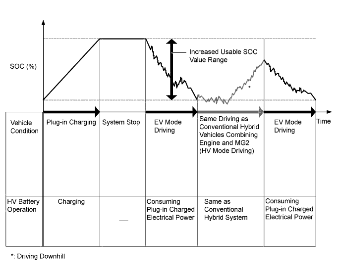
State Of Charge (SOC)
-
The power management control ECU estimates the SOC of the HV battery from the accumulated amperage that is constantly and repeatedly being charged and discharged. In order to maintain the SOC at the appropriate level all the time, the power management control ECU controls the hybrid system optimally.
-
The plug-in hybrid system usable SOC value range has been widened by allowing the HV battery to accumulate more electrical energy due to expansion of the HV battery capacity. As a result, EV mode driving performance is significantly improved.
-
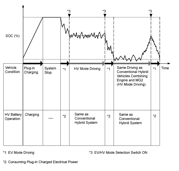
The user can control the HV battery operation as shown in the illustration using the EV/HV mode selection switch (integration control and panel sub-assembly).
-
-
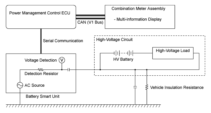
Detection of Insulation Resistance Decrease
-
The leak detection circuit is built in the battery smart unit. The leak detection circuit constantly monitors that the insulation resistance between high-voltage circuits and body ground is maintained.
-
The power management control ECU determines decreases in the insulation resistance based on the information from the battery smart unit.
-
The leak detection circuit has an AC source and causes a small amount of AC to flow to the high-voltage circuit (positive and negative).
-
The more vehicle insulation resistance decreases, the more voltage drops at the detection resistor and the lower the waves of AC. The insulation resistance value is detected based on the amplitude of AC waves.
-
-
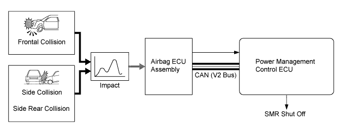
Cut-off of High-Voltage Circuits during Collision
-
If the vehicle encounters one of the situations described below, the power management control ECU will shut down the power supply by turning all SMR off, for safety.
-
The power management control ECU receives the airbag deployment signal from the airbag ECU assembly during a frontal collision, side collision or side rear collision.
-
-
-
SYSTEM CONTROL
-
Control List
-
The plug-in hybrid system consists of the controls listed below:
Control Outline Hybrid Vehicle Control
-
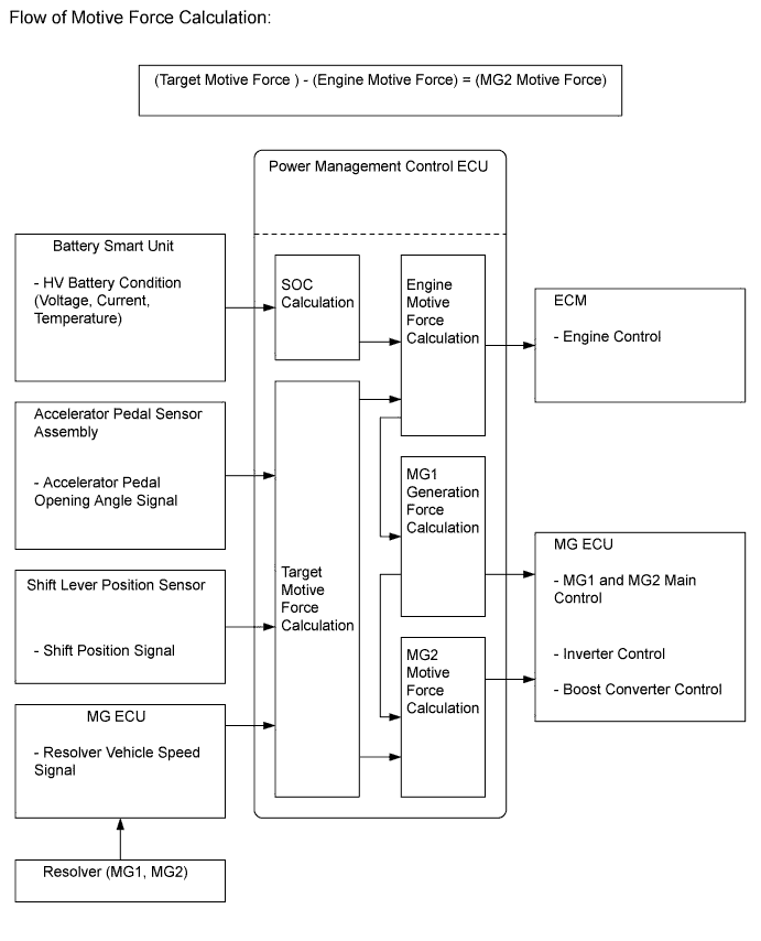
The power management control ECU calculates the target motive force based on the shift lever position sensor, the degree to which the accelerator pedal is depressed, and the vehicle speed. It performs control in order to create the target motive force by optimally combining MG1, MG2 and the engine.
-
The power management control ECU calculates the engine motive force based on the target motive force, which has been calculated based on the requirements of the driver and the driving conditions of the vehicle. In order to create this motive force, the power management control ECU transmits the signals to the ECM.
-
The power management control ECU monitors the SOC of the HV battery and the temperature of the HV battery, MG1 and MG2, in order to optimally control these items.
SOC Control
-
The power management control ECU calculates the SOC by estimating the charging and discharging amperage of the HV battery.
-
The power management control ECU constantly performs charge/discharge control based on the calculated SOC in order to maintain the SOC within its target range.
Engine Control The ECM receives the target engine speed and required engine motive force, which were sent from the power management control ECU, and controls the ETCS-i, fuel injection volume, ignition timing, VVT-i and EGR. MG1 and MG2 Main Control
-
MG1, which is driven by the engine, generates high-voltage electricity in order to operate MG2 and charge the HV battery. Also, it functions as a starter to start the engine.
-
MG2, which is driven by electrical power from MG1 and the HV battery, generates motive force for the drive wheels.
-
MG2 generates high-voltage electricity to charge the HV battery during braking (regenerative brake cooperative control), or when the accelerator pedal is not being depressed (energy regeneration).
-
MG1 and MG2 are basically shut down when the shift position is in N. In order to stop providing motive force, it is necessary to stop driving MG1 and MG2, because MG1 and MG2 are mechanically joined to the drive wheels.
Inverter Control
-
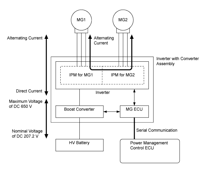
The inverter converts the direct current from the HV battery into the alternating current for MG1 and MG2, or vice versa, in accordance with the signals provided by the power management control ECU via the MG ECU. In addition, the inverter is used to transfer power from MG1 to MG2.
-
The power management control ECU shuts down the inverter if it receives the overheating, overcurrent or fault voltage signal from the inverter via the MG ECU.
Boost Converter Control
-
The boost converter boosts the HV battery nominal voltage of DC 207.2 V up to a maximum voltage of DC 650 V, in accordance with the signals provided by the power management control ECU via the MG ECU.
-
The inverter converts the alternating current generated by MG1 or MG2 into the direct current. The boost converter steps down the generated voltage of DC 650 V (maximum voltage) to approximately DC 207.2 V, in accordance with the signals provided by the power management control ECU via the MG ECU.
DC-DC Converter Control The DC-DC converter steps down the HV battery nominal voltage of DC 207.2 V to approximately DC 14 V in order to supply electricity to the electrical components, as well as to recharge the auxiliary battery. System Main Relay (SMR) Control To ensure that it is possible to connect and disconnect the high-voltage circuits reliably, the power management control ECU controls the 3 system main relays to connect and disconnect the high-voltage circuits from the HV battery. The power management control ECU also uses the timing of the operation of the 3 system main relays to monitor the operation of the relay contacts. Cooling System (for Inverter with Converter Assembly and MG1) Control In order to cool the inverter with converter assembly and MG1, the power management control ECU regulates the HV water pump with motor according to the signals from the temperature sensor (for inverter with converter assembly), temperature sensor (for MG1) and temperature sensor (for MG2). Cooling System (for HV Battery) Control In order to maintain the HV battery temperature at the optimum level, the power management control ECU regulates the HV battery cooling blower according to the signal from the HV battery temperature sensor. Regenerative Brake Cooperative Control During braking, the skid control ECU calculates the required regenerative braking force and transmits it to the power management control ECU. Upon receiving this signal, the power management control ECU transmits the actual regenerative brake control value to the skid control ECU. Based on this result, the skid control ECU calculates and executes the required hydraulic braking force. TRC/VSC Cooperative Control The skid control ECU transmits the request to the power management control ECU to limit motive force while the TRC or VSC is operating. The power management control ECU controls the engine and MG2 in accordance with the present driving conditions in order to suppress the motive force. For details, see the Brake Control System. During Collision Control During a collision, if the power management control ECU receives the airbag deployment signal from the airbag ECU assembly, it turns the SMR off in order to shut off the high-voltage from the HV battery. Cruise Control System Operation Control*1 When the power management control ECU receives the cruise control main switch signal, it controls the motive forces of the engine and MG2 to be an optimum combination in order to obtain the target vehicle speed by the driver's demand. For details, see the Cruise Control System. Dynamic Radar Cruise Control System Operation Control*2 Upon receiving the motive force request signal from the driving support ECU, the power management control ECU controls the motive forces of the engine and MG2 to be an optimum combination in order to obtain the target vehicle speed. For details, refer to Dynamic Radar Cruise Control System. Shift Control The power management control ECU detects the shift position (P, R, N, D or B) in accordance with the signals provided by the shift lever position sensor and P position switch (transmission shift main switch). The power management control ECU controls MG1, MG2 and the engine to match the selected shift position. EV Drive Mode Control
-
While driving, the vehicle switches between EV mode and HV mode in accordance with the SOC of the HV battery. Switching from EV mode to HV mode is automatically performed according to the SOC of the battery.
-
While driving in EV mode, the mode can be manually changed to HV mode using the EV/HV mode selection switch (integration control and panel sub-assembly). The driver can preserve the SOC of the HV battery by selecting HV mode in situations such as when driving at high speeds, which quickly drains the battery. This enables the driver to control the battery usage by themselves.
EV CITY Mode Control When the EV CITY drive mode switch (integration control and panel sub-assembly) is operated by the driver, the power management control ECU uses only MG2 to drive the vehicle if the operating conditions are satisfied. ECO Mode Control When the ECO mode switch (integration control and panel sub-assembly) is operated by the driver, the power management control ECU moderates the response of the accelerator pedal operation to support Eco driving. Brake Override System Restricts the driving torque when the brake pedal is depressed while the accelerator pedal is depressed. (For the Activation Conditions and Inspection Method, refer to the Repair Manual) Engine Immobiliser Prohibits fuel delivery, ignition and starting the hybrid control system if an attempt is made to start the hybrid control system with an invalid key. *1: Models with cruise control system
*2: Models with dynamic radar cruise control system
-
-
-
Hybrid Vehicle Control
-
The power management control ECU detects the amount of accelerator pedal depression using the signals from the accelerator pedal position sensor and detects the shift position signals from the shift lever position sensor. The power management control ECU receives the resolver vehicle speed signals from the MG1 and MG2 resolvers via the MG ECU. The power management control ECU determines the driving conditions of the vehicle in accordance with this information, and optimally controls the motive forces of MG1, MG2 and the engine. Furthermore, the power management control ECU optimally controls the output and torque of MG1, MG2 and the engine in order to deliver lower fuel consumption and cleaner exhaust emissions.
-
The power management control ECU calculates the engine motive force based on the calculated target motive force, and by taking the SOC and the temperature of the HV battery into consideration. The value obtained by subtracting the engine motive force from the target motive force is the MG2 motive force.
-
The ECM performs control of the engine in accordance with the target engine speed and required engine motive force received from the power management control ECU. Furthermore, the power management control ECU appropriately operates MG1 and MG2 in order to provide the required MG1 generation force and the required MG2 motive force.
-
-
SOC Control
-
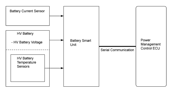
The power management control ECU calculates the SOC of the HV battery based on the charge/discharge amperages detected by the HV battery current sensor. The power management control ECU constantly performs charge/discharge control based on the calculated SOC in order to maintain the SOC within its target range.
-
While the vehicle is in motion, the HV battery undergoes repetitive charge/discharge cycles, as it becomes discharged by MG2 during acceleration and charged by regenerative braking during deceleration.
-
When the SOC is below the lower level, the power management control ECU increases the power output of the engine to operate MG1, which charges the HV battery.
-
The battery smart unit converts the HV battery related signals (voltage, current and temperature) into digital signals, and transmits them to the power management control ECU via serial communication. These signals are needed to determine the SOC that is calculated by the power management control ECU.
-
-
Engine Control
-
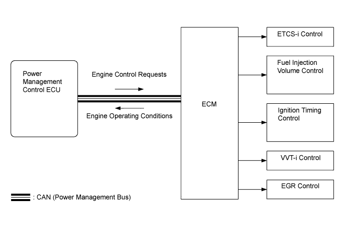
The ECM receives the target engine speed and required engine motive force, which were sent from the power management control ECU, and controls the ETCS-i, fuel injection volume, ignition timing, VVT-i and EGR.
-
The ECM transmits the operating condition of the engine to the power management control ECU.
-
Upon receiving the engine stop signal from the power management control ECU in accordance with the basic hybrid vehicle control, the ECM will stop the engine.
-
-
MG1 and MG2 Main Control
-
MG1, which is driven by the engine, generates high-voltage electricity in order to operate MG2 and charge the HV battery. Also, it functions as a starter to start the engine.
-
MG2, which is driven by electrical power from MG1 and the HV battery, generates motive force for the drive wheels.
-
MG2 generates high-voltage electricity to charge the HV battery during braking (regenerative brake cooperative control), or when the accelerator pedal is not being depressed (energy regeneration).
-
MG1 and MG2 are basically shut down when the shift position is in N. In order to stop providing motive force, it is necessary to stop driving MG1 and MG2, because MG1 and MG2 are mechanically joined to the drive wheels.
-
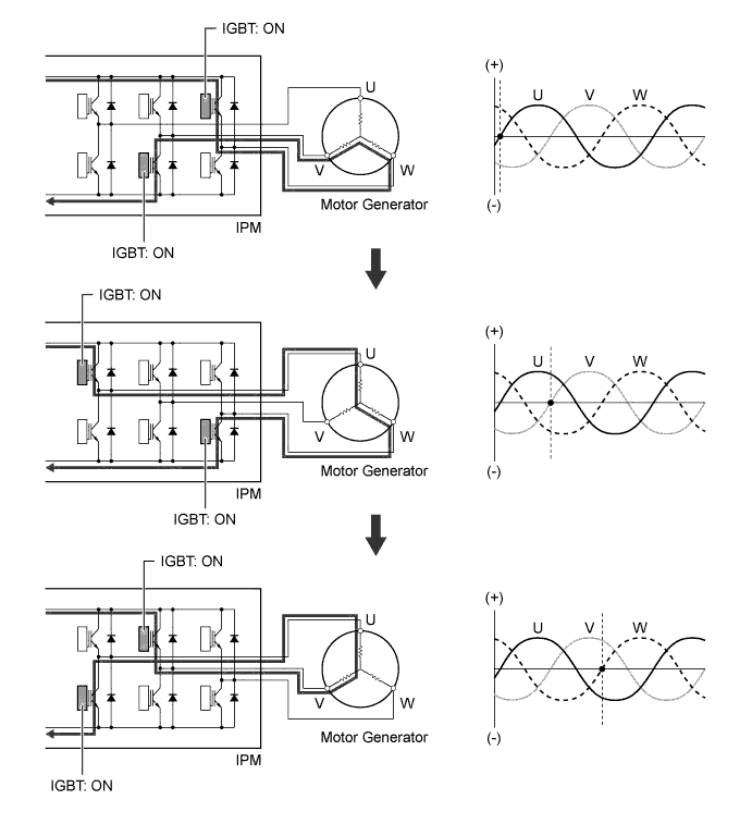
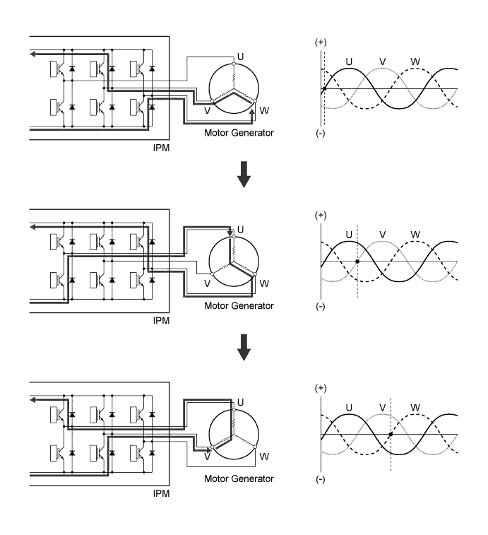
The MG ECU controls the Insulated Gate Bipolar Transistors (IGBTs) in the Intelligent Power Module (IPM) for switching the U, V and W phases of motor generator in accordance with the signals received from the power management control ECU. The 6 IGBTs switch on and off to control each individual motor generator in accordance with operation as either a motor or as a generator.
-
The illustration below describes the basic control used when the motor generator functions as a motor. The IGBTs in the IPM switch on and off to supply three-phase alternating current to the motor generator. In order to create the motive force required of the motor generator as calculated by the power management control ECU, the MG ECU switches the IGBTs on and off and controls the speed, in order to control the speed of the motor generator.
-
The illustration below describes the basic control used when the motor generator functions as a generator. The current that is generated sequentially by the 3 phases of the motor generator, which is driven by the wheels, is utilized to charge the HV battery or drive another motor generator.
-
-
Inverter Control
-
The inverter converts the direct current from the HV battery into alternating current for MG1 and MG2, or vice versa. In addition, the inverter takes power generated by MG1 and supplies it to MG2. However, the electricity generated by MG1 is converted into the direct current inside the inverter before being converted back into the alternating current by the inverter for use by MG2. This is necessary because the frequency of the alternating current output by MG1 is not appropriate for control of MG2.
-
The MG ECU controls the IPMs for switching the three-phase alternating current of MG1 and MG2 in accordance with the signals received from the power management control ECU.
-
When the power management control ECU has received an overheating, overcurrent, or fault voltage signal from the MG ECU, the power management control ECU transmits a shut down control signal to the MG ECU, in order to turn off the IPMs.
-
-
Boost Converter Control
-
The boost converter boosts the HV battery nominal voltage of DC 207.2 V up to a maximum voltage of DC 650 V, in accordance with the signals provided by the power management control ECU via the MG ECU.
-
The inverter converts the alternating current generated by MG1 or MG2 into direct current. The boost converter steps down the generated voltage of DC 650 V (maximum voltage) to approximately DC 207.2 V, in accordance with the signals provided by the power management control ECU via the MG ECU.
-
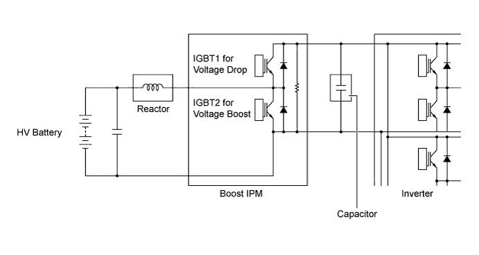
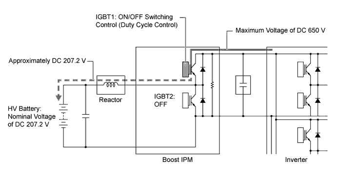
The boost converter consists of the boost IPM with built-in IGBTs that perform switching control, the reactor that stores the electrical power and generates the electromotive force, and the capacitor that charges and discharges the boosted high-voltage electricity.
-
The flow of the boost converter boosting is as described below.
Step Outline 1 The IGBT2 turns on, causing the voltage of the HV battery (nominal voltage of DC 207.2 V) to charge the reactor. As a result, the reactor stores the electrical power. 2 The IGBT2 turns off, causing the reactor to produce an electromotive force (the current continues to flow from the reactor). This electromotive force causes the voltage to rise to a maximum voltage of DC 650 V. Induced by the electromotive force that is created by the reactor, the current that is flowing from the reactor flows into the inverter and the capacitor at the boosted voltage. 3 The IGBT2 turns on again to cause the voltage of the HV battery to be charged into the reactor. For the duration, by discharging the electrical power (maximum voltage of DC 650 V) stored in the capacitor, the electrical power will be supplied to the inverter. 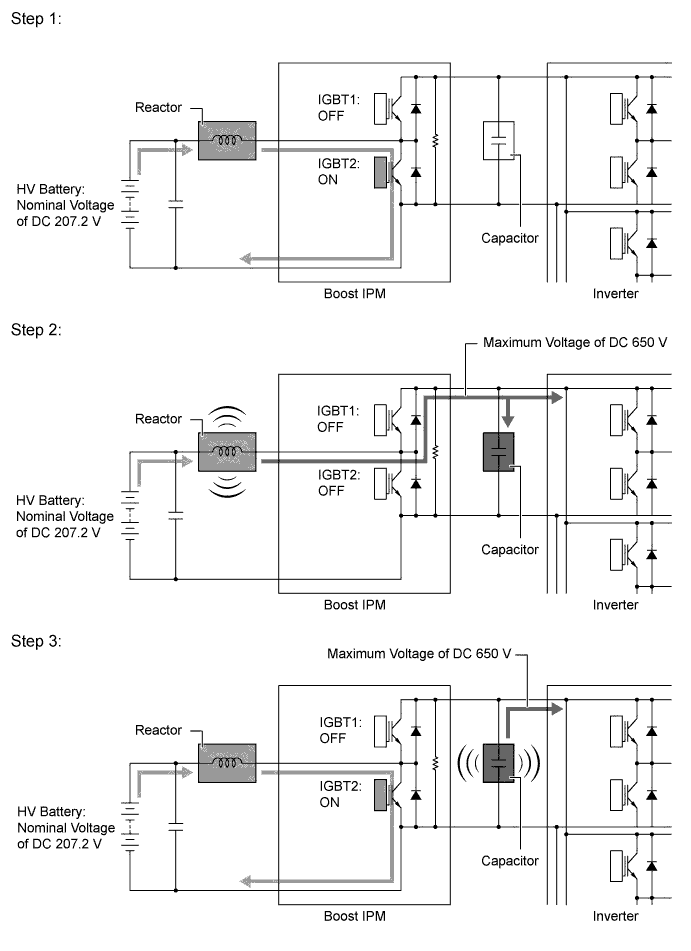
-
The alternating current which is generated by MG1 or MG2 for the purpose of charging the HV battery is converted into direct current (maximum voltage of DC 650 V) by the inverter. Then, the boost converter is used to step down the voltage to approximately DC 207.2 V. This is accomplished by IGBT1 being switched on and off using duty cycle control, intermittently interrupting the electrical power provided to the reactor by the inverter.
-
-
DC-DC Converter Control
-
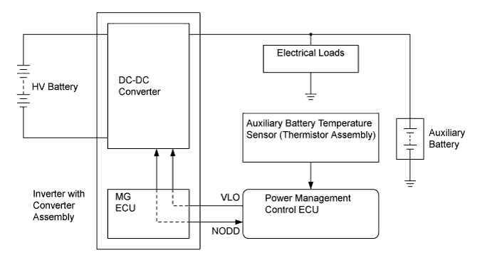
The DC-DC converter steps down the HV battery nominal voltage of DC 207.2 V to approximately DC 14 V in order to supply electricity to the electrical components, as well as to recharge the auxiliary battery.
-
In order to regulate the output voltage from the DC-DC converter, the power management control ECU transmits an output voltage request signal to the DC-DC converter in response to auxiliary battery temperature sensor signals.
-
-
System Main Relay (SMR) Control
-
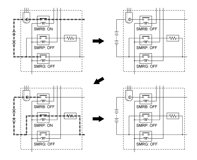
The power management control ECU controls the system main relays to connect and disconnect the high-voltage circuit from the HV battery. The power management control ECU also uses the timing of the operation of the system main relays to monitor the operation of the relay contacts.
-
A total of 3 relays, 1 for the positive side (SMRB), and 2 for the negative side (SMRP, SMRG), are provided to ensure proper operation.
-
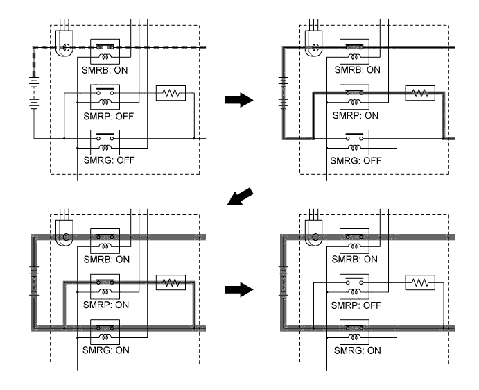
When the hybrid system changes to the READY-on state, the power management control ECU turns on SMRB and SMRP in sequence, and applies the current through the precharge resistor. After that, it turns SMRG on, and applies the current by bypassing the precharge resistor. Then it turns SMRP off. As the controlled current is initially allowed to pass through the precharge resistor in this manner, the contact point in the circuit is protected from damage that could be caused by an inrush current.
-
When the hybrid system changes to a state other than the READY-on state, the power management control ECU turns SMRG off first. Next, it turns SMRB off after determining whether or not SMRG is operating properly. After that, it turns on SMRP and then off after determining whether or not SMRB is operating properly. As a result, the power management control ECU verifies that the respective relays have been properly turned off.
-
-
Cooling System Control for Inverter with Converter Assembly and MG1
-
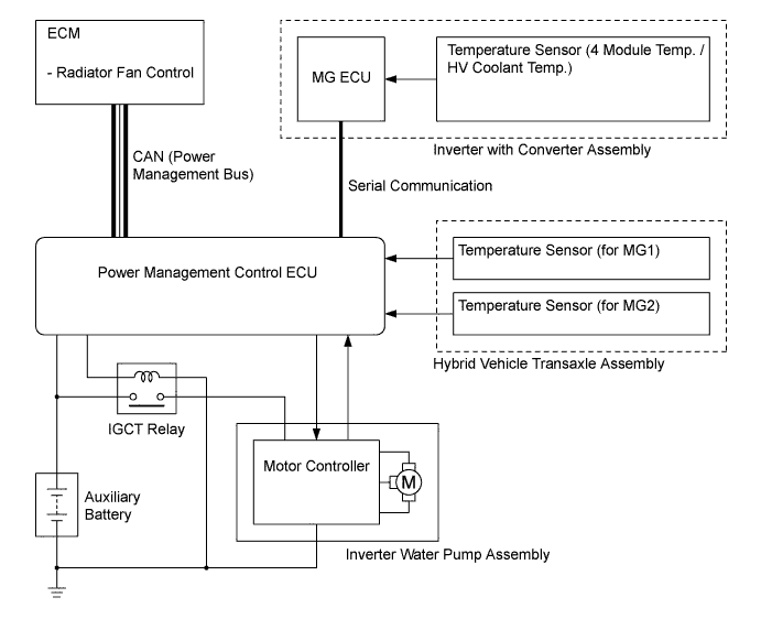
The power management control ECU receives the signals from the temperature sensor (for inverter with converter assembly), temperature sensor (for MG1) and temperature sensor (for MG2). Then, the power management control ECU actuates the HV water pump with motor over 3 levels using duty cycle control, in order to cool the inverter with converter assembly and MG1.
-
When the HV coolant temperature rises above a certain level, the power management control ECU transmits a radiator fan drive request signal to the ECM. In response to that reception signal, the ECM actuates the radiator fan to restrain the HV coolant temperature increases, ensuring the cooling of the inverter with converter assembly and MG1.
-
The MG ECU converts the temperature sensor signals into digital signals, and transmits them to the power management control ECU via serial communication.
-
-
Cooling System Control for HV Battery
-
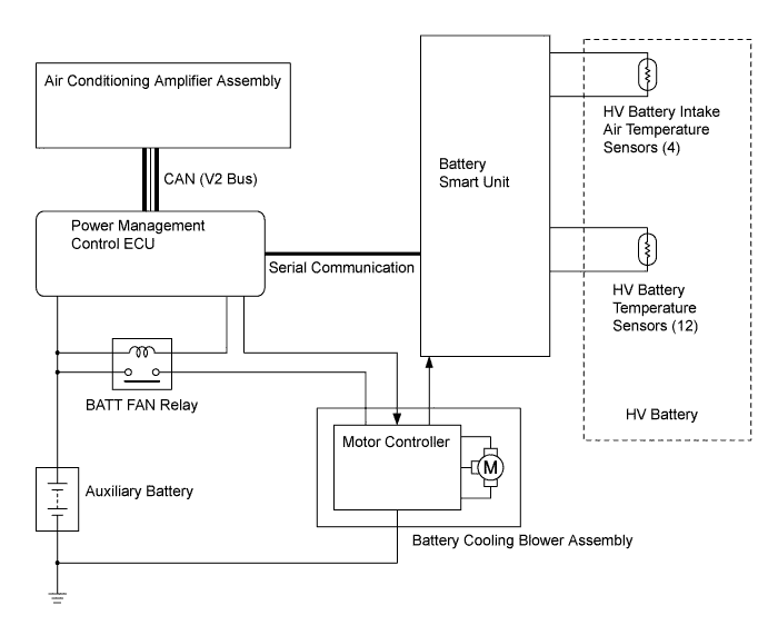
The power management control ECU receives the signals from the HV battery temperature sensors and HV battery intake air temperature sensor. Then, the power management control ECU steplessly actuates the battery cooling blower assembly using duty cycle control, in order to maintain the HV battery temperature within the specified range.
-
While the air conditioning system is operating and cooling down the cabin, if there is any leeway in the HV battery temperature, the power management control ECU turns the battery cooling blower assembly off or sets it to a low speed. The purpose of this control is to give priority to cooling down the cabin. If this control is not performed, air taken from the cabin for battery cooling assembly would slow the cooling of the cabin by the air conditioning system.
-
The battery smart unit converts the HV battery related signals (voltage, current and temperature) into digital signals, and transmits them to the power management control ECU via serial communication. Also, the battery smart unit detects and transmits the blower speed feedback voltage, which is necessary to perform the cooling system control, to the power management control ECU.
-
-
Regenerative Brake Cooperative Control
-
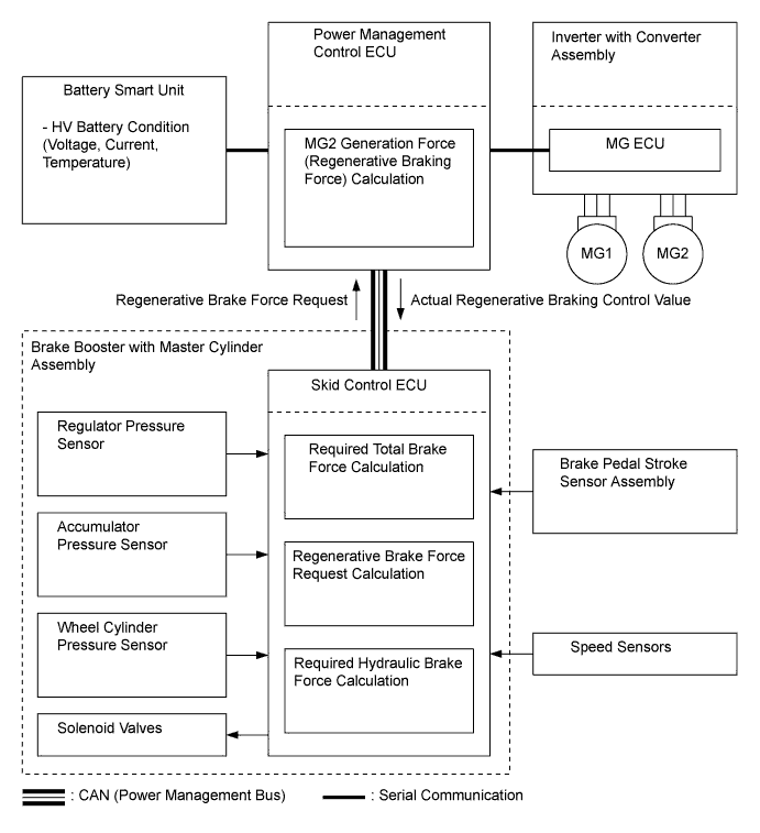
The skid control ECU calculates the total braking force needed based on the brake regulator pressure and brake pedal stroke when the driver depresses the brake pedal.
-
After calculating the required total braking force, the skid control ECU sends the regenerative braking force request to the power management control ECU. The power management control ECU replies with the amount of regenerative braking force that is possible.
-
The power management control ECU uses MG2 to create the negative torque (deceleration force), thus carrying out the regenerative braking.
-
The skid control ECU controls the brake actuator solenoid valves and generates wheel cylinder pressure. The pressure that is generated is what remains after the actual regenerative brake control value has been subtracted from the required total braking force.
-
-
EV Drive Mode Control
-
While driving, the vehicle switches between EV mode and HV mode in accordance with the SOC of the HV battery. Switching from EV mode to HV mode is automatically performed according to the SOC of the battery.
-
While driving in EV mode, the mode can be manually changed to HV mode using the EV/HV mode selection switch (integration control and panel sub-assembly). The driver can preserve the SOC of the HV battery by selecting HV mode in situations such as when driving at high speeds, which quickly drains the battery. This enables the driver to control the battery usage by themselves.
-
If any condition does not meet the operating conditions while the vehicle is traveling in EV drive mode, in order to inform the driver that EV drive mode will be canceled, the EV driving mode indicator light flashes 3 times and a buzzer* sounds. When the EV drive mode has automatically canceled, another message* is displayed to indicate that the EV drive mode has been canceled.
*: However, if EV mode is automatically changed to HV mode due to a decreased SOC, a buzzer does not sound and a message does not appear.
-
-
EV CITY Drive Mode Control
-
EV CITY drive mode has been provided to reduce vehicle noise, such as when entering or leaving a garage, as well as reducing the production of exhaust fumes in an urban area. When the EV CITY drive mode switch is operated by the driver, the power management control ECU uses only MG2 to drive the vehicle if the operating conditions are satisfied.
-
When all operating conditions are satisfied, pressing and holding the EV CITY drive mode switch causes the vehicle to enter EV CITY drive mode, and the EV CITY drive mode indicator light will be illuminated. If any operating condition is not satisfied and the EV CITY drive mode switch is pressed, a message is displayed on the multi-information display to inform the driver that the EV CITY drive mode switch operation was rejected, and EV CITY drive mode cannot be entered.
-
If the operating conditions are no longer met while the vehicle is traveling in EV CITY drive mode, in order to inform the driver that EV CITY drive mode will be canceled, the EV CITY drive mode indicator light goes off and a buzzer sounds. When EV CITY drive mode has automatically canceled, a message is displayed on the multi-information display to indicate that EV CITY drive mode has been canceled.
-
-
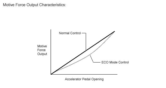
ECO Mode Control
-
During ECO mode, the power management control ECU optimizes fuel economy and driving performance by gently generating the motive force output against the accelerator pedal operation. At the same time, it supports Eco driving by optimizing the air conditioning performance.
-
-
-
FUNCTION
-
Messages of Multi-information Display
-
The multi-information display displays messages to inform the driver when a malfunction occurs. It also displays system status, plug-in charging states and operation instructions.
-
The master warning light may illuminate or flash and the buzzer may sound depending on the message displayed on the multi-information display.
Message Message Content Explanation Master Warning Light Buzzer SHIFT TO P POSITION WHEN STARTING The park (P) shift position must be selected when activating the hybrid system. Flashes Sounds SHIFT TO P POSITION WHEN PARKED The park (P) shift position must be selected while the vehicle is stopped. Flashes Sounds CHECK HYBRID SYSTEM STOP THE VEHICLE IN A SAFE PLACE The hybrid system is malfunctioning. Illuminates Sounds HAVE TRACTION BATTERY INSPECTED Inspection or replacement time of the HV battery is approaching. - - VEHICLE START WILL SOON BE DISABLED HAVE TRACTION BATTERY INSPECTED HV battery inspection or replacement time has come. - - VEHICLE START DISABLED UNTIL TRACTION BATTERY INSPECTED Restarting of the hybrid system is not possible. - - HYBRID SYSTEM OVERHEAT The temperatures of any parts related to the hybrid system exceed the specified value. Illuminates Sounds TRACTION BATTERY POWER LOW CHARGE WHEN NOT IN N POSITION The HV battery is low. Illuminates Sounds TRACTION BATTERY PROTECTION MODE RESTART AFTER SHIFTING TO P POSITION The HV battery power has dropped because a long period of time has elapsed after selecting the neutral (N) shift position. Flashes Sounds EV MODE NOT AVAILABLE EV drive mode is not available because all operating conditions have not been met. - - EV MODE CURRENTLY NOT AVAILABLE HEATER ON EV drive mode is not available because the heater is on. - Sounds EV MODE DEACTIVATED HEATER ON EV drive mode is not available because the heater is on. - Sounds EV MODE DEACTIVATED EV drive mode is deactivated because the vehicle no longer satisfies other operating conditions. - - PRESS & HOLD EV CITY SWITCH TO CHANGE TO EV CITY MODE To change to EV CITY mode, press and hold the EV CITY mode switch. - Sounds EV CITY MODE NOT AVAILABLE HEATER ON EV CITY mode is not available because the heater is on. - Sounds EV CITY MODE NOT AVAILABLE EXCESSIVE ACCELERATION EV CITY mode is not available because the accelerator pedal is depressed excessively. - Sounds EV CITY MODE NOT AVAILABLE EXCESSIVE SPEED Changing to EV CITY mode is not available because vehicle speed has exceeded the speed limit of EV CITY mode. - Sounds EV CITY MODE NOT AVAILABLE LOW BATTERY Changing to EV CITY mode is not available because the HV battery is low. - Sounds EV CITY MODE NOT AVAILABLE WARMING UP Changing to EV CITY mode is not available because the engine is warming up. - Sounds EV CITY MODE NOT AVAILABLE Changing to EV CITY mode is not available. - Sounds EV CITY MODE NOT AVAILABLE BATTERY TEMPERATURE LOW Changing to EV CITY mode is not available because the HV battery temperature is low. - Sounds EV CITY MODE DEACTIVATED HEATER ON EV CITY mode has been canceled because the heater is on. - Sounds EV CITY MODE DEACTIVATED EXCESSIVE ACCELERATION EV CITY mode has been canceled because the accelerator pedal is depressed excessively. - Sounds EV CITY MODE DEACTIVATED EXCESSIVE EV CITY SPEED EV CITY mode has been canceled because vehicle speed has exceeded the speed limit of EV city mode. - Sounds EV CITY MODE DEACTIVATED LOW BATTERY EV CITY mode has been canceled because the HV battery is low. - Sounds EV CITY MODE DEACTIVATED BATTERY TEMPERATURE LOW EV CITY mode has been canceled because the HV battery temperature is low. - Sounds EV CITY MODE DEACTIVATED EV CITY mode has been canceled - Sounds CHARGE RESULT: CHARGE COMPLETE The HV battery is fully charged and the plug-in charging is complete. - - CHARGE RESULT: CHARGE STOPPED TO PROTECT BATTERY DUE TO HI ELEC. CONSUMP. Charging has stopped due to high electricity consumption in order to protect the HV battery. - - CHARGE RESULT: CHARGE STOPPED DUE TO CHARGE CONNECTOR OPERATION Charging has stopped due to charging connector being disconnected. - - CHARGE RESULT: CHARGE STOPPED DUE TO OUTAGE OR PLUG REMOVE Charging has stopped due to a power outage or the plug being disconnected. - - CHARGE RESULT: CHARGE STOPPED DUE TO INSUFF. POWER SUPPLY Charging has stopped due to insufficient power from the power supply. - - CHARGE RESULT: CHARGE STOPPED DUE TO CHARGE CABLE OR OTHER Charging has stopped due to other causes, such as a charging cable malfunction. - - CHARGE RESULT: CHARGE COMPLETE (RESTRICTED DUE TO BATT. TEMP.) Charging is completed due to the HV battery temperature exceeding the threshold. - - CHARGE RESULT: CHARGE STOPPED DUE TO SYSTEM MALFUNCTION Charging has stopped due to a system malfunction. - - RECHARGE INLET DOOR IS OPEN The charging port lid is open. - -
-
-
Energy Monitor
-
The energy monitor display on the multi-information display visualizes the system energy flow the same as a conventional hybrid vehicle. Additionally, it shows the distance to empty for EV drive, in which the vehicle is driven using only MG2 motive force.
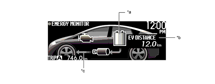
Text in Illustration *a Display of SOC Level *b EV Driving Range *c Display of Energy Flow - - -
During plug-in charging, the energy monitor displays a plug icon and approximate time until charging completes.
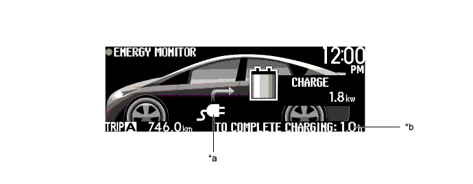
Text in Illustration *a Plug Icon *b Time until Plug-in Charging Completes -
The energy monitor displayed in the radio and display receiver assembly*1 or navigation receiver assembly*2 shows the energy flow of the hybrid system and the SOC of the HV battery in 8 levels based on information from the power management control ECU.
*1: Models with touch screen system or display audio system
*2: Models with HDD navigation system
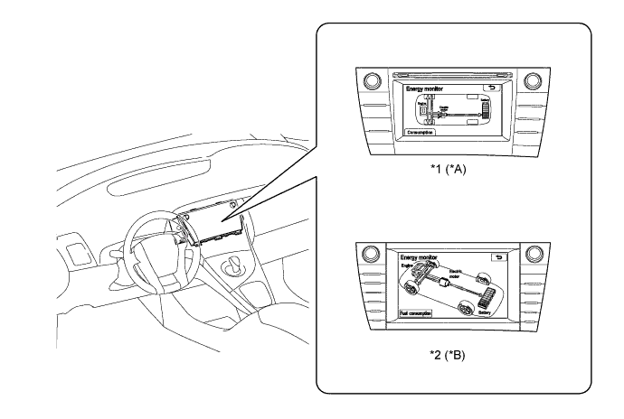
Text in Illustration (LHD Models:) *A Models with Touch Screen System *B Models with HDD Navigation System *1 Radio and Display Receiver Assembly *2 Navigation Receiver Assembly 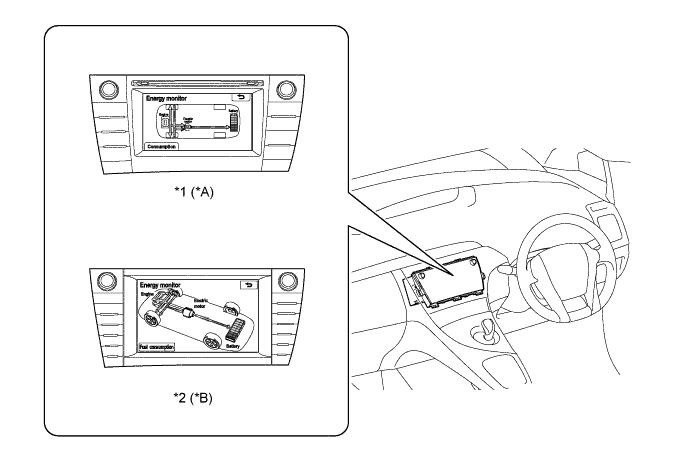
Text in Illustration (RHD Models:) *A Models with Touch Screen System or Display Audio System *B Models with HDD Navigation System *1 Radio and Display Receiver Assembly *2 Navigation Receiver Assembly
-
-
Hybrid System Indicator
-
Hybrid System Indicator, which is displayed on the multi-information display, has 2 display modes, an HV mode and an EV/EV CITY mode. The EV driving range is displayed on the EV/EV CITY mode display.
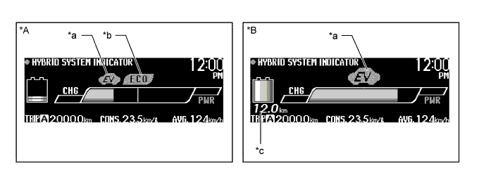
Text in Illustration *A HV Mode *B EV/EV CITY Mode *a EV Driving Indicator Light *b Eco Driving Indicator Light *c EV Driving Range - -
-
-
EV Driving Ratio
-
The EV Driving Ratio displays EV and HV mode driving distance ratios for the actual traveling distance in values and a bar graph.
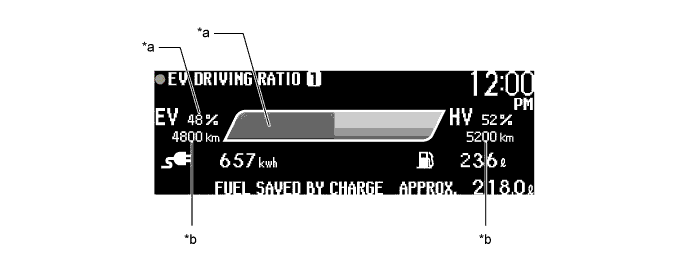
Text in Illustration *a EV Driving Ratio *b Actual Traveling Distance
-
-
-
CONSTRUCTION
-
Motor Generator No. 1 (MG1) and Motor Generator No. 2 (MG2)
-
MG1 and MG2, which are built into the hybrid vehicle transaxle assembly, are compact, lightweight and highly efficient alternating current permanent magnet motors.
-
MG1 and MG2 respectively consist of a stator, stator coil, rotor, permanent magnets and resolver.
-
MG1 charges the HV battery and supplies electrical power to drive MG2. In addition, MG1 regulates the generated electricity to change its speed, controlling the continuously variable transmission function of the transaxle effectively. MG1 also serves as the starter to start the engine.
-
MG2 drives the drive wheels using electrical power from MG1 or the HV battery. In addition, it acts as a generator when decelerating to charge the HV battery.
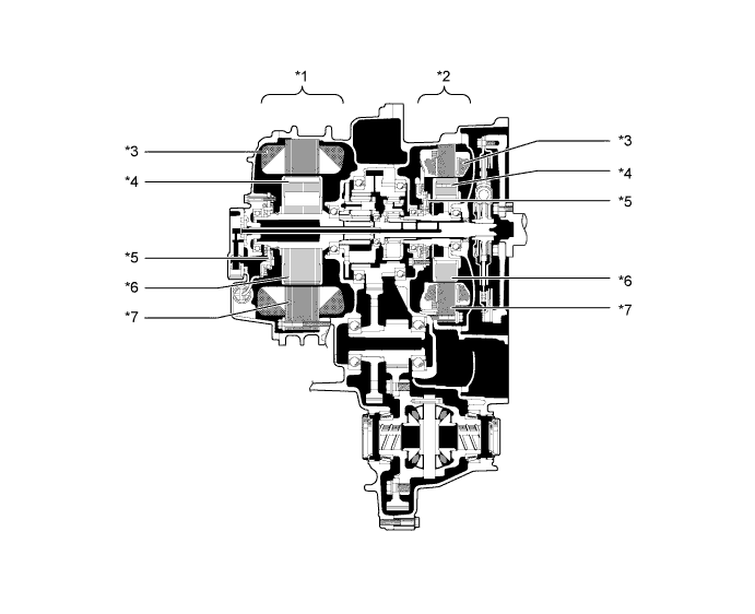
Text in Illustration *1 MG2 *2 MG1 *3 Stator Coil *4 Permanent Magnet *5 Resolver *6 Rotor *7 Stator - - -
When a three-phase alternating current is passed through the three-phase windings of the stator coil, a rotating magnetic field is created in the electric motor. By controlling this rotating magnetic field according to the rotor rotational position and speed, the permanent magnets that are provided in the rotor become attracted by the rotating magnetic field, thus generating torque.
-
The generated torque is for all practical purposes proportional to the amount of current, and the rotational speed is controlled by the frequency of the alternating current. Furthermore, a high level of torque, all the way to high speeds, can be generated efficiently by properly controlling the relationship of the rotating magnetic field to the angle of the rotor magnets.
-
When the motor is used to generate electricity, the rotation of the rotor creates a rotating magnetic field, which creates current in the phases of the stator coils.
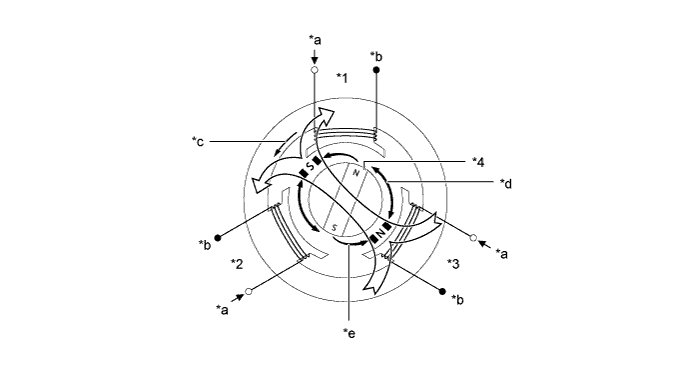
Text in Illustration *1 Stator Coil (U Phase) *2 Stator Coil (V Phase) *3 Stator Coil (W Phase) *4 Rotor (Permanent Magnet) *a from Inverter with Converter Assembly *b Connected Internally in the Motor *c Rotating Magnetic Field *d Repulsion *e Attraction - - 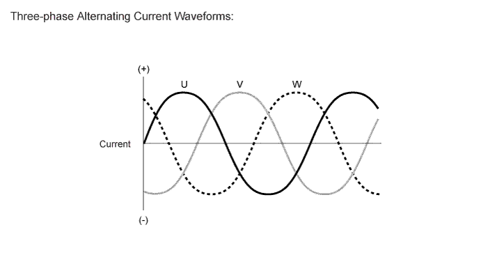
-
-
Resolver for MG1/MG2
-
A resolver is an extremely reliable and compact sensor that precisely detects the magnetic pole position. Knowing the precise position of the magnetic poles of the rotor (MG1 and MG2) is indispensable for ensuring efficient control of MG1 and MG2. MG1 and MG2 each have their own resolver.
-
The stator of the resolver contains 3 types of coils: excitation coil A, detection coil S and detection coil C.
-
The rotor of the resolver is oval, the distance of the gap between the stator and the rotor varies with the rotation of the rotor.
-
The flow of an alternating current into the excitation coil A results in the creation of a constant frequency magnetic field. Using this constant frequency magnetic field, the coil S and coil C will output values that correspond to the position of the rotor. Therefore, the MG ECU detects the absolute position based on the difference between the coil S and coil C output values.
-
The +S and -S pairs of the detection coil S are staggered by 90 degrees. The +C and -C pairs of the detection coil C are also staggered in the same way. The S and C pairs of coils are located 45 degrees from each other.
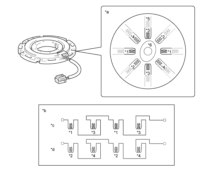
Text in Illustration *1 +S (Detection Coil S) *2 +C (Detection Coil C) *3 -S (Detection Coil S) *4 -C (Detection Coil C) *5 Excitation Coil A *6 Rotor *a Image of Resolver Internal Construction *b Electrical Orientation of Resolver Coils *c Circuit of Detection Coil S *d Circuit of Detection Coil C -
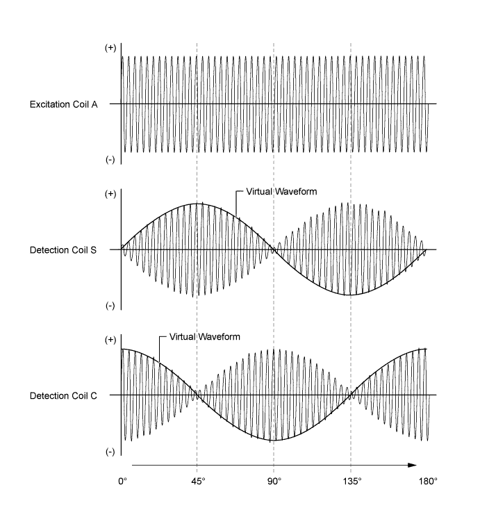
Because excitation coil A is provided with an alternating current at a constant frequency, a constant frequency magnetic field is output to the coils S and C, regardless of the rotor speed. The magnetic field of the excitation coil A is carried to the coils S and C by the rotor. The rotor is oval, and the gap between the stator and the rotor varies with the rotation of the rotor. Due to the variation of the gap, the peak values of the waveforms output by the coils S and C vary in accordance with the position of the rotor.
-
The MG ECU constantly monitors these peak values, and connects them to form a virtual waveform. The MG ECU calculates the absolute position of the rotor from the difference between the values of the coils S and C. It determines the rotor direction based on the difference between the phases of the virtual waveform of the coil S and the virtual waveform of the coil C. Furthermore, the MG ECU calculates the rotational speed based on the amount of change in the rotor position within a given length of time.
-
The diagrams below illustrate the waveforms that are output at coils A, S and C when the rotor makes a positive rotation of 180° from a certain position.
-
-
Temperature Sensor for MG1/MG2
-
The temperature sensors are used to detect the temperature of the MG1 and MG2 stators.
-
The power management control ECU optimally controls MG1 and MG2 according to the signals from each temperature sensor.
-
-
Inverter with Converter Assembly
-
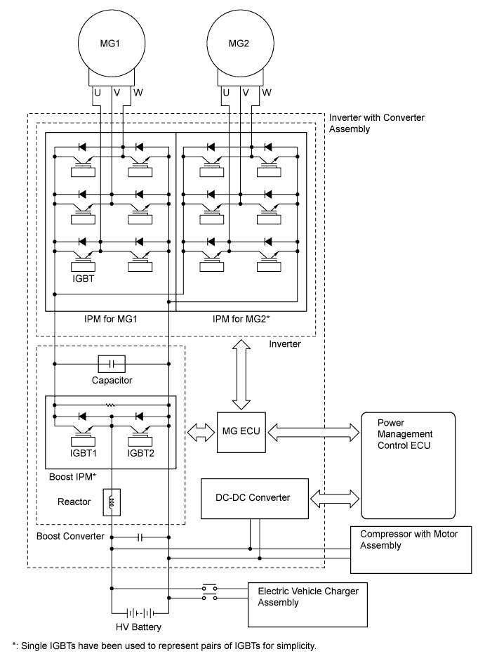
A compact, lightweight inverter with converter assembly, in which the MG ECU, inverter, boost converter, and DC-DC converter are integrated, is used. The inverter and boost converter primarily consist of Intelligent Power Modules (IPMs), a reactor, and capacitor. The IPM is an integrated power module consisting of a signal processor, protective function processor, and Insulated Gate Bipolar Transistors (IGBTs).
-
The inverter with converter assembly ensures heat dissipation through use of a water-cooled cooling system that is isolated from the engine cooling system.
-
As a safety measure due to the use of high-voltage electricity, interlock switches are provided, which shut off the system main relays via the power management control ECU when the inverter terminal cover is removed, or the HV battery power cable connector is disconnected.
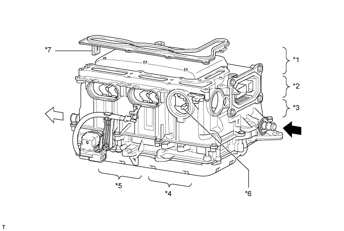
Text in Illustration *1 Capacitor *2 MG ECU *3 Intelligent Power Modules (IPMs) *4 Reactor *5 DC-DC Converter *6 Interlock Switch (for Power Cable Connector) *7 Interlock Switch (for Inverter Terminal Cover) - - 
HV Coolant Inlet 
HV Coolant Outlet -
The inverter employs an IPM that performs switching control. Each IPM of the MG1 and MG2 have a bridge circuit that consists of 6 IGBTs.
-
The boost converter consists of a boost IPM that performs switching control, a reactor that acts as an inductor, and a capacitor that accumulates and stores electricity. The boost IPM uses IGBT2 for boosting voltage, and IGBT1 for reducing voltage.
-
-
MG ECU
-
The MG ECU is provided in the inverter with converter assembly. In accordance with the signals received from the power management control ECU, the MG ECU controls the inverter and boost converter in order to drive MG1 or MG2 or cause them to generate electricity.
-
The MG ECU transmits information that is required for vehicle control, such as the atmospheric pressure, inverter temperature, amperage and any failure information, to the power management control ECU. It receives information that is required for controlling MG1 and MG2, such as the required motive force and the temperature of MG1 and MG2, from the power management control ECU.
-
-
Atmospheric Pressure Sensor
-
An atmospheric pressure sensor is provided on the MG ECU board.
-
This sensor detects the atmospheric pressure and transmits a signal to the MG ECU to allow corrections that correspond to the usage environment.
-
-
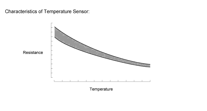
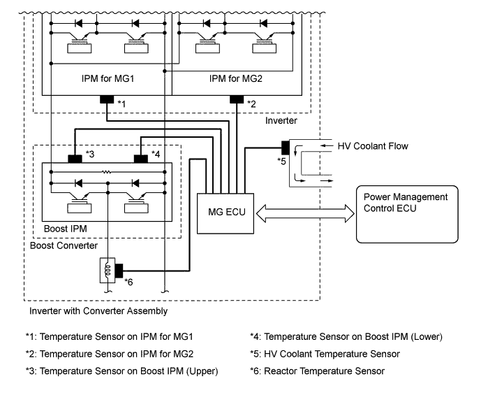
Temperature Sensor for Inverter with Converter Assembly
-
For the inverter with converter assembly, there are 5 different temperature sensors; 2 of them are located at the IPMs for MG1 and MG2, 2 of them are located at the boost converter, and the remaining sensor is located at the HV coolant passage.
-
These sensors detect the temperatures at areas inside the inverter with converter assembly, and transmit that temperature information to the power management control ECU via the MG ECU. The power management control ECU optimizes the cooling system according to the temperature information, maintaining the output performance of the inverter with converter assembly.
-
-
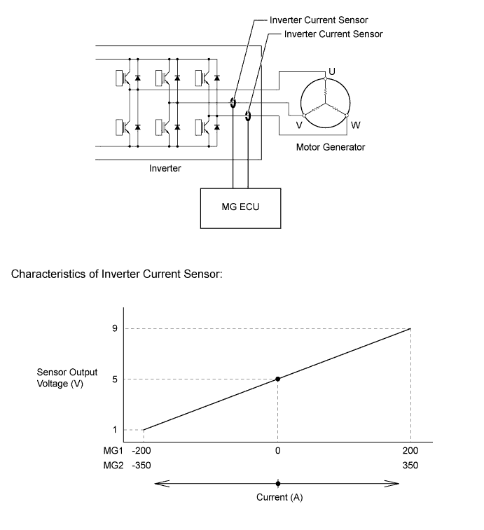
Inverter Current Sensors
-
The inverter current sensors detect the amperage of the three-phase alternating current that actuate MG1 and MG2. This actual amperage is used as feedback by the MG ECU.
-
Current sensors are used for the current sent to the three-phase windings of MG1 and MG2. They are located in the inverter with converter assembly for the V and W phases of each motor generator. Current that flows through the U phase winding flows through the V phase or W phase winding, thus the U phase amperage can be measured even if a current sensor is not set in the U phase winding.
-
-
HV Battery Assembly
-
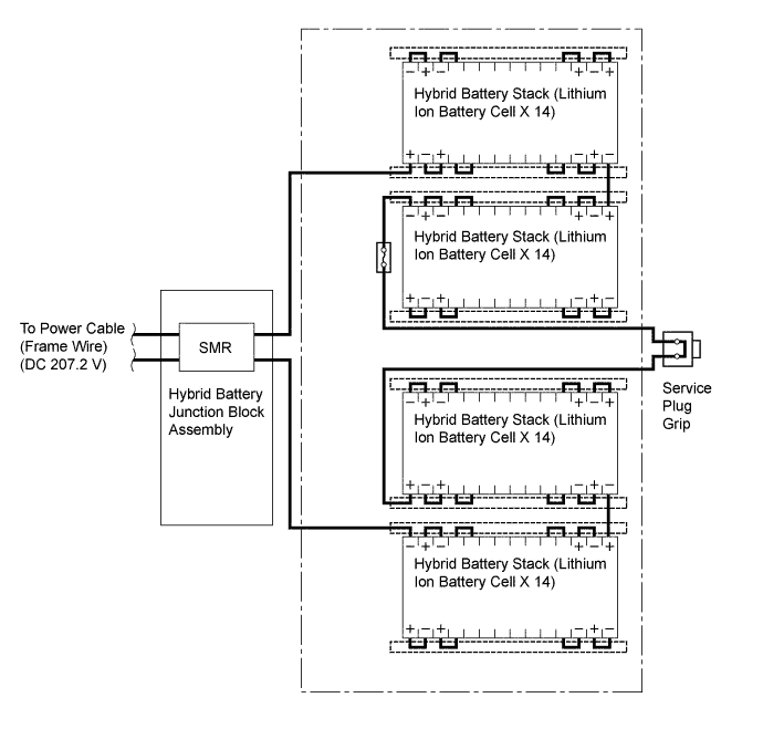
The HV battery assembly mainly consists of 4 hybrid battery stacks, a hybrid vehicle junction block assembly, 2 battery cooling blower assemblies, a battery smart unit, an aluminum frame and a service plug grip.
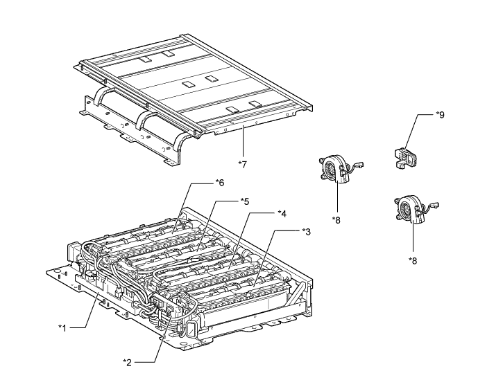
Text in Illustration *1 Hybrid Vehicle Junction Block Assembly *2 Battery Smart Unit *3 No. 1 Hybrid Battery Stack *4 No. 2 Hybrid Battery Stack *5 No. 3 Hybrid Battery Stack *6 No. 4 Hybrid Battery Stack *7 Aluminum Frame *8 Battery Cooling Blower *9 Service Plug Grip - - -
Compact, lightweight 3.7 V lithium-ion battery cells are used in order to generate high power output.
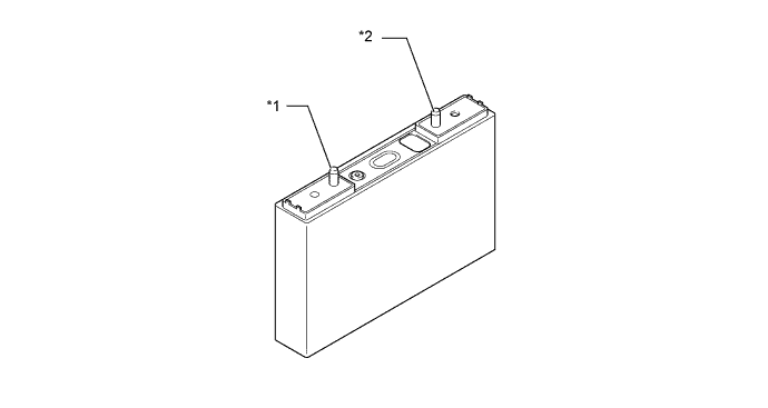
Text in Illustration *1 Positive Terminal *2 Negative Terminal -
The 14 lithium-ion battery cells provided for each hybrid battery stack are connected in series in a bus bar module, ensuring 51.8 V per stack.
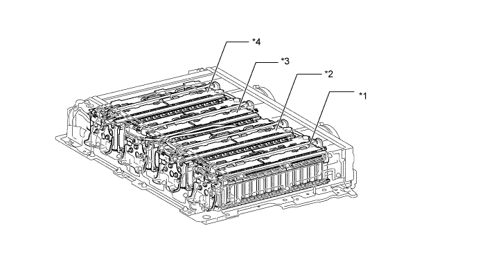
Text in Illustration *1 No. 1 Hybrid Battery Stack *2 No. 2 Hybrid Battery Stack *3 No. 3 Hybrid Battery Stack *4 No. 4 Hybrid Battery Stack -
The HV battery consists of 4 hybrid battery stacks. They are connected to each other in series through bus bar modules and wiring harness.
-
-
HV Battery Temperature Sensor and HV Battery Intake Air Temperature Sensor
-
12 thermistor type battery temperature sensors are provided in the HV battery to detect the temperature of the HV battery.
-
4 thermistor type intake air temperature sensor are provided to detect the temperature of the cooling air.
-
The power management control ECU optimally controls the cooling system so that the HV battery temperature and the cooling air temperature can be within a specified range according to the temperature information that is received via the battery smart unit.
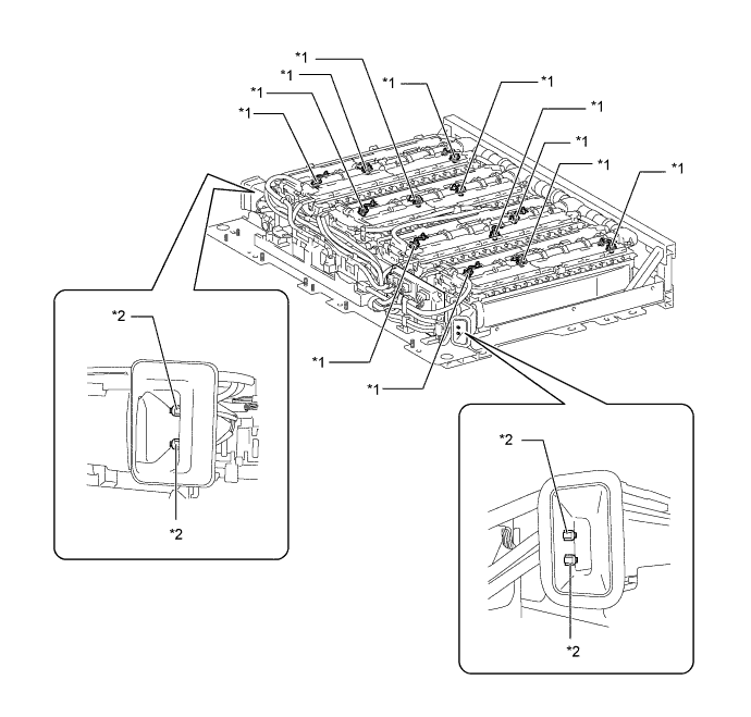
Text in Illustration *1 HV Battery Temperature Sensor *2 HV Battery Intake Air Temperature Sensor
-
-
Hybrid Battery Junction Block Assembly
-
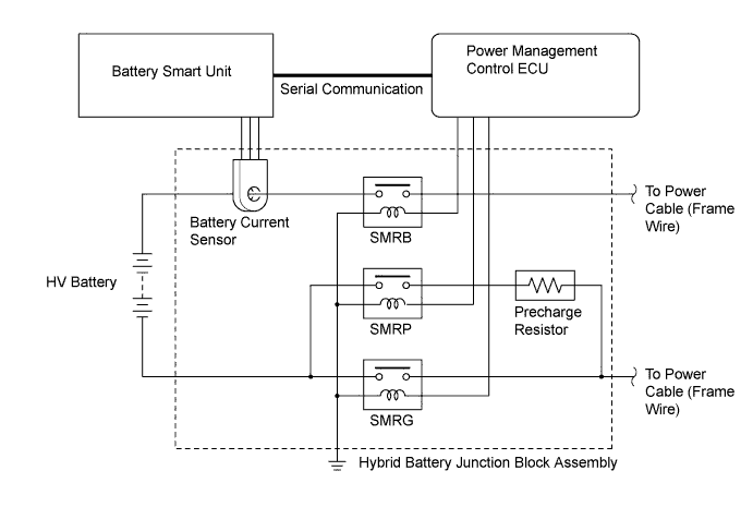
The hybrid battery junction block assembly consists of the System Main Relays (SMRs), precharge resistor and battery current sensor.
-
The SMRs are relays that connect and disconnect the HV battery and power cable (frame wire) in accordance with the signal from the power management control ECU. 3 relays are provided; SMRB for the battery positive (+) side, SMRG for the battery negative (-) side, and SMRP for pre-charging.
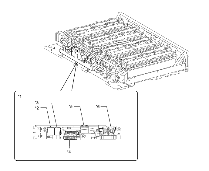
Text in Illustration *1 Hybrid Vehicle Junction Block Assembly *2 Charging Relay (CHRG) *3 Charging Relay (CHRB) *4 SMRB *5 SMRP *6 SMRG
-
-
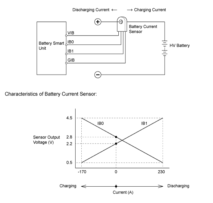
Battery Current Sensor
-
A battery current sensor, which is built into the hybrid vehicle junction block assembly, is used to detect the hybrid battery stack charging and discharging amperage.
-
The power management control ECU optimally controls the hybrid system so that the SOC of the hybrid battery stack can always be within a specified range according to the amperage information that is received via the battery smart unit.
-
-
Battery Smart Unit
-
The battery smart unit monitors the conditions of the hybrid battery stacks such as voltage, current and temperature, and transmits this information to the power management control ECU.
-
Also, the battery smart unit detects and transmits the blower speed feedback voltage, which is necessary to perform cooling system (for HV battery) control, to the power management control ECU.
-
A leakage detection circuit is provided in the battery smart unit in order to detect electrical leakage from the hybrid battery stacks or high-voltage circuit.
-
The battery smart unit converts these signals into digital signals and transmits them to the power management control ECU via serial communication.
-
When the power switch is turned off, the battery smart unit equalizes the voltage of each battery cell in the HV battery to use the HV battery output effectively.
-
-
Service Plug Grip
-
The service plug grip is connected in the middle of the hybrid battery stack circuit and is used for manually shutting off the high-voltage circuit. This ensures safety during service.
-
An interlock switch is provided on the service plug grip. When the grip section is unlocked, the interlock switch is turned off and the power management control ECU shuts off the SMR. However, to ensure safety, make sure to turn the power switch off before removing the service plug grip.
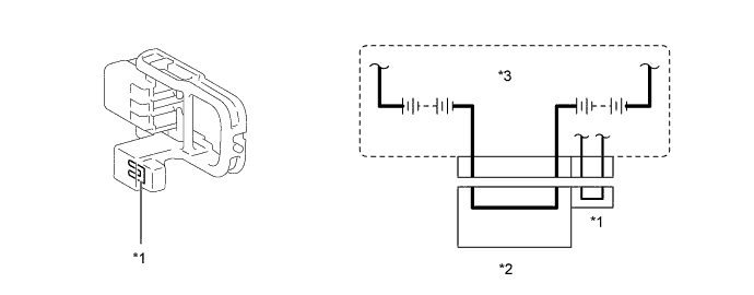
Text in Illustration *1 Interlock Switch *2 Service Plug Grip *3 HV Battery - - CAUTION:
For further details on how to handle the service plug grip and other safety cautions, refer to the Repair Manual.
-
-
Power Cable (Frame Wire)
-
The power cable (frame wire) is a set of high-voltage, high-amperage cables that connect the HV battery assembly with the inverter with converter assembly, the HV battery assembly with electric vehicle charger assembly, the inverter with converter assembly with MG1 and MG2, and the inverter with converter assembly with the compressor with motor assembly.
-
The power cable (frame wire) is made of shielded cables in order to reduce electromagnetic interference.
-
For identification purposes, the high-voltage wiring harness and connectors are color-coded orange to distinguish them from those of the ordinary low-voltage wiring.
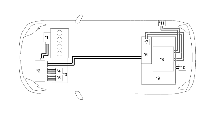
Text in Illustration *1 Compressor with Motor Assembly *2 Inverter with Converter Assembly *3 Hybrid Vehicle Transaxle Assembly *4 MG1 *5 MG2 *6 Hybrid Battery Junction Block Assembly *7 Charging Relay *8 Electric Vehicle Charger Assembly *9 HV battery *10 Service Plug Grip *11 Charging Inlet (Electric Vehicle Charger Cable) - - 
Power Cable (Frame Wire) 
Electric Vehicle Charger Cable Wire
-
-
Inverter Water Pump Assembly
-
A compact and highly efficient electric type inverter water pump assembly is used.
-
A high output brushless type motor is used for the pump motor, furthermore, bearings that support the shaft at both ends are employed, thus suppressing noise and vibration.
-
The pump motor is controlled over 3 levels by the duty cycle signal from the power management control ECU.
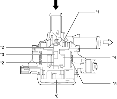
Text in Illustration *1 Impeller *2 Bearing *3 Shaft *4 Rotor *5 Stator *6 Motor Controller HV Coolant Inlet HV Coolant Outlet
-
-
Battery Cooling Blower Assembly
-
A compact and highly efficient battery cooling blower assembly is used.
-
A high output brushless type motor is used for the blower motor, and the inner shape of the blower case has been optimized. As a result, blower noise is reduced.
-
The blower motor has a built-in motor controller, and is controlled in a variable manner by the duty cycle signal from the power management control ECU.
-
-
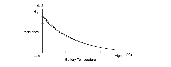
Auxiliary Battery Temperature Sensor (Thermistor Assembly)
-
The auxiliary battery temperature sensor (thermistor assembly) detects the auxiliary battery temperature, and transmits temperature signals to the power management control ECU.
-
Based on the signal from the sensor, in order to maintain the optimal charging state appropriate to the auxiliary battery temperature, the power management control ECU regulates the output voltage from the DC-DC converter.
-
-
Accelerator Pedal Sensor Assembly
-
This non-contact type accelerator pedal sensor assembly uses a Hall IC.
-
A magnetic yoke is mounted at the base of the accelerator pedal arm. This yoke rotates around the Hall IC in accordance with the amount of effort that is applied to the accelerator pedal. The Hall IC converts the changes in the magnetic flux that occur into electrical signals, and outputs accelerator pedal position signals to the power management control ECU.
-
The Hall IC contains 2 circuits, one for the main signal, and one for the sub signal. It converts the accelerator pedal position (angle) into electric signals that have differing characteristics and outputs them to the power management control ECU.
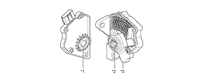
Text in Illustration *1 Hall IC *2 Magnetic Yoke *3 Accelerator Pedal Arm - - 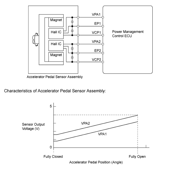
-
-
-
OPERATION
-
Operation of Plug-in Hybrid Vehicle
-
The plug-in hybrid system uses motive force provided by the engine and MG2, and it uses MG1 as a generator. The system optimally combines these forces in accordance with various driving conditions.
-
The power management control ECU constantly monitors the engine coolant temperature, SOC, HV battery temperature and electrical load conditions. If any of the monitoring conditions fails to satisfy the requirements, and when the vehicle is in the READY-on state and the shift position is any position other than N, the power management control ECU starts the engine.
-
This system drives the vehicle by optimally combining the operations of the engine, MG1 and MG2 in accordance with the driving conditions listed below. The vehicle conditions listed below are examples of typical vehicle driving conditions.
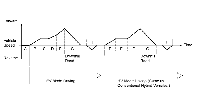
Driving Condition A READY-on State B Starting Off C Constant-speed Cruising in EV Mode D Normal Acceleration in EV Mode E Constant-speed Cruising in HV Mode F During Full Throttle Acceleration with Engine Running G During Deceleration H During Reverse
-
-
How to Read a Nomographic Chart
-
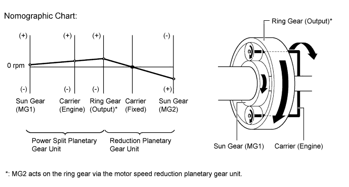
The nomographic chart below gives a visual representation of the planetary gear rotation direction, rotational speed and torque balance.
-
In the nomographic chart, a straight line is used to represent the relationship between the rotation directions and rotational speeds of the 3 gears in the planetary gear. The rotational speed of each gear is indicated by the distance from the 0 rpm point. Due to the structure of the planetary gear, the relationship between the rotational speeds of the 3 gears is always expressed by a straight line.
-
The nomographic charts and the illustrations of the geartrain operation for each vehicle driving condition shown on the following descriptions are examples only. The examples shown are 'snapshots', normal system operation is a constantly changing blend of conditions and system reactions to suit those conditions.
-
For the hybrid system, motor generators have different roles depending on the situation. Understanding the relationship between the rotation direction and torque can help to make the role of a motor generator easier to understand.
-
The table below shows the relationship of drive and electric generation for different combinations of plus or negative torque and forward or reverse rotation.
Rotation Direction Torque Condition Role of Component Forward (+) Rotation Positive Torque Drive Negative Torque Electric Generation Reverse (-) Rotation Positive Torque Electric Generation Negative Torque Drive -
As an example, if a motor generator is rotating in the forward (+) direction and it applies negative torque, it will generate electricity (producing electrical power).
-
Alternately, if the motor generator is rotating in the reverse (-) direction and it applies negative torque, it will act as a drive source (consuming electrical power).
-
-
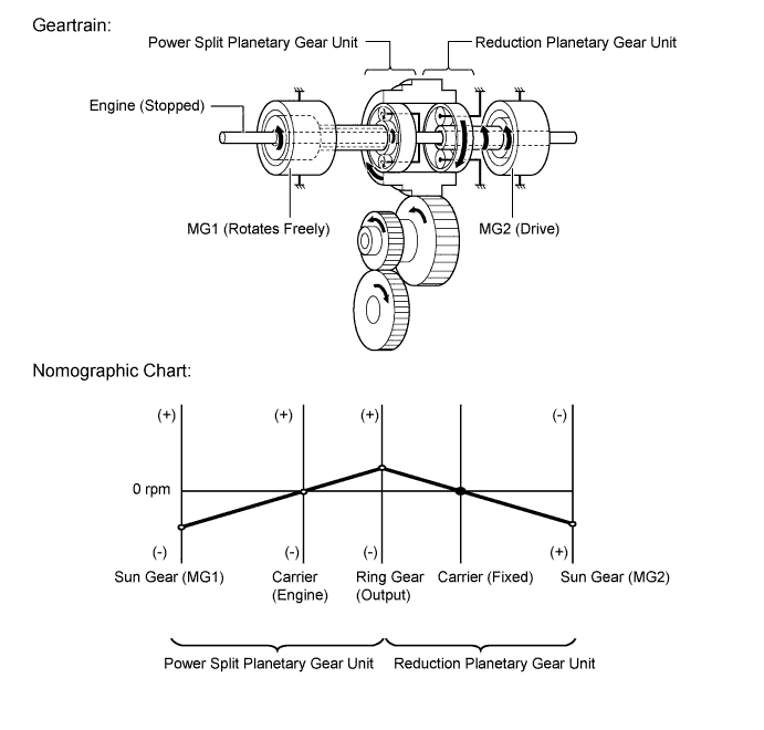
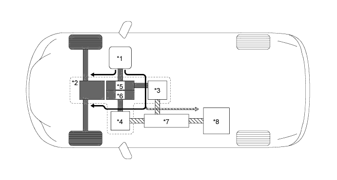
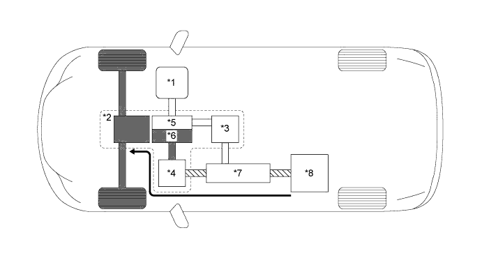
Driving Condition B*: Starting Off
-
When the vehicle is started off, the vehicle operates powered by MG2. If the required drive torque increases when running with MG2 only, MG1 is activated to start the engine.
Tech Tips
*: Refer to the preceding driving condition graph and table for more details.

Text in Illustration *1 Engine (Stopped) *2 Hybrid Vehicle Transaxle Assembly *3 MG1 (Rotates Freely) *4 MG2 (Drive) *5 Power Split Planetary Gear Unit *6 Motor Speed Reduction Planetary Gear Unit *7 Inverter with Converter Assembly *8 HV Battery 
Mechanical Power Path 
Electrical Power Path Power Transmission - - -
While the vehicle is running with the motive force of MG2 only, the rotational speed of the carrier (engine) is 0 rpm due to the engine being stopped. In addition, since MG1 does not generate any torque, no torque acts on the sun gear (MG1). However, the sun gear rotates freely in the (-) direction balancing the rotating ring gear.
-
-
Driving Condition C*: Constant-speed Cruising in EV Mode / Driving Condition D*: Normal Acceleration in EV Mode
-
During constant-speed cruising in EV mode (Driving Condition C) and normal acceleration in EV mode (Driving Condition D), the vehicle runs with only the motive force of MG2, powered by the plug-in charged HV battery.
Tech Tips
*: Refer to the preceding driving condition graph and table for more details.

Text in Illustration *1 Engine (Stopped) *2 Hybrid Vehicle Transaxle Assembly *3 MG1 (Rotates Freely) *4 MG2 (Drive) *5 Power Split Planetary Gear Unit *6 Motor Speed Reduction Planetary Gear Unit *7 Inverter with Converter Assembly *8 HV Battery Mechanical Power Path Electrical Power Path Power Transmission - - -
The geartrain and nomographic chart for the above conditions are the same as driving condition B (starting off).
-
-
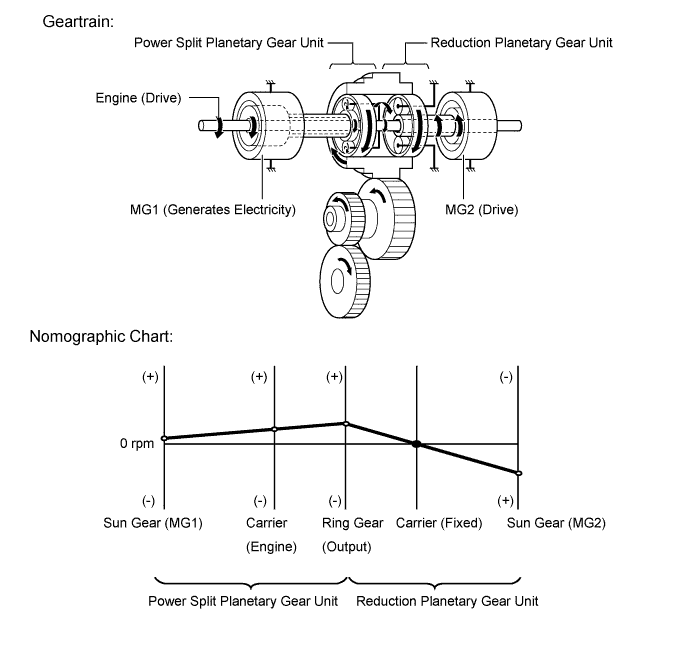
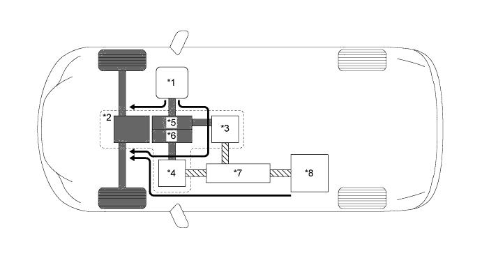
Driving Condition E*: Constant-speed Cruising in HV Mode
-
When driving at high speed or with constant-speed cruising after EV mode driving finishes, the motive force of the engine is transmitted by the power split planetary gear unit. Some of this motive force is output directly, and the remaining motive force is used for generating electricity through MG1. Through the use of the electrical power path of the inverter with converter assembly, this electrical power is transmitted to MG2 to be output as the motive force of MG2. If the SOC level of the HV battery is low, it is charged by MG1 driven by the engine.
Tech Tips
*: Refer to the preceding driving condition graph and table for more details.
Text in Illustration *1 Engine (Drive) *2 Hybrid Vehicle Transaxle Assembly *3 MG1 (Generates Electricity) *4 MG2 (Drive) *5 Power Split Planetary Gear Unit *6 Motor Speed Reduction Planetary Gear Unit *7 Inverter with Converter Assembly *8 HV Battery Mechanical Power Path Electrical Power Path Power Transmission 
Power Transmission at Low SOC Level -
The torque from the engine acts on the carrier (engine) in the (+) direction, causing the sun gear (MG1) to turn in the (+) direction due to the reaction of negative torque. MG1 generates electricity by harnessing the negative torque that acts on the sun gear (MG1).
-
-
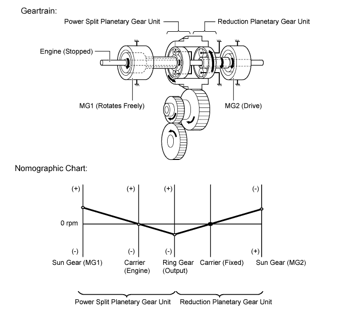
Driving Condition F*: During Full Throttle Acceleration with Engine Running
-
During EV mode, full throttle acceleration will cause the engine to start. The engine power will be transmitted to the wheels as motive force. Furthermore, MG1 will also be actuated to generate electrical power. In addition to the engine, the motive force of MG2, powered by the HV battery and MG1, accelerates the vehicle.
-
When the vehicle driving condition changes from low load cruising to full-throttle acceleration, the system supplements the motive force of MG2 with electrical power from the HV battery.
Tech Tips
*: Refer to the preceding driving condition graph and table for more details.
Text in Illustration *1 Engine (Drive) *2 Hybrid Vehicle Transaxle Assembly *3 MG1 (Generates Electricity) *4 MG2 (Drive) *5 Power Split Planetary Gear Unit *6 Motor Speed Reduction Planetary Gear Unit *7 Inverter with Converter Assembly *8 HV Battery Mechanical Power Path Electrical Power Path Power Transmission - - -
When more engine power is required, in order to increase the engine speed, the rotational speeds of the related gears change as follows. The torque from the engine acts on the carrier (engine) in the (+) direction, causing the sun gear (MG1) to react with negative torque. MG1 generates electricity by harnessing the negative torque that acts on the sun gear (MG1).

-
-
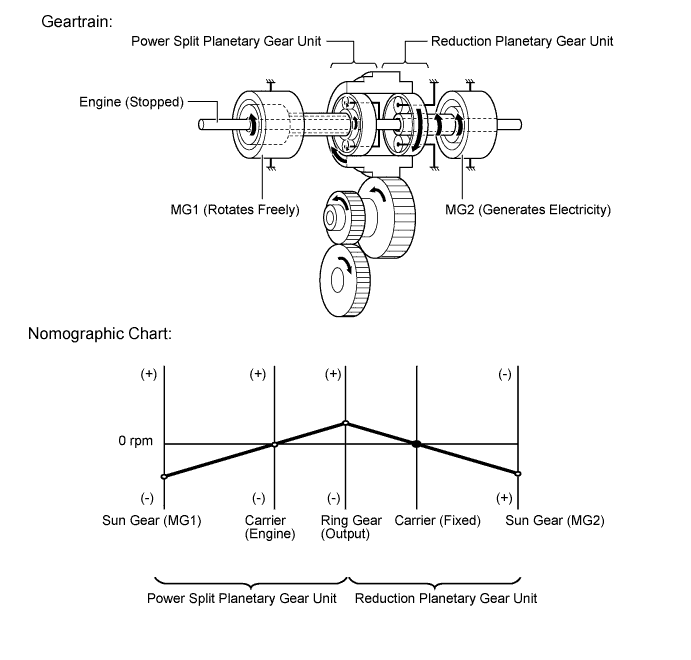
Driving Condition G*: During Deceleration
-
While the vehicle decelerates with drive (D) selected, the engine is turned off and the motive force changes to zero. At this time, the wheels drive MG2, causing MG2 to operate as a generator, charging the HV battery. If the vehicle decelerates from a higher speed, the engine maintains a predetermined speed without stopping, in order to protect the planetary gears.
Tech Tips
*: Refer to the preceding driving condition graph and table for more details.

Text in Illustration *1 Engine (Stopped) *2 Hybrid Vehicle Transaxle Assembly *3 MG1 (Rotates Freely) *4 MG2 (Generates Electricity) *5 Power Split Planetary Gear Unit *6 Motor Speed Reduction Planetary Gear Unit *7 Inverter with Converter Assembly *8 HV Battery Mechanical Power Path Electrical Power Path Power Transmission - - -
During deceleration, the ring gear is rotated by the wheels. Under this condition, due to the engine being stopped, the rotational speed of the carrier (engine) is 0 rpm. In addition, since MG1 does not generate any torque, no torque acts on the sun gear (MG1). However, the sun gear (MG1) rotates freely in the (-) direction, balancing the rotating ring gear.
-
-
Driving Condition H*: During Reverse
-
When the vehicle is being driven in reverse, the required power is supplied by MG2. At this time, MG2 rotates in the opposite direction, the engine remains stopped, and MG1 rotates in the normal direction without generating electricity.
Tech Tips
*: Refer to the preceding driving condition graph and table for more details.
Text in Illustration *1 Engine (Stopped) *2 Hybrid Vehicle Transaxle Assembly *3 MG1 (Rotates Freely) *4 MG2 (Drive) *5 Power Split Planetary Gear Unit *6 Motor Speed Reduction Planetary Gear Unit *7 Inverter with Converter Assembly *8 HV Battery Mechanical Power Path Electrical Power Path Power Transmission - - -
The conditions of the planetary gear are opposite to those described in "Starting Off". Due to the engine being stopped, the rotational speed of the carrier (engine) is 0 rpm but the sun gear (MG1) rotates freely in the (+) direction, balancing the rotating ring gear.
-
-
-
DIAGNOSIS
-
When the power management control ECU detects a malfunction in the hybrid system, the power management control ECU performs a diagnosis and memorizes the failed section. To inform the driver of the malfunction, the power management control ECU illuminates or blinks the Malfunction Indicator Lamp (MIL) or master warning light and displays a message in the multi-information display. At the same time, the Diagnostic Trouble Code (DTC) is stored in its memory.
-
3-digit information codes (INF codes) have been provided with the conventional DTC as subset of the primary 5-digit code. This enables the troubleshooting procedure to further narrow down a trouble area to identify a problem.
-
The DTC can be read by connecting the Global TechStream (GTS) to the DLC3. For details, refer to the Repair Manual.
-